Sensor housing for a radar sensor and radar sensor
US20180359875A1
2018-12-13
15/566,293
2016-05-03
✅ Patent granted
US 10,375,848 B2
2019-08-06
WO; PCT/EP2016/059862; 20160503
WO; WO2016/184679; 20161124
William H. Mayo, III | Hiram E Gonzalez
Husch Blackwell LLP
2036-05-03
Abstract:
A sensor housing for a radar sensor for a vehicle comprising a housing and a printed circuit board. The housing has a venting duct for the venting of the sensor housing, as well as a press-fit guide for the reception of a positioning aid for the printed circuit board. The venting duct and the press-fit guide form a common duct.
Assignee:
- HELLA GmbH Co. KGaA 583 🇩🇪 Lippstadt, Germany
Applicant:
Interested in similar patents?
Get notified when new applications in this technology area are published.
Classification:
H05K7/1427 » CPC main
Constructional details common to different types of electric apparatus; Mounting supporting structure in casing or on frame or rack; Printed circuit boards receptacles, e.g. stacked structures, electronic circuit modules or box like frames Housings
H05K7/1427 » CPC main
Constructional details common to different types of electric apparatus; Mounting supporting structure in casing or on frame or rack; Printed circuit boards receptacles, e.g. stacked structures, electronic circuit modules or box like frames Housings
G01S13/931 » CPC further
Systems using the reflection or reradiation of radio waves, e.g. radar systems; Analogous systems using reflection or reradiation of waves whose nature or wavelength is irrelevant or unspecified; Radar or analogous systems specially adapted for specific applications for anti-collision purposes of land vehicles
H01R12/585 » CPC further
Structural associations of a plurality of mutually-insulated electrical connecting elements, specially adapted for printed circuits, e.g. printed circuit boards [PCBs], flat or ribbon cables, or like generally planar structures, e.g. terminal strips, terminal blocks; Coupling devices specially adapted for printed circuits, flat or ribbon cables, or like generally planar structures; Terminals specially adapted for contact with, or insertion into, printed circuits, flat or ribbon cables, or like generally planar structures; Fixed connections for rigid printed circuits or like structures characterised by the terminals terminals for insertion into holes Terminals having a press fit or a compliant portion and a shank passing through a hole in the printed circuit board
H05K5/0039 » CPC further
Casings, cabinets or drawers for electric apparatus provided with connectors and printed circuit boards [PCB], e.g. automotive electronic control units having a tubular housing wherein the PCB is inserted longitudinally
H05K5/0039 » CPC further
Casings, cabinets or drawers for electric apparatus provided with connectors and printed circuit boards [PCB], e.g. automotive electronic control units having a tubular housing wherein the PCB is inserted longitudinally
H05K5/0213 » CPC further
Casings, cabinets or drawers for electric apparatus; Details Venting apertures; Constructional details thereof
H05K5/0213 » CPC further
Casings, cabinets or drawers for electric apparatus; Details Venting apertures; Constructional details thereof
H05K7/1418 » CPC further
Constructional details common to different types of electric apparatus; Mounting supporting structure in casing or on frame or rack having securing means for mounting boards, plates or wiring boards Card guides, e.g. grooves
H05K7/1418 » CPC further
Constructional details common to different types of electric apparatus; Mounting supporting structure in casing or on frame or rack having securing means for mounting boards, plates or wiring boards Card guides, e.g. grooves
H05K5/02 IPC
Casings, cabinets or drawers for electric apparatus Details
H05K5/02 IPC
Casings, cabinets or drawers for electric apparatus Details
H05K5/00 IPC
Casings, cabinets or drawers for electric apparatus
H05K5/00 IPC
Casings, cabinets or drawers for electric apparatus
G01S13/93 IPC
Systems using the reflection or reradiation of radio waves, e.g. radar systems; Analogous systems using reflection or reradiation of waves whose nature or wavelength is irrelevant or unspecified; Radar or analogous systems specially adapted for specific applications for anti-collision purposes
G01S7/03 » CPC further
Details of systems according to groups of systems according to group Details of HF subsystems specially adapted therefor, e.g. common to transmitter and receiver
H05K7/14 IPC
Constructional details common to different types of electric apparatus Mounting supporting structure in casing or on frame or rack
H05K7/14 IPC
Constructional details common to different types of electric apparatus Mounting supporting structure in casing or on frame or rack
H01R13/66 IPC
Details of coupling devices of the kinds covered by groups or - Structural association with built-in electrical component
H01R13/6658 » CPC further
Details of coupling devices of the kinds covered by groups or -; Structural association with built-in electrical component with built-in electronic circuit on printed circuit board
H01R13/6683 » CPC further
Details of coupling devices of the kinds covered by groups or -; Structural association with built-in electrical component with built-in electronic circuit with built-in sensor
H01R13/74 IPC
Details of coupling devices of the kinds covered by groups or -; Means for mounting coupling parts to apparatus or structures, e.g. to a wall Means for mounting coupling parts in openings of a panel
H05K5/0069 » CPC further
Casings, cabinets or drawers for electric apparatus provided with connectors and printed circuit boards [PCB], e.g. automotive electronic control units having connector relating features for connecting the connector pins with the PCB or for mounting the connector body with the housing
G01S7/02 » CPC further
Details of systems according to groups of systems according to group
H01R13/748 » CPC further
Details of coupling devices of the kinds covered by groups or -; Means for mounting coupling parts to apparatus or structures, e.g. to a wall; Means for mounting coupling parts in openings of a panel using one or more screws
H01R2201/26 » CPC further
Connectors or connections adapted for particular applications for vehicles
H01R12/58 » CPC further
Structural associations of a plurality of mutually-insulated electrical connecting elements, specially adapted for printed circuits, e.g. printed circuit boards [PCBs], flat or ribbon cables, or like generally planar structures, e.g. terminal strips, terminal blocks; Coupling devices specially adapted for printed circuits, flat or ribbon cables, or like generally planar structures; Terminals specially adapted for contact with, or insertion into, printed circuits, flat or ribbon cables, or like generally planar structures; Fixed connections for rigid printed circuits or like structures characterised by the terminals terminals for insertion into holes
Description
CROSS REFERENCE
This application claims priority to PCT Patent Application No. PCT/EP2016/059862, filed 3 May 2016, which itself claims priority to German Application No. 10 2015 107645.4, filed 15 May 2015, the entirety of both of which are hereby incorporated by reference.
FIELD OF THE INVENTION
The invention relates to a sensor housing for a radar sensor for a vehicle. Furthermore, the invention relates to a radar sensor with the sensor housing.
BACKGROUND OF THE INVENTION
The sensor housings for vehicle radar sensors known from the prior art have a connector and a printed circuit board. Herein, the connector has a venting duct for the venting of the sensor housing on one hand and a press-fit guide for the reception of a positioning aid for the printed circuit board.
The disadvantage of the prior art is that a multitude of manufacturing steps is required for the production of a sensor housing until the sensor housing can be used.
SUMMARY OF THE INVENTION
It is, therefore, the task of the present invention to provide a connector which can be mounted in a space-saving manner and which can be produced in a simple and inexpensive manner.
According to the invention, the task is solved in particular by means of a sensor housing for a radar sensor for a vehicle comprising a connector and a printed circuit board, wherein the connector has a venting duct for the venting of the sensor housing and a press-fit guide for the reception of a positioning aid for the printed circuit board, wherein the venting duct and the press-fit guide form a common duct.
Furthermore, the task is solved according to the invention in particular by a radar sensor for a vehicle comprising a sensor housing.
The particular advantage of the invention is that by combining the venting duct and the press-fit guide, the space requirements for a possible sealing area and for the placement of electronic components are minimized.
Advantageously, a positioning structure such as one or more press-fit pins can be led through openings in the printed circuit board. Particularly advantageously the positioning structures engage in respective recesses arranged in the connector. Advantageously the positioning structures are introduced as soon as the printed circuit board is positioned by means of the positioning structures.
Preferably a component holder is placed between the connector and the printed circuit board. Preferably the printed circuit board can be fastened on the component holder by means of the positioning structures.
Preferentially the venting duct serves venting. Preferably a common duct is a continuous duct combining the venting duct and the press-fit guide.
Preferentially the printed circuit board (PCB) is a carrier for electronic components. It serves the mechanical fastening and the electrical connection.
Preferably printed circuit boards are made from an electrically insulating material with adhering conductive connections (PCB tracks). Preferably, fiber-reinforced plastic material is common as an insulating material. The PCB tracks are preferably etched from a thin copper layer. The components can be soldered on solder pads or solder lands. By this means they are at the same time mechanically held and electrically connected on these footprints. Preferably larger components are also fastened on the printed circuit board with cable ties, adhesive or by means of screw-fastening.
According to a further development of the invention, the duct ends with one of his ends in a connector housing of the sensor housing. The venting of the sensor housing can be achieved by this means.
According to a further development of the invention, the connector with the duct is embodied as an injection-molded part. By providing an injection-molded part, the connector with the continuous duct can be produced in a simple manner.
According to a further development of the invention, the duct is embodied as a drill hole in the connector. By this means, the duct can be introduced into the connector in a simple manner. Preferably, the drill hole is introduced into the connector by means of a drilling process.
According to a further development of the invention, the duct is embodied in a tube-shaped manner. Preferably, the tube-shaped duct has a variable diameter. According to a further development of the invention, the duct has a bend. By providing the bend, the press-fit guide and the venting duct can be connected in a simple manner.
According to a further development of the invention, the press-fit guide is oriented in an approximately vertical manner relative to the venting duct in the sensor housing. Preferably, the venting duct is inclined relative to the press-fit guide by an angle of 85° to 95°. Particularly preferably, the venting duct is inclined by 90° relative to the press-fit guide.
Preferentially, the radar sensor is embodied as a lane change assistant on the basis of a 24 GHz-radar sensor system. Preferably it is equipped to observe the rear permanently and warns the driver during take-over or lane change processes of vehicles approaching from the rear on the neighboring lane. Lane changes result in an increased risk of accidents, particularly due to the so-called blind spot. The lane change assistant observes this “blind spot” and warns the driver of risky lane changes. Preferably, the sensors of the lane change assistant are equipped to detect for example fast-driving motorcyclists to prevent accidents.
Preferably, the radar sensor is embodied as a “vehicle interval warning system” on the basis of a 24-GHz-radar sensor system which warns the driver when the allowed safety distance is exceeded, but does not intervene autonomously in the drive train. Preferentially, the radar sensor is embodied as a 3-function-camera comprising lane and traffic sign recognition as well as an adaptive/dazzle-free high beam function. In the lane keep assistant function, the vehicle is moved back to the middle of the lane as soon as the driver comes too close to the lane marking.
BRIEF DESCRIPTION OF THE DRAWINGS
Reference is now made more particularly to the drawings, which illustrate the best presently known mode of carrying out the invention and wherein similar reference characters indicate the same parts throughout the views.
FIG. 1a is a schematic view of a connector for a radar sensor.
FIG. 1b is a further schematic view of the connector of FIG. 1a.
FIG. 2a is a schematic section through a first partial area of a sensor housing with the connector of FIG. 1a.
FIG. 2b is a schematic section through a second partial area of the sensor housing with the connector of FIG. 1a.
FIG. 3 is a schematic section through a part of a sensor housing for a radar sensor according to the invention.
FIG. 4 is a further schematic section through a partial area of the sensor housing of FIG. 3 in a simplified representation.
DETAILED DESCRIPTION OF THE DRAWINGS
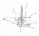
FIG. 1a shows a schematic view of a connector for a radar sensor and FIG. 1b shows a further schematic view of the connector of FIG. 1a.
The connector 2 has a connector housing 5. The connector 2 is suitable for the reception of a mating connector (not represented) fitting the connector housing. Furthermore, four drill holes 13 are provided in the connector 2 to allow the fastening of the connector 2. Furthermore, the connector 2 has a contact connection 14 to be connected with a radar sensor (not represented).
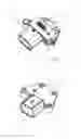
FIG. 2a shows a schematic section through a first partial area of a sensor housing with the connector of FIG. 1a.
The sensor housing 20 comprises the connector 2, a component carrier 3 and a printed circuit board 4. The component carrier 3 is arranged between the connector 2 and the printed circuit board 4. The connector 2 has a press-fit guide 10 for the reception of a positioning aid 15, a metal spike, for the printed circuit board 4. To preposition the printed circuit board 4 for a pressing-in of press-in pins (not represented), the printed circuit board 4 is penetrated by the positioning aid 15. Herein, the positioning aid 15 is guided through an opening 6 in the printed circuit board 4 until the one end of the positioning aid 15 has contact with a cylinder 7 arranged on the bottom of the connector 2. On The positioning aid 15 is inserted in the drawing plane from above in a vertical direction into the sensor housing 20. This ensures that the tolerance of the printed circuit board 4 to the connector 2 is as small as possible.
FIG. 2b is a schematic section through a second partial area of the sensor housing with the connector of FIG. 1a.
The sensor housing 20 comprises the connector 2, a component carrier 3 and a printed circuit board. The component carrier 4 is arranged between the connector 2 and the printed circuit board 4. Furthermore, the connector housing 5 for the reception of the mating connector part (not represented) is provided. The connector 2 has a venting duct 9 for the venting of the sensor housing 20. This ensures an easy venting of the sensor housing 20.
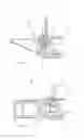
FIG. 3 is a schematic section through a partial area of a sensor housing according to the invention for a radar sensor and FIG. 4 is a further schematic section through a partial area of the sensor housing of FIG. 3 in a simplified representation.
The sensor housing 1 has a connector 2, a component carrier 3, and a printed circuit board 4. The component carrier 3 is arranged between the connector 2 and the printed circuit board 4. The connector 2 has a duct 11. The duct 11 unites a venting duct 9 and a press-fit guide 10.
Herein, the press-fit guide 10 serves the reception of a positioning aid 15 for the printed circuit board 4. To preposition the printed circuit board 4 for the pressing-in of press-in pins (not represented), the printed circuit board 4 is penetrated by the positioning aid 15. Herein, the positioning aid 15 is guided through an opening 6 in the printed circuit board 4 until the one end of the metal spike has contact with the venting duct. The positioning aid 15 is inserted in the drawing plane from above in a vertical direction into the sensor housing 1. This ensures that the tolerance of the printed circuit board 4 to the connector 2 is as small as possible.
The venting duct 9 is provided for the venting of the sensor housing 1 to ensure an easy venting of the sensor housing 20. At one of its ends, the duct 11 ends in the connector housing 5 of the sensor housing 1. The duct 11 is embodied in a tube-shaped manner and has a bend. Herein, the press-fit guide 10 is arranged in an approximately vertical manner relative to the venting duct 9 in the sensor housing 1.
By providing the common duct, the combination of venting duct and press-fit guide can minimize the space requirements for a possible sealing area and for the placement of electronic components.
The above description of the embodiments describes the present invention solely on the basis of examples. If technically sensible, the individual characteristics of the embodiments can, of course, be feely combined without leaving the basis of the present invention.
LIST OF REFERENCE SIGNS
1 Sensor housing
2 Connector
3 Component carrier
4 Printed circuit board
5 Connector housing
6 Opening
7 Cylinder
8 Radar sensor
9 Venting duct
10 Press-fit guide
11 Duct
12 Plug-in connection
13 Drill hole
14 Contacting connection
15 Positioning aid
20 Sensor housing according to the prior art
Claims
1. A sensor housing for a radar sensor for a vehicle, the sensor housing comprising:
a connector having a venting duct for the venting of the sensor housing, and having a press-fit guide;
a printed circuit board, wherein said press-fit guide receives a positioning structure for the printed circuit board
wherein the venting duct and the press-fit guide form a common duct.
2. The sensor housing according to claim 1, wherein the duct ends in a connector housing of the sensor housing with one of its ends.
3. The sensor housing according to claim 1 wherein the connector with the duct is embodied as an injection-molded part.
4. The sensor housing according to claim 1 wherein the duct is embodies as a drill hole in the connector.
5. The sensor housing according to claim 1 wherein the duct is embodied in a tube-shaped manner.
6. The sensor housing according to claim 1 wherein the duct has a bend.
7. The sensor housing according to claim 1 wherein the press-fit guide is arranged in an approximately vertical manner relative to the venting duct in the sensor housing.
8. A radar sensor for a vehicle with a sensor housing according to claim 1.
Images & Drawings included:
Sources:
- United States Patent and Trademark Office - verify current appl. status at the USPTO↗
Similar patent applications:
- » 20190229410
Radar sensor housing design - » 20200137913
Vehicular radar sensor with enhanced housing and PCB construction - » 20230296422
RADAR SENSOR WITH SPHERICAL SENSOR HOUSING - » 20190265329
Housing arrangement for a radar sensor - » 20200221599
Vehicular radar sensor with mechanical coupling of sensor housing - » 20210385963
Vehicular radar sensor with mechanical coupling of sensor housing
Recent applications in this class:
- » 20250287522 2025-09-11
CHASSIS, CARRIAGE AND LOCK MODULE - » 20250212353 2025-06-26
HOUSING OF ELECTRICAL APPARATUS - » 20250203798 2025-06-19
PCB Housing and Assembly Method Therefor - » 20250098097 2025-03-20
FULL-MOTION ELECTRONIC HANDWHEEL - » 20250016947 2025-01-09
ELECTRONIC DEVICE INCLUDING ANTENNA STRUCTURE USING HOUSING - » 20250008678 2025-01-02
ELECTRONIC ASSEMBLY AND METHOD FOR PRODUCING AN ELECTRONIC ASSEMBLY - » 20250008677 2025-01-02
ELECTRONIC MODULE HAVING A PCB CAP STRUCTURE - » 20240414869 2024-12-12
HOLDER FOR STACKED COMPRESSION ATTACHED MEMORY MODULES - » 20240341050 2024-10-10
FRAME MECHANISM AND BOARD CARD MODULE - » 20240306336 2024-09-12
FLEXIBLE PRINTED CIRCUIT FOR A GEARBOX CONTROL UNIT OF A COMMERCIAL VEHICLE AND CORRESPONDING GEARBOX CONTROL UNIT
Recent applications for this Assignee:
- » 20250224009 2025-07-10
ELECTROMECHANICAL SPREADER DEVICE FOR A DRUM BRAKE - » 20250215949 2025-07-03
DAMPING ELEMENT AND RETAINING SYSTEM FOR A VEHICLE - » 20250179955 2025-06-05
COOLANT DISTRIBUTION SYSTEM, METHOD OF MANUFACTURING - » 20250153565 2025-05-15
SHORT-STROKE INDUCTIVE SENSOR - » 20250147139 2025-05-08
OPTIMIZED ANGLE OF ARRIVAL (AoA) DETERMINATION - » 20250146346 2025-05-08
VEHICLE WITH MULTIMODAL TRUNK LID - » 20250138184 2025-05-01
VEHICLE AND METHOD FOR PRECIPITATION DETECTION - » 20250138181 2025-05-01
VEHICLE AND METHOD FOR VEHICLE COUNTING - » 20250130608 2025-04-24
DAMPER FOR A PEDAL OF A VEHICLE, PEDAL HAVING A DAMPER OF THIS TYPE, AND SYSTEM - » 20250130124 2025-04-24
METHOD FOR CONSTRUCTING A FORCE SENSOR GROUP, AND FORCE SENSOR GROUP FOR A MOTOR VEHICLE