Connecting device for mounting a wooden construction element
US20180371741A1
2018-12-27
15/780,746
2016-12-02
✅ Patent granted
US 11,674,300 B2
2023-06-13
WO; PCT/EP2016/079597; 20161202
WO; WO2017/093490; 20170608
Brent W Herring
Frost Brown Todd LLP
2040-08-12
Abstract:
The invention relates to a connecting device (3) for mounting a wooden construction element (1), in particular in the form of a panel or beam, on a support (2a), wherein the connecting device (3) has a mounting node (4), which is designed for mounting the connecting device (3) on the support (2a), and a coupling arrangement (5), which is connected to the mounting node (4) and which, in the installed state, while projecting from the mounting node (4) on an upper side (1a) of the wooden construction element (1) can be connected to the latter by fastening members (7), which at least partially pass through the wooden construction element (1), wherein the mounting node (4) and the coupling arrangement (5) are each produced from a material which has a higher strength than that of the wooden construction element (1). The invention further relates to a wooden construction arrangement having a connecting device (3) according to the invention and to a structure having such a wooden construction arrangement.
Assignee:
- Universitat Innsbruck 13 🇦🇹 Innsbruck, Austria
Applicant:
Interested in similar patents?
Get notified when new applications in this technology area are published.
Classification:
E04B1/34357 » CPC further
Constructions in general; Structures which are not restricted either to walls, e.g. partitions, or floors or ceilings or roofs; Structures characterised by movable, separable, or collapsible parts, e.g. for transport Foldable or retractable structures
E04B2001/2616 » CPC further
Constructions in general; Structures which are not restricted either to walls, e.g. partitions, or floors or ceilings or roofs; Structures comprising elongated load-supporting parts, e.g. columns, girders, skeletons the supporting parts consisting of wood; Connections specially adapted therefor Hinged connections of wooden members
E04B2001/2644 » CPC further
Constructions in general; Structures which are not restricted either to walls, e.g. partitions, or floors or ceilings or roofs; Structures comprising elongated load-supporting parts, e.g. columns, girders, skeletons the supporting parts consisting of wood; Connections specially adapted therefor Brackets, gussets or joining plates
E04B1/2604 » CPC main
Constructions in general; Structures which are not restricted either to walls, e.g. partitions, or floors or ceilings or roofs; Structures comprising elongated load-supporting parts, e.g. columns, girders, skeletons the supporting parts consisting of wood Connections specially adapted therefor
E04B2001/2652 » CPC further
Constructions in general; Structures which are not restricted either to walls, e.g. partitions, or floors or ceilings or roofs; Structures comprising elongated load-supporting parts, e.g. columns, girders, skeletons the supporting parts consisting of wood; Connections specially adapted therefor Details of nailing, screwing, or bolting
E04B2001/2676 » CPC further
Constructions in general; Structures which are not restricted either to walls, e.g. partitions, or floors or ceilings or roofs; Structures comprising elongated load-supporting parts, e.g. columns, girders, skeletons the supporting parts consisting of wood; Connections specially adapted therefor Connector nodes
E04B2001/2684 » CPC further
Constructions in general; Structures which are not restricted either to walls, e.g. partitions, or floors or ceilings or roofs; Structures comprising elongated load-supporting parts, e.g. columns, girders, skeletons the supporting parts consisting of wood; Connections specially adapted therefor; Connection to foundations with metal connectors
F16B7/185 » CPC further
Connections of rods or tubes, e.g. of non-circular section, mutually, including resilient connections using screw-thread elements with a node element
F16B25/0015 » CPC further
Screws that cut thread in the body into which they are screwed, e.g. wood screws characterised by the material of the body into which the screw is screwed the material being a soft organic material, e.g. wood or plastic
E04B1/26 IPC
Constructions in general; Structures which are not restricted either to walls, e.g. partitions, or floors or ceilings or roofs; Structures comprising elongated load-supporting parts, e.g. columns, girders, skeletons the supporting parts consisting of wood
E04B1/343 IPC
Constructions in general; Structures which are not restricted either to walls, e.g. partitions, or floors or ceilings or roofs Structures characterised by movable, separable, or collapsible parts, e.g. for transport
E04B5/12 » CPC further
Floors; Floor construction with regard to insulation; Connections specially adapted therefor; Load-carrying floor structures formed substantially of prefabricated units with wooden beams also means for supporting beams;
E04B1/34 IPC
Constructions in general; Structures which are not restricted either to walls, e.g. partitions, or floors or ceilings or roofs Extraordinary structures, e.g. with suspended or cantilever parts supported by masts or tower-like structures enclosing elevators or stairs; Features relating to the elastic stability
E04B5/43 » CPC further
Floors; Floor construction with regard to insulation; Connections specially adapted therefor Floor structures of extraordinary design; Features relating to the elastic stability; Floor structures specially designed for resting on columns only, e.g. mushroom floors
F16B25/00 IPC
Screws that cut thread in the body into which they are screwed, e.g. wood screws
F16B7/18 IPC
Connections of rods or tubes, e.g. of non-circular section, mutually, including resilient connections using screw-thread elements
E04B1/3416 » CPC further
Constructions in general; Structures which are not restricted either to walls, e.g. partitions, or floors or ceilings or roofs; Extraordinary structures, e.g. with suspended or cantilever parts supported by masts or tower-like structures enclosing elevators or stairs; Features relating to the elastic stability Structures comprising mainly a central support column and a cantilevered roof
E04B1/2608 » CPC main
Constructions in general; Structures which are not restricted either to walls, e.g. partitions, or floors or ceilings or roofs; Structures comprising elongated load-supporting parts, e.g. columns, girders, skeletons the supporting parts consisting of wood; Connections specially adapted therefor Connectors made from folded sheet metal
F16B43/00 » CPC further
Washers or equivalent devices; Other devices for supporting bolt-heads or nuts
Description
FIELD OF THE INVENTION
The present invention relates generally and more particularly to a connecting device for mounting a wooden construction element—in particular in the form of a panel or beam—on a support.
The invention also relates to a wooden construction arrangement having a connecting device according to the invention, with a support and a wooden construction element.
The invention also relates to a structure having such a wooden construction arrangement.
BACKGROUND OF THE INVENTION
Wood has been used for a long time to produce supporting frameworks, structures and buildings. In particular wooden construction elements in the form of beams (frames, rafters, beams, frameworks, roof structures) as well as also wooden construction elements in the form of panels (boards, planks, panels) have been used and are still used for tins purpose.
Modern wooden structures can consist of a plurality of different wooden construction products or wood-based materials. Typical wood-based materials are solid wood as well as materials consisting of a plurality of glued or adhered layers, such as cross laminated timber, plywood beams, plywood veneers and chip plywood as well as glued laminated wood, laminated wood beams, laminated wood veneers and chip laminated wood. Moreover, the most different wood-fiber materials are used.
In particular, the use of cross laminated timber (CLT) has strongly increased in the last few years, in which a plurality of board layers with cross-wise fiber direction are glued or adhered into panel elements.
Cross laminated timber elements (CLT elements) are used in buildings predominantly in the wall, ceiling and roof regions and, as disk- or panel-loaded members, absorb forces and loads transversely or longitudinally to the panel plane.
The manufacturing technology of CLT panels has developed tremendously in the last few years, and this is why CLT panels having lengths of up to about 15 m, widths of up to about 3.5 in and thicknesses of a few centimeters to about 35 cm and more are nowadays available. As a result, so called flat ceilings are increasingly used in woodwork—as have been used in concrete construction and steel construction for a long time already. These flat ceilings are ceiling constructions where the ceiling elements ace point-mounted on—preferably thin—supports without so called stringers (i.e. reinforcing beams on the underside). Persons skilled in the art of wood construction and also the below explanations consider point mounting to be the mounting on relatively small mounting areas—ranging from about 20 cm2 to about 0.5 m2—compared to the dimensions of the construction elements to be mounted.
In such so called point mountings, high compressive stresses are created at the mounting points or mounting areas due to the concentrated load introduction. When particularly thin supports are used which are often preferred for architectural reasons, high local loads can thus occur, with which the compressive stresses admissible for the construction element to be mounted can be exceeded, which can lead to member failure, e.g. in the form of debossing, piercing, rolling shear failure and even fracture.
The load-bearing capacity of wood transverse to the fiber direction is only a fraction (about one tenth) of the load-bearing capacity in the fiber direction. In addition to the high load resulting from compressive forces transverse to the wood fiber direction, point loads with increased shear stresses occur at point mountings. Similar to the compressive stress, the capacity to withstand shear stresses is here influenced by the fiber direction and, transverse to the fiber direction (=rolling shear), is only about 30% of that parallel to the fiber direction. Since wooden construction elements, such as panels or beams, used for building floor or ceiling constructions, are predominantly exposed to compressive loads transverse to the fiber direction in the mounting area where they are point-mounted on supports, tins property of the material is here particularly important.
For a better distribution of force and/or pressure, e.g. enlarged bearing brackets can be used by designing e.g. the mounting on the support head “like a mushroom” so as to enlarge the mounting area (i.e. the load introduction area). However, this is in many cases disadvantageous or undesired for optical or constructional reasons.
Another known solution approach consists in screwing fully threaded screws into the wooden construction element in the mounting area. As a result, the transverse compressive strength of the wooden construction element can be increased because the additionally mounted fully threaded screws distribute the load to a larger volume in the wooden construction element. However, in the case of overload the screws can be forced into the wood-based material or also buckle.
A further known possibility for improving the compressive strength and the shear strength of the wooden construction element to be mounted is to not only screw screws into the wooden construction element in the mounting area but also provide it in the vicinity of the mounting area with obliquely fastened screws largely passing through the construction element. It is thus possible to form “inner” framework structures in the wood construction element that further increase the load-bearing capacity in the mounting area. However, the effect is limited to a relatively narrow area around the mounting area, is hard to quantify and can only be realized with a higher assembly effort.
Due to these insufficiencies in the prior art, the timber technology is mostly prevented to date from using point-mounted flat ceiling constructions with desirable column rasters of 5 m×5 in or more.
In the case of multi-story buildings, this is aggravated by the fact that the supports in lower stories not only have to carry the respective ceiling construction but also the weights of the stories there-above, as a result of which the lower story ceilings quickly reach their maximum loads at the mounting points of the supports.
SUMMARY OF THE INVENTION
The object of the present invention is to provide a connecting device of the above mentioned type, by means of which the above mentioned drawbacks can be at least partially eliminated, in particular by allowing the point-mounting of wooden construction elements on supports without additional stringers and/or without enlarged mounting areas so as to provide the timber construction with further possibilities.
According to the invention, this is achieved by the features of claim 1. Further aspects, advantages and improvements follow from the features of dependent claims 2 et seq.
According to a first aspect, the present invention provides a connecting device for mounting a wooden construction element, in particular in the form of a panel or beam, on a support, wherein the connecting device has
-
- a mounting node which is designed for mounting the connecting device on the support,
- and a coupling arrangement which is connected to the mounting node and, in the installed state, projects from the mounting node on an upper side of the wooden construction element, can be connected to the latter using fastening member which at least partially pass through the wooden construction element, wherein
- the mounting node and the coupling arrangement are both made from a material (e.g. metal, in particular steel) which has a higher strength than that of the wooden construction element.
In a connecting device of this design, the mounting node—made of a resilient material—is thus mounted on the support, and the coupling arrangement which is connected to the mounting node and projects along the upper side of the wooden construction element is designed in such a way that it can be connected to the wooden construction element to be mounted by fastening member or, in the installed state, is connected via its underside (i.e. after the installation of the fastening member) to the upper side of the wooden construction element. In other words, in the installed state, the wooden construction element is attached to the coupling apparatus in suspended fashion, and the support force introduced at the support head via the comparatively small mounting area is introduced into the wooden construction element via the markedly larger area of the projecting coupling; apparatus from above—i.e. as a tensile force. This explanation makes clear that the connecting apparatus according to the invention is advantageous compared to the direct point-mounting because the high support pressure resulting at the small mounting area only acts on the loadable coupling node and not on the wooden construction element. Only the support pressure correspondingly reduced as a result of the larger area of the coupling apparatus acts on the wooden construction element.
Another advantage of a thus designed connecting device is that it can be made in such a way that no further components are visible on the underside of the wooden construction element—other than the (thin) support. This is in particular desirable in modern flat ceiling designs.
Of course, the principle of the invention is not only limited to flat ceilings with CLT elements but all kinds of wooden construction elements, in particular wooden construction elements in the form of panels and beams, can advantageously be mounted by means of the connecting device according to the invention.
The invention provides that, in the installed state—in a top view when viewed in the direction of the support—the coupling arrangement projects from the support head area (i.e. the mounting area). Here, the coupling arrangement can be designed in a plurality of advantageous forms: from circular, star- or sprocket-shaped—e.g. in the form of preferably elongate members which, in the installed state, extend from the mounting node radially outwards and which are referred to below as so called coupling fingers—right up to any conceivable free form.
According to the invention, basically all known connecting or fastening members suitable for connecting wooden construction elements to e.g. metal members come into consideration as fastening members, such as screw-shaped, pin-shaped, strip-shaped or nail-shaped fastening members, which are screwed, hammered and/or also (additionally) adhered into the wooden construction element. It is also possible to provide brackets or additional fittings which are separately connected to the wooden construction element and which are connected to the coupling element according to the invention e.g. via a suitable positive engagement. Full adhesion is also conceivable and provided according to the invention.
Preferred embodiments provide that the coupling arrangement has at least one (in particular elongate) coupling finger which is pivotally connected to the mounting node via one joint each and can be pivoted between a space-saving rest position (packaging or transport position) and an installation position (i.e. the work position in the installed state). As a result, space can be saved during packaging, storage and transport, and the handling during the assembly at the building site is markedly facilitated.
According to the invention, the coupling arrangement is designed in such a way that, in the installed state, the underside thereof comes to lie on the upper side of the wooden construction element and can be connected to the wooden construction element by fastening members.
There are embodiments, where the coupling arrangement is designed in such a way that it can be connected to the wooden construction element by means of screw-shaped, pin-shaped or nail-shaped fastening members, in particularly preferably by means of self-drilling wood screws since such fastening members are highly developed and researched, highly efficient, cost-effective and can be used and handled with ease and reliably.
Such fastening members have an elongate shaft which passes into the wooden construction element and which usually has a rotationally symmetric sheathing end, and thus have an axis—hereinafter referred to as the fastening member axis. In timber construction, it is common practice to use e.g. self-drilling wood screws which are known in a multitude of designs and specifications optimized for the respective intended use (fully threaded screws, partially threaded screws, double threaded screws, diverse thread, shaft and screw head specifications, etc.). The term “wood screws” here designates screws for connecting members and structural elements made of wood.
There are designs, the fastening member axes of which extend both in relation to a surface of the wooden construction element and/or in relation to the radial direction (i.e. the direction of the mounting node to the point at which the fastening member axis passes through the underside of the coupling arrangement) not only at right angles but also “obliquely”, i.e. at an angle of inclination θ and/or a horizontal angle φ.
The angle of inclination θ is here and below defined as follows: the angle of inclination θ is the angle which is enclosed by the fastening member axis and the normal vector n of the underside of the coupling arrangement—which, in the installed state, is parallel to the upper side of the wooden construction element. The angle of inclination θ thus describes by how many degrees the fastening member axis is guided in oblique fashion in relation to the normal with respect to the upper side of the wooden structural element and is thus 0° when, in the installed state, the fastening member axis is at right angles to the upper side of the wooden construction element. It is thus also clear that the angle of inclination θ can basically be between 0° and 90°. When θ=90°, the fastening member would, however, be parallel to the upper side of the wooden construction element in the installed state and would therefore not penetrate the wooden construction element. A range applicable in practice for θ is therefore the range between 0° and maximally about 80°. In some of the preferred embodiments, θ is between 30° and 60°, in particular about 45°.
The horizontal angle φ is here and below defined as follows: the coupling plane shall be the plane spanned by the underside of the coupling arrangement, the point O shall be the center of the mounting node that is situated in the coupling plane, the point P shall be the intersection point, where the fastening member axis intersects the coupling plane, the radial vector r shall be the vector which runs from the center O to the point of intersection P, and s′ shall be the direction vector of the projection of the fastening member axis on the coupling plane, then the horizontal angle φ is the angle which is enclosed by the direction vector s′ with the radial vector r.(For the purpose of illustration of this definition reference is here made to FIG. 5a and FIG. 5b).
The horizontal angle φ can basically assume any value ranging from between 0° and ±180° (i.e. from 0° to 360°). In some embodiments of the invention, values of φ are, however, particularly preferred in the quadrant from −45° to +45° or in the quadrant from +135° to −135°.
For ease of reading and understanding, some advantages of obliquely guided fastening member axes are here exemplified by the concrete example of screws. However, they apply to all fastening members mentioned, which have a fastening member axis.
Screws which, in relation to the upper side of the wooden construction elements, are guided obliquely, can be longer than in the case in which they are guided at right angles, before they break through the wooden construction element on the underside and thus are clamped better. Furthermore, “inner frameworks” can be realized in the wooden construction element with obliquely guided screws, which increases the load-bearing capacity. In addition, the loads can be introduced into larger volumes of the wooden construction elements with obliquely inclined screws, which likewise increases the load-bearing capacity.
In summary, it is provided in further advantageous embodiments of the connecting device according to the invention that
-
- the coupling arrangement is designed in such a way that it can be connected to the wooden construction element by means of screw-shaped, pin-shaped or nail-shaped fastening members, in particular by means of preferably self-drilling wood screws, and
- the coupling arrangement has fastening member bores which substantially define the position of the fastening member axes (i.e. according to typical tolerances), and wherein these fastening member bores are designed in such a way that, in the installed state,
- the fastening member axis and the normal vector n of the underside of the coupling arrangement respectively enclose the angle of inclination θ, wherein θ ranges from 0° to 80°, preferably Granges from 30° to 60°, in particular θ is about 45°, and
- the direction vector s′ of the projection of the fastening member axis on the coupling plane—defined by the underside of the coupling arrangement—together with the radial vector r lying in the coupling plane encloses the horizontal angle φ,
- wherein the radial vector r runs from the center O of the mounting node that lies in the coupling plane to the point of intersection P, in which the fastening member axis intersects the coupling plane (i.e. r=P−O), and
- wherein the horizontal angle φ ranges from 0° to ±180° (i.e. from 0° to 360°), in particular φ assumes values in the quadrant from −45° to +45° or in the quadrant from +135° to −135°.
In such embodiments, in which the coupling apparatus is designed in such a way that it can be connected to the wooden construction element by means of screw-shaped, pin-shaped or nail-shaped fastening members (in particular by means of self-drilling wood screws), it is also provided that the guidance of the fastening members (i.e. the determination of the position or the above mentioned angles θ and φ of the fastening member axis) is not made by the coupling apparatus itself but that the connecting device according to the invention has one or more fastening member blocks for this purpose, which, in the installed state, come to lie on the upper side of the coupling apparatus, or are connected thereto a prion. This is advantageous because the task of the “fastening member guide” can thus be focused on the fastening member block and the areas of the coupling; arrangement where no fastening members are guided can be optimized as regards the relationship between weight or material used and strength.
Furthermore, tins embodiment is sometimes easier to manufacture and thus more cost-effective because e.g. the coupling fingers can be made e.g. from continuous rolled sections, extruded sections or sheet metal bended sections (e.g. T section, I section, etc.) and the fastening member blocks can be made as separate components. Another advantage results when the fastening member blocks are not a priori connected to the coupling apparatus but—as also provided according to the invention—are separate components of the connecting device which come to lie on the upper side of the coupling apparatus in the installed state for the first time: As a result, it is possible—as specified below—to introduce or provide structure-borne sound insulating elements between the coupling apparatus and the fastening blocks.
In a consideration of these explanations relating to the fastening member blocks in combination with the above explanations relating to the fastening member bores and/or axes, it is thus provided in further embodiments that the connecting device according to the invention
-
- has at least one fastening member block which, in the installed state, comes to lie on the upper side of the coupling arrangement or is a priori connected thereto,
- the coupling arrangement and the fastening member block are designed in such a way that the coupling arrangement can be connected to the wooden construction element by means of screw-shaped, pin-shaped or nail-shaped fastening members which pass through the fastening member block, in particular by means of self-drilling wood screws,
- the fastening member block has one or more fastening: member bores, which substantially (i.e. according to typical tolerances) determine the position of the fastening member axes and wherein the fastening member bores are designed in such a way that, in the installed state,
- the fastening member axis with the normal vector n of the underside of the coupling arrangement respectively encloses the angle of inclination θ, wherein θ ranges from 0° to 80°, preferably θ ranges from 30° to 60°, in particular θ is about 45°, and
- the direction vector s′ of the projection of the fastening member axis on the coupling plane—defined by the underside of the coupling arrangement—together with the radial vector r lying in the coupling plane encloses the horizontal angle φ,
- wherein the radial vector r runs from the center O of the mounting node that lies in the coupling plane to the point of intersection P, in which the fastening member axis intersects the coupling plane (i.e. r=P−O), and
- wherein the horizontal angle granges from 0° to ±180° (i.e. from 0° to 360°), in particular φ assumes values in the quadrant from −45° to +45° or in the quadrant from +135° to −135°.
There are designs in which the mounting node (i.e. as explained above the component of the connecting device which is mounted on the support) consists of the following (separate) components and/or includes the following components:
-
- a coupling node, by means of which the coupling arrangement is connected in the installed state,
- a support body projecting downwards in the installed state and, in the installed state, is connected to the double node as well as, in the installed state, passes through the wooden construction element or comes to lie at the edge of the wooden construction element,
- a lower mounting body which, in the installed state, is connected to the lower support body and is designed for the mounting or the assembly on the (lower) support and which can also be designed in particular in such a way that it can serve as a mounting for the wooden construction element.
This breakdown of the mounting node into the (separate) components (coupling node, lower support body, lower mounting node) has e.g. advantages with respect to an easy manufacture and also with respect to an easy assembly during installation and further advantages which are explained below.
There are designs in which the mounting node has the following further components:
-
- an upper support body which projects upwards in the installed state and which, in the installed state, is connected to the coupling node,
- an upper mounting body which, in the installed state, is connected to the upper support body and is designed for mounting a further (i.e. upper) support.
Due to the formation with the upper support and mounting body it is—e.g. for building multi-story structures—possible to mount a further (upper) support on the mounting node, wherein the load is passed from the lower to the upper support advantageously only through the mounting node—made of resilient material, such as steel—and the comparatively sensitive wooden construction element is not loaded by this.
In the above embodiments with separate components of the mounting node (coupling node, lower/upper support body, lower/upper mounting body), it is also provided according to the invention that
-
- the coupling node, the lower support body and the lower mounting body are designed in such a way that the distance between coupling node and lower mounting body is adjustable and/or
- the coupling node, the upper support body and the upper mounting body are designed in such a way that the distance between coupling node and upper support body is adjustable.
As a result, it is possible to compensate for inaccuracies e.g. in situ at the building site. Furthermore, a connecting system can be offered by means of the connecting device according to the invention, which is equally suitable for wooden members having different thickness, which is advantageous from the view of both the manufacturer and the customer.
There are embodiments in which the connecting device is designed in such a way that at last two, in particular several or even all, of the components or members of the connecting device, which are connected to one another in the installed state, can be detachably connected to one another, in particular via screw, clamp, bolt, splint or bayonet connections.
As a result, the connecting device can be offered as a modular connecting system, the components of which can be combined as individual modules depending on the use case, which is advantageous from the view of both the manufacturer and the customer. Furthermore, this detachably connectable design (i.e. the take-apart capability) allows a space-saving packaging for storage and transport, which is another advantage.
Although buildings with wooden members have many advantages over other building types (e.g. steel construction, concrete construction, brick building, etc.), their disadvantage is that they are very critical as far as structure-borne sound transmission is concerned. Therefore, it is also provided according to the invention that the connecting device has a structure-borne sound insulating unit which is designed in such a way that, in the installed state, the structure-borne sound transmission from the wooden construction element via the connecting device to the lower support and/or to the upper support—and thus to further members of the structure—is insulated or attenuated. Naturally, the structure-borne sound transmission is thus, of course, also insulated or attenuated in reverse direction.
Therefore, there are designs in which, in the installed state, at least part of the flow of forces runs from the wooden construction element via the connecting device to the lower support and/or at least part of the flow of forces runs from the wooden construction element via the connecting device to the upper support in each case via at least one insulating element which is designed to insulate or attenuate the structure-borne sound transmission.
In principle, all materials are suitable for the insulating elements, said materials having an (inner) insulation with respect to the application with sound vibrations, which convert at least part of the sound energy with which they are supplied into heat, such as cork, rubber or a wide variety of plastic materials, elastomers and composite materials. Furthermore, the insulating elements can also be made as more complex devices, such as insulated suspension systems with e.g. hydraulic insulation elements. Such insulated suspension elements can also be designed in such a way that they also have an insulating effect in the infrasonic range (i.e. with frequencies below 20 hertz) and thus insulate or dissipate e.g. the vibrations produced by an earthquake.
In preferred embodiments, it is provided that, in the installed state, the connecting device according to the invention includes the following:
-
- at least one insulating element which is arranged between the upper side of the wooden construction element and the underside of the coupling arrangement and/or
- at least one insulating element which is arranged between the upper side of the coupling; arrangement and the underside of the fastening member block and/or
- at least one insulating element which is arranged between the underside of the wooden construction element and the lower mounting body and/or
- at least one insulating element which is arranged between the mounting node and the lower support or between the lower mounting body and the lower support and/or
- at least one insulating element which is arranged between the mounting node and the upper support or between the upper mounting body and the upper support.
The invention does not only relate to the previously explained connecting device but also to a wooden construction arrangement having a connecting device according to the invention with a (lower) support and wish a wooden construction element which can be made in particular from cross laminated timber, wherein this wooden construction arrangement is characterized in that the connecting device is mounted on the support and the wooden construction element is attached to the connecting device in suspended fashion or the connecting device is connected to the wooden construction element on the upper side thereof. Of course, the support is here not only made of wood but also of steel, concrete or any other material able to take a load.
Furthermore, the invention also relates to a structure having such an above mentioned wooden construction arrangement.
Further aspects and features of the present invention follow from the dependent claims, the attached drawings and the below description of preferred embodiments.
BRIEF DESCRIPTION OF THE DRAWING
Embodiments of the invention are now described by way of example and with reference to the drawings, wherein:
FIG. 1 shows a schematic illustration of a sectional side view of a connecting device according to the invention which is mounted on the support and is connected to the wooden construction element,
FIG. 2 shows an oblique view of a connecting device according to the invention with circular coupling arrangement,
FIG. 3 shows a sectional side view of a connecting device according to the invention, the coupling arrangement of winch has pivotable coupling fingers,
FIG. 4 shows a schematically outlined top view of a further embodiment of a connecting device according to the invention with pivotable coupling fingers,
FIG. 5a shows a schematically illustrated oblique view of a section of the connecting device according to the invention, in which the coupling arrangement is designed in such a way that it can be connected to the wooden construction element by means of screw-shaped, pin-shaped or nail-shaped fastening member and in which, in the installed state, the fastening member axis is guided by an angle of inclination θ and the horizontal angle φ,
FIG. 5b shows a top view of the points, vectors and angles shown in FIG. 5a for the illustrating explanation of the horizontal angle φ,
FIG. 6 shows a schematically outlined top view of a connecting device according to the invention, in which the coupling arrangement is formed of six radially arranged coupling fingers with fastening member blocks,
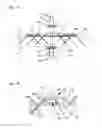
FIG. 7 shows an oblique view of a connecting device according to the invention with coupling fingers as in FIG. 6, wherein the mounting node here has a coupling node, a lower support body and a lower mounting body as well as an upper support body and an upper mounting body.
FIG. 8 shows a sectional side view of the connecting device according to FIG. 7 in the installed state,
FIG. 9 shows a schematically illustrated top view of various use examples or associated embodiments of the connecting device according to the invention for mounting wooden construction elements in the form of panels,
FIG. 10 shows a schematically outlined top view of various examples of use or associated embodiments of the connecting device according to the invention for mounting wooden construction elements in the form of beams,
FIG. 11 shows an oblique view of a connecting device according to the invention that is similar to that in FIG. 8, which is designed for mounting a wooden construction element in the form of a panel on a corner or designed for mounting three wooden construction elements in the form of beams, in pairs enclosing an angle of 45°,
FIG. 12 shows an oblique view of a connecting device according to the invention, which is designed for mounting two wooden construction elements in the form of beams, which abut in flush fashion,
FIG. 13a shows a sectional side view of a connecting device according to the invention in the installed state with a plurality of insulating elements, and
FIG. 13b shows an enlarged detailed view of FIG. 13a within the range of a fastening member block.
DESCRIPTION OF EMBODIMENTS
FIG. 1 shows in a schematic outline a sectional side view of a connecting device 3 according to the invention in an installed state, i.e. mounted on the support 2a and connected to the wooden construction element 1. The mounting node 4 is mounted on the upper end face of the support 2a and attached to the head of the support 2a by means of screw 32. (Of course, other possibilities of fastening the mounting node 4 to the head of the support 2a are also conceivable and provided.)
The coupling arrangement 5 is connected to the mounting node 4 and, in the installed state, projects from the mounting node 4 and comes to lie via its underside on the upper side 1a of the wooden construction element 1 as well as is designed in such a way that it can be connected to the wooden construction element by fastening members 7. Here, basically all known connecting and/or fastening members suitable for connecting wooden construction elements to e.g. metal members come into consideration, such as screw-shaped, pin-shaped, strip-shaped or nail-shaped fastening members, which can be screwed, hammered and/or also (additionally) adhered into the wooden construction element. Brackets or additional fittings can also be provided. They are separately connected to the wooden construction element and are connected to the coupling element according to the invention e.g. via a suitable positive engagement. Full adhesion is also conceivable and provided according to the invention.
In the embodiment shown as a schematic outline in FIG. 1, in particular self-drilling wood screws are provided as fastening members 7, which are screwed through the fastening member bores 9 into the wooden construction element 1.
FIG. 1 shows that, in the installed state, the wooden construction element 1 is mounted on the coupling apparatus 5 in suspended fashion. The support force acting upwards is introduced via the mounting node 4 made of a resilient material. The flow of forces introduced into the mounting node 4 at the comparatively small mounting area is distributed via the fastening members 7 (here: wood screws) arranged in a larger area over a comparatively large volume of the wooden construction element.
FIG. 1 also shows that no further components come to lie on the underside of the wooden construction element. The components on the upper side 1a are covered e.g. in the case of ceiling constructions by the floor structure of the story thereabove.
FIG. 2 shows an oblique view of a connecting device 3 according to the invention, wherein here the coupling arrangement 5 is designed as a circular disk to be produced in an easy and cost-effective way. Of course, other, more complex designs of the coupling arrangement 5—right up to any conceivable free form—are also provided according to the invention.
However, the coupling arrangement 5 shall, in the installed state, (at least with partial areas on the underside thereof) abut on the upper side 1a of the wooden construction element 1 and be connectable to the wooden construction element 1 by fastening members 7. In the embodiment illustrated in FIG. 2, the coupling arrangement 5 also has fastening member bores 9, such that it can be connected by means of screw-shaped, pin-shaped or nail-shaped fastening members 7, such as wood screws, to the wooden construction element 1 (not shown in FIG. 2). In the embodiment shown in FIG. 2, the mounting node 4 is designed in such a way that, in the installed state, it is not the support (not shown herein) that passes through the wooden construction element 1 but the mounting node 4, which can be designed in a particularly resilient way.
FIG. 3 shows a sectional side view of a connecting device 3 according to the invention, in which coupling arrangement 5 has (elongate) coupling fingers 8, which are pivotally connected to the mounting node 4 via a respective joint and can be pivoted between a space-saving packaging or transport position (rest position) and the installation position (i.e. the work position in the installed state), which is advantageous for both packaging, storage as well as transport and the on-site handling and assembly at the building site. In the installed position, the coupling fingers 8 run parallel to the coupling plane 6. In the packaging or transport position, the coupling fingers 8 run parallel to the vertical axis 4f of the mounting node 4, and the coupling fingers 8 can thus be folded into a space-saving “bundle”.
FIG. 4 shows a further embodiment of a connecting device 3 according to the invention with pivotable coupling fingers 8. In contrast to FIG. 3, the coupling fingers 8 in FIG. 4 run parallel to the coupling plane in both the installed position and the packaging or transport position. However, here too, the coupling fingers 8 can be pivoted in such a way that, in the packaging or transport position, they are placed parallel to one another as a space-saving “bundle” (dashed illustration).
FIG. 5a shows an oblique view of a section of a connecting device 3 according to the invention. The coupling arrangement 5 is designed as a coupling finger 8. The coupling arrangement 5 or the coupling finger 8 is designed in such a way that it can be connected to the wooden construction element 1 by means of screw-shaped, pin-shaped or nail-shaped fastening members 7 and has a fastening member bore 9, which defines the position, the angle of inclination θ and the horizontal angle φ of the fastening member axis 7c.
The direction vector s of the fastening member axis 7c and the normal vector n enclose the angle of inclination θ towards the underside of the coupling arrangement 5.
The radial vector r runs from the center O of the mounting node 4 that is situated in the coupling plane 6 to the point of intersection P, in which the fastening member axis 7c intersects the coupling plane 6 (i.e. r=P−O, wherein P and O are the position vectors of said points). The vector s′ is the projection of the direction vector s of the fastening member axis 7c on the coupling plane 6, and, together with the radial vector r, encloses the horizontal angle φ, which can assume any value between 0° and 360°. If—as is common practice—φ is associated clockwise with positive values and counterclockwise with negative values, the horizontal angle φ can assume any value between 0° and ±180°.
FIG. 5b shows byway of diagram the projection of the points, vectors and angles on the coupling plane 6, as illustrated in FIG. 5a. The consideration of FIG. 5a and FIG. 5b in combination shows that the horizontal angle φ can assume any values between 0° and 360° or between 0° and ±180°. As explained below, the horizontal angles φ can, however, assume values in the quadrant between −45°and +45° or in the quadrant between +135° and −135°—in particular in embodiments in which the coupling arrangement 5 is designed in the form of elongate coupling fingers 8.
FIG. 6 shows a top view of a connecting device 3 according to the invention, in which the coupling arrangement 5 consists of six radially arranged coupling fingers 8, each having fastening member blocks 11. In the installed state, the fastening members 7 pass through the fastening member blocks 11, which are designed in such a way that they basically (i.e. on the basis of typical tolerances) define the position of the fastening member axes 7c and/or the respective angle of inclination θ and the respective horizontal angle φ. In this FIG. 6, the fastening members 7 (or the fastening member axes 7c) are shown as lines in simplified symbolized fashion.
The illustrated arrangement, in which the fastening members 7 do not extend below the (comparatively narrow) coupling fingers 8 but are respectively “twisted” in relation to the longitudinal axes 8a of the coupling fingers about a horizontal angle φ (i.e. φ unequal 0° and unequal ±180°, effect a more widely distributed load introduction via the fastening members 7 into the wooden construction element 1 and into a volume range which is markedly larger than the one directly below the coupling fingers 8.
FIG. 7 shows an oblique view of a connecting device 3 according to the invention with coupling fingers 8 as in FIG. 6. In the embodiment shown in FIG. 7, the mounting node 4 includes the following:
-
- a coupling node 4a, to which the coupling arrangement 5 (or here: coupling finger 8) is connected,
- a lower support body 4b projecting downwards in the installed state, which, in the installed state, is connected to the coupling node 4a,
- a lower support body 4c, which, in the installed state, is connected to the lower support body 4b and is designed for the mounting or the assembly on the (lower) support 2a,
- an upper support body 4d projecting upwards in the installed state, which, in the installed state, is connected to the coupling node 4a,
- an upper mounting body 4c, which, in the installed state, is connected to the upper support body 4d and is designed for the mounting or the assembly on the upper support 2a.
In the embodiment shown in FIG. 7, the lower mounting body 4c and the upper mounting body 4e are furthermore designed in such a way that—based on the respective mounting area—they can be connected to the respective support 2a, 2b by means of obliquely guided screws 32.
FIG. 7 also shows that the obliquely guided fastening members 7 (here: wood screws) are come to lie outside the volumes which are disposed below the—comparatively narrow—coupling fingers, which improves the load introduction into the wooden construction element 1 (not shown herein).
FIG. 8 is a sectional side view of a connecting device 3 similar to that in FIG. 7 in the installed state. The mounting node 4 and/or, in this case, its component, mounting body 4c, is mounted on the lower support 2a and attached to the head of the lower support 2a by means of screws 32.
The lower support body 4b is detachably connected to the mounting body 4c via a screw connection. The lower support body passes through the wooden construction element 1 and is detachably connected to the coupling node 4a via a screw connection. The coupling node 4a is detachably connected to the lower support body 4b via a screw connection and protrudes upwards to the upper mounting body 4e, which is detachably connected to the upper support body via a screw connection.
The upper support 2b is mounted on the upper mounting body 4e and attached by means of screws 32. The coupling fingers 8 are connected to the coupling node 4a and come to lie on the upper side of the wooden construction element 1 and are themselves connected to the wooden construction element 1 by the fastening members 7 (here: self-drilling wood screws). The angle θ′ shown in FIG. 8 is the projection of the angle of inclination θ of the fastening member axis on the image and/or sectional plane of the figure.
It is also possible for the lower mounting body 4c and/or the upper mounting body 4e to be designed in such a way that they do not require any fixation on the respective support 2a, 2b by the screws 32 or by other fastening members. This can be achieved e.g. by designing the mounting bodies 4c, 4e in such a way that they are laterally fixed to the support axis by a lateral positive engagement with the respective support 2a, 2b, e.g. via a collar enclosing the support head or by spikes penetrating the head. A vertical fixation is often unnecessary due to the weight force occurring in structures.
In the embodiment shown in FIG. 8, the lower mounting body 4c is designed in such a way that it does not only serve to be mounted on the lower support 2a or a foundation but, in turn, also serves as a mounting for the wooden construction element 1. In a combined consideration with the above described fact that components 4a-4e o the mounting node 4 are detachably connectable to one another—this is particularly advantageous as regards the assembly: First, the lower mounting body 4c and the lower support body 4b are attached to the head of the support 2a. Then, the wooden construction element 1 can be mounted provisionally on the lower support body 4c and is already in the installation position without the aid of e.g. auxiliary supports or frameworks. Thereafter, the coupling node 4a is attached from above with the coupling arrangement 5 to the lower support body 4b and the coupling arrangement 5 is subsequently connected to the wooden construction element 1. This assembly possibility from above and without e.g. auxiliary supports is considerably more convenient and safer especially in ceiling constructions than any assembly from below.
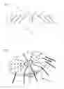
FIG. 9 shows in a schematically outlined top view various examples of use or associated embodiments of the connecting device 3 according to the invention for mounting wooden construction elements in the form of panels—hereinafter referred to as “panels”:
-
- Arrow 41 points to a mounting according to the invention in the panel center of panel 1.
- Arrow 42 points to a mounting according to the invention at the corner of panel 1.2.
- Arrow 43 points to a mounting according to the invention at an edge of panel 1.3.
- Arrow 44 points to a mounting according to the invention at the T-joint of panels 1.3 and 1.4, situated at the edge.
- Arrow 45 points to a mounting according to the invention at the longitudinal joint of panels 1.2 and 1.3.
Arrow 46 points to a mounting according to the invention at the corner of the four panels 1, 1.2, 1.3 and 1.4.
It is clear from this illustration that not only one panel but a plurality of panels can be mounted by the connecting device according to the invention and that in the case of designs having a lower support body 4b this support body 4b does not necessarily pass through the wooden construction element 1 but can also come to lie on an edge (plus corner) of the wooden construction element 1.
FIG. 10 shows in a schematically outlined top view various examples of use or associated embodiments of the connecting device 3 according to the invention for mounting wooden construction elements in the form of beams—hereinafter referred to as “beam”.
-
- Arrow 47 points to a mounting according to the invention at the left-hand end of beam 1.
- Arrow 48 points to a mounting according to the invention approximately in the center of beam 1.
- Arrow 49 points to a mounting according to the invention at the joint of beam 1 and beam 1.2.
FIG. 11 show's an oblique view of a connecting device 3 according to the invention, designed in a way similar to that in FIG. 7 for mounting a wooden construction element in the form of a panel at a corner or designed for mounting three wooden construction elements in the form of beams, which in pairs enclose an angle of 45° each.
FIG. 12 shows an oblique view of a connecting device 3 according to the invention, which is designed for mounting two wooden construction elements which abut in flush fashion.
FIG. 13a shows a sectional side view of a connecting device according to the invention in the installed state, which has insulating elements 20a-20e.
FIG. 13b shows an enlarged detailed view of FIG. 13a in the vicinity of a fastening member block 11.
FIGS. 13a and 13b show that the coupling arrangement 5 comes to lie between the fastening member blocks 11 and the wooden construction element 1 so as to be quasi “mounted in floating fashion” via the insulating elements 20b and 20c. The coupling arrangement 5 is not connected to the wooden construction element 1 in a rigid or inflexible way but in an elastically damped way and is thus sound-absorbing.
In the present application and the claims, the terms “connect”, “connected”, “connection” do not only refer to rigid or inflexible connections but also to damped and elastic connections or between the respective members/components. The same also applies, mutatis mutandis, to the terms “attach”, “assembly”, “mount”, “mounting”, “fasten” and “fastening”.
A consideration of the present explanations and the entire drawings in combination also discloses:
-
- The formation of the components of the invention is not limited to the simple forms shown in the drawings
- In particular the coupling arrangement 5 or the coupling fingers 8 can be formed in many ways and can be optimized in many ways in particular with respect to their load-bearing capacity and/or with respect to the relationship between use of material and load-bearing capacity.
- The invention can be implemented in such a way that it can be disassembled into all its individual components.
- The fastening member blocks 11 do not necessarily have to be connected a priori to the coupling arrangement 5 or to the coupling fingers 8 but can be designed as separate members which come to lie according to the invention in the assembled state for the first time.
- Likewise, the insulating elements 20a-20e do not have to be connected a priori to other components but can be designed as separate members which come to lie according to the invention in the installed state for the first time.
For reasons of ease of presentation, the upper side 1a of the wooden construction element 1 has been assumed to be a continuously flat surface in all explanations and drawings. Of course, it is e.g. also possible to provide the wooden construction element with recesses which allow a recessed installation of the coupling arrangement 5.
Furthermore, it is also provided to design the connecting arrangement in such a way that a “cambered installation” as referred to among experts becomes possible: In this case, the coupling arrangement 5 is designed in such a way that prior to the assembly of the fastening members 7 the underside 5a thereof does not yet abut on the wooden construction element 1 but is forced to do so by the attached fastening members 7 for the first time. It is thus possible to introduce tensions into the wooden construction element 1, which counteract e.g. the weight-related sag between two mountings.
LIST OF REFERENCE SIGNS
- 1 wooden construction element
- 1a upper side 1a of the wooden construction element 1
- 1b underside 1b of the wooden construction element 1
- 1.2 second wooden construction element
- 1.3 third wooden construction element
- 1.4 fourth wooden construction element
- 2a (lower) support
- 2b additional, upper support
- 3 connecting device
- 4 mounting node
- 4a coupling node
- 4b lower support body
- 4c lower mounting body
- 4d upper support body
- 4e upper mounting body
- 4f vertical axis of the mounting node 4
- 5 coupling arrangement
- 5a underside 5a of the coupling arrangement 5
- 5b upper side 5b of the coupling arrangement 5
- 6 coupling plane (defined by the underside 5a of the coupling arrangement 5 or, in the installed state, by the upper side 1a of the wooden construction element 1)
- 7 fastening member
- 7a coupling segment of the fastening member 7
- 7b fastening member head
- 7c fastening member axis
- 8 coupling finger
- 8a longitudinal axis 8a of the coupling finger 8
- 9 fastening member bore (for the fastening member 7)
- 10 head support (for the head of the fastening member 7)
- 11 fastening member block
- 11a underside 11a of the fastening member block 11
- 11b upper side 11b of the fastening member block 11
- 20a-e insulating element
- 32 screw (for attaching the mounting body 4c, 4e to the supports 2a, 2b)
- 41-46 embodiment and example of use for mounting wooden construction elements 1 in the form of panels
- 47-49 embodiment and example of use for mounting wooden construction elements 1 in the form of beams
- θ angle of inclination θ of the fastening member axis 7c
- θ′ projection θ′ of the angle of inclination θ on the image plane of the respective drawing
- φ horizontal angle φ of the fastening member axis 7c
- n normal vector n on the underside 5a of the coupling arrangement 5
- O center O of the mounting node 4 that is disposed in the coupling plane 6 (position vector)
- P point of intersection between the fastening member axis 7c and the coupling plane 6 (position vector)
- r radial vector r, runs from O to P (i.e. r=P−O)
- s direction vector s of the fastening member axis 7c
- s′ direction vector s′ of the projection of the fastening member axis 7c on the coupling plane 6
Claims
1. A connecting device (3) for mounting a wooden construction element (1), in particular in the form of a panel or beam, on a support (2a), the connecting device (3) comprising
a mounting node (4), which is designed for mounting the connecting device (3) on the support (2a) and
a coupling arrangement (5), which is connected to the mounting node (4) and which, in the installed state, while projecting from the mounting node (4) on an upper side (1a) of the wooden construction element (1), can be connected to the latter using fastening members (7), which at least partially pass through the wooden construction element (1), wherein the mounting node (4) and the coupling arrangement (5) are each produced from a material which has a higher strength than that of the wooden construction element (1).
2. The connecting device (3) according to claim 1, wherein the coupling arrangement (5) has at least one coupling finger (8), which is adjustably connected to the mounting node (4), in particular in pivotal fashion via a joint, and is adjustable between a space-saving rest position and a work position.
3. The connecting device (3) according to claim 1 or 2, wherein
the coupling arrangement (5) is designed in such a way that it can be connected to the wooden construction element (1) in each case along a fastening member axis (7c) by means of screw-shaped, pin-shaped or nail-shaped fastening members (7), in particular a self-drilling wood screw,
the coupling arrangement (5) has fastening member bores (9), which determine the position and direction of the fastening member axes (7c), wherein these fastening member bores (9) are designed in such a way that, in the installed state,
the fastening member axis (7c) encloses together with a normal vector n extending from the underside (5a) of the coupling arrangement (5) one angle of inclination θ each, which is 0° to 80°, 30° to 60° or about 45°, and
a direction vector s′ of the projection of the fastening member axis (7c) on a coupling plane (6) defined by the underside (5a) of the coupling arrangement (5) encloses together with a radial vector r lying in the coupling plane (6) a horizontal angle φ,
wherein the radial vector r runs from a center O of the mounting node (4) that is disposed in the coupling plane (6) to a point of intersection P, in which the fastening member axis (7c) intersects the coupling plane (6), and
wherein the horizontal angle φ is 0° to ±180° or 45° to 135° or −45° to −135°.
4. The connecting device (3) according to any of the preceding claims, wherein the connecting device (3) has at least one fastening member block (11), which, in the installed state, is arranged on an upper side (5b) of the coupling arrangement (5),
and has one or more fastening member bores (9), which determine the position and direction of the fastening member axes (7c).
5. The connecting device (3) according to any of the preceding claims, wherein the mounting; node (4) comprises
a coupling node (4a), to which the coupling arrangement (5) is connected in the installed state,
a lower support body (4b), which, in the installed state, projects downwards and which, in the installed state, is connected to the coupling node (4a) and passes through the wooden construction element (1),
a lower mounting body (4c), which, in the installed state, is connected to the lower mounting body (4b) and is designed for mounting or the assembly on the support (2a).
6. The connecting device (3) according to claim 5, wherein the mounting node (4) additionally comprises
an upper support body (4d), which, in the installed state, projects upwards and which, in the installed state, is connected to the coupling node (4a), and
an upper mounting body (4e), which, in the installed state, is connected to the upper support body (4d) and is designed for mounting a further support (2b).
7. The connecting device (3) according to claim 5 or 6, wherein
the coupling node (4a), the lower support body (4b) and the lower mounting body (4c) are designed in such a way that the distance between the coupling node (4a) and the lower mounting body (4c) can be adjusted and/or
the coupling node (4a), the upper support body (4d) and the upper mounting body (4e) are designed in such a way that the distance between the coupling node (4a) and the upper support body (4e) can be adjusted.
8. The connecting device (3) according to any of the preceding claims, wherein a plurality of the components and/or members of the connecting device (3), which, in the installed state, are connected to one another, are all detachably connected to one another, in particular via screw, clamp, bolt, splint or bayonet connections.
9. The connecting device (3) according to any of the preceding claims, wherein the connecting device (3) has a structure-borne sound insulating unit (20a˜20e), which is designed in such a way that, in the installed state, the structure-borne sound insulating transmission is insulated or attenuated from the wooden construction element (1) via the connecting device (3) to the lower support (2a) and/or to the upper support (2b).
10. The connecting device (3) according to any of the preceding claims, wherein the connecting-device (3) is designed in such a way that, in the installed state, at least part of the flow of forces is passed via at least one insulating element (20a˜20e) in each case, which is designed for insulating or attenuating the structure-borne sound transmission.
11. The connecting device (3) according to any of the preceding claims, wherein, in the installed
state, the connecting device (3) comprises at least one of the following insulating elements (20a˜20e)
an insulating element (20a), which is arranged between the upper side (1a) of the wooden construction element (1) and the underside (5a) of the coupling arrangement (5) and/or
an insulating element (20b), which is arranged between the upper side (5b) of the coupling arrangement (5) and an underside (11a) of the fastening member block (11) and/or
an insulating element (20c), which is arranged between the underside (1b) of the wooden construction element (1) and the lower mounting body (4c) and/or
an insulating element (20d), which is arranged between the mounting node (4) and the lower support (2a) or between the lower support body (4c) and the lower support (2a) and/or
an insulating element (20e), which is arranged between the mounting node (4) and the upper support (2b) or between the upper support body (4e) and the upper support (2b).
12. A wooden construction arrangement having a connecting device (3) according to any of the preceding claims, comprising a support (2a) and a wooden construction element (1), which is made in particular from cross laminated timber, wherein the connecting device (3) is mounted on the support (2a) and the wooden construction element (1) is attached to the connecting device (3) in suspended fashion or the connecting device (3) is connected to the wooden construction element (1) on the upper side (1a) thereof.
13. A structure comprising a wooden construction arrangement according to claim 12.
Images & Drawings included:


Sources:
- United States Patent and Trademark Office - verify current appl. status at the USPTO↗
Recent applications in this class:
- » 20250003210 2025-01-02
Framing Bracket - » 20240360660 2024-10-31
SUBFLOOR PILE FIXING CONNECTOR AND RELATED SYSTEMS - » 20240295113 2024-09-05
OUTDOOR FRAMING MODULE - » 20240110372 2024-04-04
BUILDING AND CONSTRUCTION APPARATUS AND METHOD - » 20230358032 2023-11-09
Stack-it bracket - » 20230203802 2023-06-29
Column Cap - » 20230193618 2023-06-22
Connector device, system and method for constructing a roof for a building - » 20230091125 2023-03-23
POST AND BEAM STRUCTURE AT A MULTI-HEIGHT OPENING PORTION - » 20230048980 2023-02-16
Stack-It Bracket - » 20220403643 2022-12-22
Tension Tie
Recent applications for this Assignee:
- » 20220164694 2022-05-26
Tunable coupling between a readout cavity and a parametric amplifier to enhance qubit measurements - » 20200033355 2020-01-30
Full length kinase activity-conformation reporter - » 20180047550 2018-02-15
Method and apparatus for chemical ionization of a gas mixture - » 20180009689 2018-01-11
Method for determining the amount of anammox bacteria - » 20160325230 2016-11-10
Electrochemical cell - » 20140371306 2014-12-18
Pharmaceutical compositions comprising lignans and their derivatives for treating hyperplastic diseases - » 20140033700 2014-02-06
Hydraulic energy store - » 20130053438 2013-02-28
PHARMACEUTICAL COMPOSITIONS COMPRISING LIGNANS AND THEIR DERIVATIVES FOR THE MEDICAL MANAGEMENT OF ANGIOGENESIS AND HYPOVASCULARITY - » 20110290995 2011-12-01
Apparatus and method for trapping charged particles and performing controlled interactions between them - » 20110189252 2011-08-04
Pharmaceutical compositions comprising lignans and their derivatives for treating hyperplastic diseases