Intermediate Wood Wall Support System called Straight Wall
US20180371752A1
2018-12-27
16/016,587
2018-06-23
Abstract:
A Wood Wall Support System as a manner to straighten a wall surface and provide a good structure to place drywall, paneling and various finishes on a vertical planar wall surface. It is designed to keep wood walls strong, even and vertically straight by creating a flat plane for the wall finishes. A long “T” configuration is applied generally in the center of the length of the stud and can be applied to the wall as it is in a horizontal position or after the studs are vertical. This system can be used in both Residential and Commercial wood frame wall applications.
Interested in similar patents?
Get notified when new applications in this technology area are published.
Classification:
E04B2/709 » CPC main
Walls, e.g. partitions, for buildings; Wall construction with regard to insulation; Connections specially adapted to walls walls of framework or pillarwork Load-bearing ; Walls incorporating load-bearing elongated members with elongated members of wood with supporting function obturation by means of longitudinal elements with a plane external surface
E04B2/70 IPC
Walls, e.g. partitions, for buildings; Wall construction with regard to insulation; Connections specially adapted to walls walls of framework or pillarwork Load-bearing ; Walls incorporating load-bearing elongated members with elongated members of wood
Description
CROSS-REFERENCE TO RELATED APPLICATIONS
This application claims the benefit of U.S. Provisional Patent Application with Ser. No. 62/524,425 filed Jun. 23, 2017, by Bruce Tiefel and entitled Intermediate Wood Wall Support System called Straight Wall.
FIELD OF INVENTION
This invention relates to an Intermediate Wood Wall Support System called Straight Wall. Particularly this is a manner to straighten a wall surface and provide a good structure to place drywall, paneling and various finishes on a vertical planar wall surface. The present invention relates to a system that pertains to straightening bowed studs and using the straight wall system to make them commonly flush at the medial/mid area of the wall. It provides a straight, even and more rigid framing base for the wall finish. The present invention relates generally to the framing of walls in new construction and in the remodeling of buildings and, more particularly, to a relatively simple system to align and support members such as studs forming walls, or window and door openings in the framing for such new construction or in buildings being remodeled to establish and provide a common, straight and even or planar for affixing any desired exterior finishing members such as paneling, wallboard, sheetrock, and the like thereto.
FEDERALLY SPONSORED RESEARCH
None.
SEQUENCE LISTING OR PROGRAM
None.
BACKGROUND—FIELD OF INVENTION AND PRIOR ART
As far as known, there are no Intermediate Wood Wall Support System called Straight Wall or the like. It is believed that this product/system is unique in its design and technologies.
This background as typical wall construction can be useful. Most commonly walls are built lying flat (horizontal) and then raised to a vertical position. Studs in the wall are tied together by a top and bottom plate that runs perpendicular to the studs. Typical is two (2) nails through each, the top and bottom plates into each stud. Hence, each stud is held in place by four (4) nails and held only at each end by two (2) nails. Normally, after the studs are nailed in place, a second or double plate is added to the top of the wall. A length of wall may contain only single studs that are typically spaced at 16, 24 or 19 3/16 inches on center, or the wall may contain multiple studs together to form corners, leads, door or window header supports (known as jacks or doubles) or beam supports, in the wall, along with single studs. Regardless, typically the studs are attached at the top and bottom of the wall only regardless of the length of the stud, or in other words, the height of the wall.
PRIOR ART
A novelty search reveal no prior art like the Straight Wall. The search revealed:
A. U52002/0005023 by Ford was published in 2002 for a patent application named Attachment and Devices For Straightening, Squaring, And Aligning, Support Members To Members To Receive Exterior Finishing Members And Methods Therefor. This showed sized and shaped attachments made of suitable materials and having a predetermined thickness for straightening and replacing studs, joists and rafters, squaring of openings and for aligning a plurality of the studs, joists and rafters in the framing for a building to provide a planar application surface to which exterior finishing members can be affixed. The attachments have sized and spaced openings thereon operatively associated by frictional engagement with fastening members each having a slidable member thereon to enable the attachments or devices to be adjustably fastened to a given stud, joist or rafter so a plurality of such adjusted attachments or any replacement attachments can be aligned with each other to provide the planar application surface. Methods are provided to align a multiplicity of adjoining studs, joists or rafters, to square and to square and align openings with such attachments to provide the planar application surfaces.
B. U.S. Pat. No. 5,662,310 by Carson Sr. was issued in 1997 for a Stud Adjuster Apparatus. This device is a star stud adjuster apparatus including an adjuster. The adjuster includes a J-shaped support with an exterior surface having a pair of brackets projecting therefrom. The adjuster includes a handle with a forked end that is capable of being positioned between the brackets. Also provided is a cylindrical member. The cylindrical member has a pair of side surfaces with each having a ratchet integral thereto and projecting therefrom. The cylindrical member is positionable between the forked ends and held in place with an axial rod. Banding material is included. The banding material is weaved around a plurality of bowed studs and is secured by a nail to one of the bowed studs. The banding material is capable of being positioned around the cylindrical member between the forked end when the adjuster is positioned on an opposite stud.
C. U.S. Pat. No. 4,620,691 by Waters Jr. was issued in 1986 and called a Broad Straightening Device Use with Roof Planks. It demonstrates a board straightening device which embodies levers to expand a concentric piping arrangement, one end of which is fixed on a joist, rafter stud, or other board supporting member, and the other end is placed against a crooked board, such as decking or siding, which is being nailed across the board supporting member. The device includes a cleated foot for gripping the board supporting member, the foot being attached to a pipe member which fits concentrically with another pipe member to which is attached the head or pushing end of the device. A lever arrangement connecting the two pipe members causes them to relatively displace when a lever handle is pushed toward the device. A head attachment, configured to the shape of the board to minimize damage, pushes against and straightens the crooked board for nailing. Limiting and adjusting means for displacement and leverage may be used. A cleated plate with cleat members protruding at approximately a forty-five degree angle from the foot may fix the foot on the board supporting member
D. U.S. Pat. No. 4,441,300 by Varon et al. issued in 1984 for a device called a Bracket Support For a Wall Studs. Here is divulged a bracket retaining and support structure for cooperative engagement with a wall stud and adapted for receipt in passageways disposed thereon of the hook ends of support brackets for shelves or the like. The bracket support structure includes a pair of oppositely disposed elongate extruded metal members having respective matingly engageable tongue and groove portions to enable assembly of the channel members together to form the support structure. An elongate metal bar provided with said passageways along the length thereof is retained by said support structure in a slot formed between said channel members; a pair of closely spaced forwardly extending flanges on the channel members form an entranceway in the support structure opening to the passageways on the metal bar to permit insertion of the hook ends of the support brackets within the passageways. In one embodiment, the bar has closely-spaced cut-out portions or notches along the elongate edges thereof and the walls of the bar-receiving slot within which the bar is disposed are deformed into the notches to permanently retain the bar within the slot. In another embodiment, the bar is provided with knurling to bite into the walls of the slot upon permanent assembly of the bar therewithin. In further embodiments, the bar is provided with a rolled groove or a plurality of shear-form protruding portions to bite into the walls of the slot for permanent assembly of the bar therewithin.
The Problem
Anyone who works with framing lumber known that straight lumber is hard to find now days. Most lumber now is cut from new growth trees, timbered from smaller trees and is stored in the elements. Moisture content is high and the lumber tends to turn and twist and bow as it dries. The focus of this invention is on the wall framing materials known as the “studs”. As straight materials get more difficult to obtain, wall heights trends are taller and thus longer materials are being required and utilized. The use of these un-straight and high moisture content materials is resulting in bowed walls and diminished bearing strength. This is making it difficult to apply wall finishes. Foam subsiding materials used now days provide very little, if any, support for the walls, as does the standard drywall. Cracking and breaking of wall finishes is common due to continual movement of the wall as the materials naturally dry out.
Typical Remedies
-
- 1. Do nothing—Suffer with weaker, un-straight walls and periodic wall cracking.
- 2. Straighten the wall—An attempt to straighten the wall before finish materials are applied is commonly attempted. This is typically done by “straight edging” the wall. Cutting the crooked studs and apply a “cleat” or “stiffener” on the side of the studs to attempt to hold them in a straight condition. This procedure is time consuming and typically only the “worse” of the crooked studs are straightened. The result is a temporary straighter stud condition. Normally however the studs can be severely weakened from the process and this type of procedure can cause problems for insulation and mechanical applications to follow, and still the wall may not stay straight as the materials dry out.
Problem Solved—A Solution
A solution to the problem is an Intermediate Wall Support System—Straight Wall. Straight Wall is designed to keep wood walls strong, even and vertically straight if properly applied, creating a flat plane for the wall finishes. Straight Wall is made from galvanized steel in a “T” configuration and can be installed as the wall is fabricated or after the wall is standing. It can be applied to either side of the wall, or a combination of both and is applied generally in the center of the length of the stud. It can be applied to the wall as it is in a horizontal position (preferred) or after it is vertical. Straight Wall is available in two sizes, for 2×4 as well as 2×6 walls, the most common wall vertical stud sizes. The larger size can also be used in walls more than six inches in width. Straight Wall can be used in both Residential and Commercial wood frame wall applications.
SUMMARY OF THE INVENTION
This invention is an Intermediate Wood Wall Support System called Straight Wall for various applications with wood structures. Taught here are the ways this Intermediate Wood Wall Support System can be used for simply and efficiently straightening wood structures.
The preferred embodiment of an Intermediate Wood Wall Support System called Straight Wall is comprised of: (a) at least one “T” made of durable metal further comprised with a pair of angles folded to make the “T”; (b) a series of vertical wood studs which form a wood wall system; and (c) a kerf saw cut into each stud approximately one half the distance between a bottom plate and a top plate of the wood wall system wherein the Straight Wall system uses the “T” placed into the kerf of the studs and the “T” is fastened to the studs whereby each stud is moved to an even position with the adjoining studs and the surface of the studs are vertical to a floor of a building. A further embodiment has the materials for the “T” selected from a list including metal, plastic, composite materials, steel alloys, zinc coated steel, stainless steel, galvanized steel, a modern composite material of plastic and reinforcing fill like carbon, steel, fibers. An alternative embodiment is further comprised of at least one more “T” wherein the first “T” and second “T” overlaps at least two commonly spread studs. And another alternative is an Intermediate Wood Wall Support System called Straight Wall system is comprised of: (a) at least one standard structural “T” made of durable metal; (b) a series of vertical wood studs which form a wood wall system; and (c) a kerf saw cut into each stud approximately one half the distance between a bottom plate and a top plate of the wood wall system wherein the Straight Wall system uses the “T” placed into the kerf of the studs and the “T” is fastened to the studs whereby each stud is moved to an even position and the surface of the studs are vertical to a floor of a building.
The newly invented Straight Wall components for the system can be manufactured at low volumes by very simple means and in high volume production by more complex and controlled systems.
Objects and Advantages
There are several objects and advantages of this Intermediate Wood Wall Support System called Straight Wall. The system has various advantages and benefits:
| Item | Advantages | |
| 1 | Provides a fast straightening system | |
| 2 | Can be installed during the original build | |
| (commonly horizontal), after the walls are placed | ||
| vertical, or on existing walls during remodeling | ||
| 3 | Is rust resistant | |
| 4 | Improves shear strength of the wall | |
| 5 | Maintains vertical compressive strength | |
| 6 | Requires only simple tools | |
| 7 | Can be installed by single worker | |
Finally, other advantages and additional features of the present Intermediate Wood Wall Support System called Straight Wall will be more apparent from the accompanying drawings and from the full description of the components and system. For one skilled in the art of wood structures and wall reinforcement and straightening methods, it is readily understood that the features shown in the examples with this product are readily adapted to other types of wood wall structures and devices.
BRIEF DESCRIPTION OF THE DRAWINGS
The accompanying drawings, which are incorporated in and constitute a part of this specification, illustrate an embodiment of the Intermediate Wood Wall Support System called Straight Wall for various wood wall applications. The drawings together with the summary description given above and a detailed description given below serve to explain the principles of the Straight Wall system. It is understood, however, that the Intermediate Wood Wall Support System called Straight Wall is not limited to only the precise arrangements and instrumentalities shown.
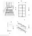
FIGS. 1A through 1D are sketches of the general intermediate wood wall support system for building applications device.
FIGS. 2A through 2D are sketches of the connection “T” for the intermediate wood wall support system with components and features noted.
FIG. 3A through 3F are sketches of the connection “T” in a stud wall using the intermediate wood wall support system.
FIGS. 4A and 4B are sketches of long expanses of the wood wall structure using the intermediate wood wall support system.
FIGS. 5A and 5B are more sketches of a common wooden stud wall with vertical structures and strengthening columns shown.
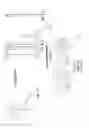
FIGS. 6A through 6D are photos of wood stud walls using the intermediate wood wall support system.
FIGS. 7A though 7E are additional sketches of a wood stud wall using the intermediate wood wall support system.
FIGS. 8A through 8D are examples of prior art used to straighten wood walls.
FIGS. 9A and 9B are more examples of prior art used to straighten wood walls.
REFERENCE NUMERALS
The following list refers to the drawings:
| Ref # | Description | |
| 30 | intermediate wood wall support system for | |
| building applications called straight wall 30 | ||
| 31 | prototype system 31 of intermediate wood wall | |
| support system for building applications 30 | ||
| 40 | straightening “T” 40 of various lengths widths | |
| and depths | ||
| 40A | straightening standard structural “T” 40A of | |
| various lengths, widths, and depths made of a | ||
| rolled standard structural tee | ||
| 41 | kerf leg 41 folded F, two thicknesses of | |
| material | ||
| 44 | nail/screw “holes or apertures” 44 optional | |
| 45 | “T” flats 45 contiguous to a 2 × 4 inch to stud | |
| room surface 63 | ||
| 45A | “T” flats 45A contiguous to a 2 × 6 inch to | |
| stud room surface 63 | ||
| 50 | kerf 50 or saw cut into stud | |
| 51 | nails/screws 51 | |
| 60 | vertical 2 × 4 inch stud 60 | |
| 60A | vertical 2 × 6 inch stud 60A | |
| 61 | top plate 61 | |
| 61A | double plate 61A (second top plate that ties | |
| into other walls | ||
| 62 | bottom plate 62 | |
| 63 | stud surface 63 next to room | |
| 65 | lintel/header 65 | |
| 66 | cleat 66 | |
| 67 | jack trimmer/cripple/stiffener 67 | |
| 69 | spacer or block 69 | |
| 70 | wall framing structure 70 comprised of vertical studs 60 | |
| and horizontal top plates 61, 61A and bottom plates 62 | ||
| when assembled as wall and ready for wall finishes | ||
| (drywall, plaster, paneling, etc.) | ||
| 71 | corner 71 | |
| 72 | wall lead 72 | |
| 73 | beam or load support 73 | |
| 73A | beam or load support 73A with beam pocket 74A | |
| 74 | beam pocket 74 | |
| 77 | window or door double 77 | |
| 80 | Prior art 80 US application 2002/0005023 | |
| 81 | Prior art 81 U.S. Pat. No. 5,662,310 | |
| 82 | Prior art 82 U.S. Pat. No. 4,620,691 | |
| 83 | Prior art 83 literature showing cross member additions | |
| and reinforcement | ||
| w | width w of side angle of “tee” 40 | |
| W | width W across full top of “tee” 40 - 2 of the angles | |
| D | depth D of the “tee” 40 | |
| F | fold F of the two legs 41 of the “tee” 40 | |
| L | length L of the “tee” 40 | |
| O | overlap O of two of the “tees” 40 | |
DETAILED DESCRIPTION OF PREFERRED EMBODIMENT
This invention relates to an Intermediate Wood Wall Support System called Straight Wall. Particularly this is a manner to straighten and strengthen a wall and provide a good structure to place drywall, paneling and various finishes on a flat planar wall. The present invention relates to a system that pertains to straightening uneven, bowed studs and using the straight wall system to make them commonly flush at the medial point. The present invention relates generally to the framing of walls in new construction and in the remodeling of buildings and, more particularly, to a relatively simple system to straighten and support members such as studs forming walls, or window and door openings in the framing for such new construction or in buildings being remodeled to establish and provide a common, straight and even planar frame work for affixing any desired exterior finishing members such as paneling, wallboard, sheetrock, and the like thereto.
The advantages for the Intermediate Wood Wall Support System called Straight Wall 30 are listed above in the introduction. Succinctly the benefits are that the device:
-
- A. Provides a fast straightening system;
- B. Can be installed during the original build (commonly horizontal), after the walls are placed vertical, or on existing walls during remodeling Is rust resistant;
- C. Improves sheer strength of wall;
- D. Maintains vertical compressive strength;
- E. Requires only simple tools; and
- F. Can be installed by single worker.
The preferred embodiment of an Intermediate Wood Wall Support System 30 called Straight Wall is comprised of: (a) at least one “T” made of durable metal further comprised with a pair of angles folded to make the “T”; (b) a series of vertical wood studs which form a wood wall system; and (c) a kerf saw cut into each stud approximately one half the distance between a bottom plate and a top plate of the wood wall system wherein the Straight Wall system uses the “T” placed into the kerf of the studs and the “T” is fastened to the studs whereby each stud is moved to a common and even position and the surface of the studs are vertical to a floor of a building. A further embodiment has the materials for the “T” selected from a list including metal, plastic, composite materials, steel alloys, zinc coated steel, stainless steel, galvanized steel, a modern composite material of plastic and reinforcing fill like carbon, steel, fibers. An alternative embodiment is further comprised of at least one more “T” wherein the first “T” and second “T” overlaps at least one commonly spread studs. And another alternative is an Intermediate Wood Wall Support System called Straight Wall system is comprised of: (a) at least one standard structural “T” made of durable metal; (b) a series of vertical wood studs which form a wood wall system; and (c) a kerf saw cut into each stud approximately one half the distance between a bottom plate and a top plate of the wood wall system wherein the Straight Wall system uses the “T” placed into the kerf of the studs and the “T” is fastened to the studs whereby each stud is moved to a even position and the surface of the studs are vertical to a floor of a building.
There is shown in FIGS. 1-9 a complete description and operative embodiment of the Intermediate Wood Wall Support System called Straight Wall. In the drawings and illustrations, one notes well that the FIGS. 1-9 demonstrate the general configuration and use of this product. The various example uses are in the operation and use section, below.
The accompanying drawings, which are incorporated in and constitute a part of this specification, illustrate an embodiment of the Straight Wall system 30 that is preferred. The drawings together with the summary description given above and a detailed description given below serve to explain the principles of the Intermediate Wood Wall Support System called Straight Wall 30. It is understood, however, that the Straight Wall system 30 is not limited to only the precise arrangements and instrumentalities shown. Other examples straightening of wood wall structures and the like are still understood by one skilled in the art of wood structures and their wall reinforcement and straightening methods that this system is readily adapted to other types of wood wall structures and devices within the scope and spirit shown here.
FIGS. 1A through 1D are sketches of the general intermediate wood wall support system 30 for building applications device. Demonstrated are: an intermediate wood wall support system for building applications called straight wall 30; a prototype system 31 of intermediate wood wall support system for building applications 30; a straightening “T” 40 of various lengths widths and depths; and optional holes or apertures 44 to start nails or screws 50.
FIGS. 2A through 2D are sketches of the connection “T” for the intermediate wood wall support system 30 with components and features noted. Depicted components and features in these figures are: a straightening “T” 40 of various lengths, widths, and depths; a straightening standard structural “T” 40A of various lengths, widths, and depths made of a rolled structural tee; a kerf leg 41 folded F, two thicknesses of material; a nail/screw “holes or apertures” 44 optional; a “T” flats 45 contiguous to 2×4 inch stud room surface 63; a “T” flats 45A contiguous to a 2×6 inch to stud room surface 63; a long straighten “T” 40; a kerf 50 or saw cut into stud; a nails/screws 51; a width w of side angle of “T” 40; a width W across full top of “T” 40—2 of the angles; a depth D of the “T” 40; a fold F of the two legs 41 of the “T” 40; a length L of the “T” 40; and the fold F of the two legs 41 of the “T” 40. The initial design of Straight Wall is manufactured from twenty gage (20 GA) galvanized or zinc coated steel, cold formed to a “T” configuration (as per the attached drawings). Ideal length is approximately twelve feet one and one half inches long (12′-1½″). One skilled in the art of materials realizes that a material resistant to corrosion, especially rusting, is preferred. This means a ferrous based compound needs coating, plating (like galvanized) or a special alloy steel or stainless steel. Likewise, a modern composite material of plastic and reinforcing fill like carbon, steel, fibers and the like can be appropriate materials for the “T” 40 and standard structural “T” 40A. A standard structural “T” 40A is one that has been manufactured by casting, molding, or rolling the Tee (T-shaped cross-section) into its final size of the leg (vertical) and flat (top, horizontal). Originally steel or iron rolled from bars, the standard Tee 40A can also be cast metal or molded plastic or composite materials.
FIG. 3A through 3F are sketches of the connection “T” in a stud wall using the intermediate wood wall support system. Portrayed in these views, one sees an intermediate wood wall support system for building applications called “straight wall” 30; a straightening “T” 40 of various lengths widths and depths; a kerf 50 or saw cut into stud; a nails/screws 51; a vertical 2×4 inch stud 60; vertical 2×6 inch stud 60A; a top plate 61; double plate 61A (second top plate that ties into other walls; a bottom plate 62; a cleat 66; and a jack or trimmer/cripple/stiffener 67. One notes in FIGS. 3E and F the option to use side studs 60 or cleats 66 with the kerf 50 to allow a double stud or beam or load support 73 to remain un-cut without a kerf 50.
FIGS. 4A and 4B are sketches of long expanses of the wood wall structure using the intermediate wood wall support system 30. In these sketches are provided: a straightening “T” 40 of various lengths widths and depths; a kerf leg 41 folded; two thickness of material; a vertical stud 60; a top plate 61; a double plate 61A (second top plate that ties into other walls; a bottom plate 62; a lintel/header 65; a jack or trimmer/cripple/stiffener 67; a wall framing structure 70 comprised of vertical studs 60 and horizontal top plates 61 and bottom plates 62 when assembled as wall and ready for wall finishes (drywall, plaster, paneling, etc.); an overlap O of two of the “T” 40; a corner 71; a wall lead 72; a beam or load support 73; and a window or door double 77.
FIGS. 5A and 5B are more sketches of a common wooden stud wall with vertical structures and strengthening columns shown. One can see the features and components shown are: a vertical stud 60; a top plate 61; a double plate 61A (second top plate that ties into other walls; a bottom plate 62; a jack or trimmer/cripple/stiffener 67; a spacer or block 69; a wall framing structure 70 comprised of vertical studs 60 and horizontal top plates 61 and bottom plates 62 when assembled as wall and ready for wall finishes (drywall, plaster, paneling, etc.); a corner 71; a wall lead 72; a beam or load support 73; beam or load support 73A with beam pocket 74; a beam pocket 74 and a window or door double 77.
FIGS. 6A through 6D are photos of wood stud walls using the intermediate wood wall support system 30. Illustrated here are the following: a prototype system 31 of intermediate wood wall support system for building applications 30; a “T” 40; a vertical stud 60; a top plate 61; a double plate 61A (second top plate that ties into other walls; a bottom plate 62; jack or trimmer/cripple/stiffener 67; an internal room surface 63; and an overlap O of two of the “T”s 40.
FIGS. 7A though 7E are additional sketches of a wood stud wall using the intermediate wood wall support system 30. Displays of these sketches and photos show: a prototype system 31 of intermediate wood wall support system for building applications 30; a long straighten “T” 40 of various lengths; a kerf 50 or saw cut into stud; an overlap O of two of the “T”s 40; and a vertical stud 60.
FIGS. 8A through 8D and FIGS. 9A and 9B are examples of prior art used to straighten wood structural walls. Here former patents, applications and literature for wood structure straightening and reinforcing. Shown and demonstrated are: prior art 80 US application 2002/0005023; prior art 81 U.S. Pat. No. 5,662,310; prior art 82 U.S. Pat. No. 4,620,691; and prior art 83 literature showing cross member additions and reinforcement herein. As can be seen, the Intermediate Wood Wall Support System called Straight Wall 30 is a unique combination and use as described.
The details mentioned here are exemplary and not limiting. Other specific components and manners specific to describing the Straight Wall system 30 may be added, as a person having ordinary skill in the field of wood structures and wall reinforcement and straightening methods, and are readily adapted to other types of wood wall structures and devices.
Operation of the Preferred Embodiment
The Intermediate Wood Wall Support System called Straight Wall 30 has been described in the above embodiment. The manner of how the device operates is described below. One notes well that the description above and the operation described here must be taken together to fully illustrate the concept of the Straight Wall system 30. The preferred embodiment of an Intermediate Wood Wall Support System 30 called Straight Wall is comprised of: (a) at least one “T” 40 made of durable metal further comprised with a pair of angles folded to make the “T”; (b) a series of vertical wood studs 60 which form a wood wall system 70; and (c) a kerf saw cut 50 into each stud approximately one half the distance between a bottom plate 62 and a top plate 61 of the wood wall system wherein the Straight Wall system uses the “T” placed into the kerf of the studs and the “T” is fastened to the studs whereby each stud is moved to a even position and the medial surface of the studs are vertical to a floor of a building. A further embodiment has the materials for the “T” selected from a list including metal, plastic, composite materials, steel alloys, zinc coated steel, stainless steel, galvanized steel, a modern composite material of plastic and reinforcing fill like carbon, steel, fibers. An alternative embodiment is further comprised of at least one more “T” lengths 40 wherein the first “T” 40 and second “T” 40 overlaps at least two commonly spread studs 60 by a pre-determined distance “O” such as 12½ inches, 16 inches, or 24 inches, or a similar conventional stud spread. And another alternative is an Intermediate Wood Wall Support System called Straight Wall system is comprised of: (a) at least one standard structural “T” made of durable metal; (b) a series of vertical wood studs which form a wood wall system; and (c) a kerf saw cut into each stud approximately one half the distance between a bottom plate and a top plate of the wood wall system wherein the Straight Wall system uses the “T” placed into the kerf of the studs and the “T” is fastened to the studs whereby each stud is moved to an even and flush position and the surface of the studs are vertical to a floor of a building.
The Straight Wall system 30 is a solution to the problem is an Intermediate Wall Support System. Straight Wall is designed to keep wood walls strong and vertically straight, creating a flat plane for the wall finishes. Straight Wall is made from a durable material (see above) such as galvanized steel in a “T” configuration and can be installed as the wall is fabricated or after the wall is standing. It can be applied to either side of the wall, or a combination of both and is applied generally in the center of the length of the stud. It can be applied to the wall as it is in a horizontal position (preferred) or after it is vertical. Straight Wall is available in two sizes, for 2×4 as well as 2×6 walls, the most common wall sizes. The larger size can also be used in walls more than six inches in width. Straight Wall can be used in both Residential and Commercial wood frame wall applications. Straight Wall 30 is installed in a prepared “saw kerf” 50, prepared onsite and perpendicular to and across the face of the studs 60 and generally in the center of the length of the stud. Straight Wall “T” 40 is then firmly pressed into the sawn kerf 50 and double nailed or double screwed 51 to each stud 60. Multiple lengths of Straight Wall should be installed to an overlap distance O itself by at least one stud and pieces should be spaced several inches apart to avoid splitting or breaking of the wood stud between the multiple pieces of Straight Wall. The ideal installation time is after the wall is fabricated, straight and squared and still lying flat on the floor and before the sub-siding, if any, is applied. (In the horizontal position) Care should be taken to insure the “kerf” 50 is properly sized for a “tight” fit when the Straight Wall is pressed into it. When properly installed, the structural features of the wall should be enhanced due to the fact each single stud is properly spaced and straight. The installer may prefer not to kerf multiple stud components of the wall (Corners, leads, door/window doubles and beam supports—see FIGS. 3E and 5B). Options for that situation are to kerf only the outer studs of the assembly (either prior to or after assembled) or a short cleat 66 with a kerf 50 can be applied to the side of such component to affix the Straight Wall to it (FIG. 3F). Optimum results will occur when the straight wall runs the entire length of the wall with the exception of door or window openings, if any. Care should be taken during installation, and install Straight Wall at heights and or sides of the wall to avoid conflicts with mechanical and electrical installations or diagonal wall bracing.
With this description it is to be understood that the Intermediate Wood Wall Support System called Straight Wall 30 is not to be limited to only the disclosed embodiment of product. The features of the Straight Wall system 30 are intended to cover various modifications and equivalent arrangements included within the spirit and scope of the description.
While certain novel features of this invention have been shown and described and are pointed out in the annexed claims, it is not intended to be limited to the details above, since it will be understood that various omissions, modifications, substitutions and changes in the forms and details of the device illustrated and in its operation can be made by those skilled in the art without departing in any way from the spirit of the present invention. Without further analysis, the foregoing will so fully reveal the gist of the present invention that others can, by applying current knowledge, readily adapt it for various applications without omitting features that, from the standpoint of prior art, fairly constitute essential characteristics of the generic or specific aspects of this invention.
Unless defined otherwise, all technical and scientific terms used herein have the same meaning as commonly understood by one of ordinary skill in the art to which these inventions belong. Although any methods and materials similar or equivalent to those described herein can also be used in the practice or testing of the present inventions, the preferred methods and materials are now described above in the foregoing paragraphs.
Other embodiments of the invention are possible. Although the description above contains much specificity, these should not be construed as limiting the scope of the invention, but as merely providing illustrations of some of the presently preferred embodiments of this invention. It is also contemplated that various combinations or sub-combinations of the specific features and aspects of the embodiments may be made and still fall within the scope of the inventions. It should be understood that various features and aspects of the disclosed embodiments can be combined with or substituted for one another in order to form varying modes of the disclosed inventions. Thus, it is intended that the scope of at least some of the present inventions herein disclosed should not be limited by the particular disclosed embodiments described above.
The terms recited in the claims should be given their ordinary and customary meaning as determined by reference to relevant entries (e.g., definition of “plane” as a carpenter's tool would not be relevant to the use of the term “plane” when used to refer to an airplane, etc.) in dictionaries (e.g., widely used general reference dictionaries and/or relevant technical dictionaries), commonly understood meanings by those in the art, etc., with the understanding that the broadest meaning imparted by any one or combination of these sources should be given to the claim terms (e.g., two or more relevant dictionary entries should be combined to provide the broadest meaning of the combination of entries, etc.) subject only to the following exceptions: (a) if a term is used herein in a manner more expansive than its ordinary and customary meaning, the term should be given its ordinary and customary meaning plus the additional expansive meaning, or (b) if a term has been explicitly defined to have a different meaning by reciting the term followed by the phrase “as used herein shall mean” or similar language (e.g., “herein this term means,” “as defined herein,” “for the purposes of this disclosure [the term] shall mean,” etc.). References to specific examples, use of “i.e.,” use of the word “invention,” etc., are not meant to invoke exception (b) or otherwise restrict the scope of the recited claim terms. Other than situations where exception (b) applies, nothing contained herein should be considered a disclaimer or disavowal of claim scope. Accordingly, the subject matter recited in the claims is not coextensive with and should not be interpreted to be coextensive with any particular embodiment, feature, or combination of features shown herein. This is true even if only a single embodiment of the particular feature or combination of features is illustrated and described herein. Thus, the appended claims should be read to be given their broadest interpretation in view of the prior art and the ordinary meaning of the claim terms.
Unless otherwise indicated, all numbers or expressions, such as those expressing dimensions, physical characteristics, etc. used in the specification (other than the claims) are understood as modified in all instances by the term “approximately.” At the very least, and not as an attempt to limit the application of the doctrine of equivalents to the claims, each numerical parameter recited in the specification or claims which is modified by the term “approximately” should at least be construed in light of the number of recited significant digits and by applying ordinary rounding techniques.
Claims
What is claimed is:1. An Intermediate Wood Wall Support System called Straight Wall system is comprised of:
(a) at least one “T” made of durable metal further comprised with a pair of angles folded to make the “T”;
(b) a series of vertical wood studs which form a wood wall system; and
(c) a kerf saw cut into each wood stud approximately one half the distance between a bottom plate and a top plate of the wood wall system
wherein the Straight Wall system uses the “T” placed into the kerf of the studs and the “T” is fastened to the studs whereby each stud is moved to an even position and the surface of the studs are vertical to a floor of a building.
2. The system described in claim 1 wherein the “T” is selected from a list including metal, plastic, composite materials, steel alloys, zinc coated steel, stainless steel, galvanized steel, a modern composite material of plastic and reinforcing fill like carbon, steel, fibers.
3. The system described in claim 1 wherein the wood wall system is further comprised of at least one more “T”s wherein the first “T” and second “T” overlap at least one commonly spread studs.
4. An Intermediate Wood Wall Support System called Straight Wall system is comprised of:
(a) at least one “T” made of at least one standard structural “T” made of durable metal;
(b) a series of vertical wood studs which form a wood wall system; and
(c) a kerf saw cut into each stud approximately one half the distance between a bottom plate and a top plate of the wood wall system
wherein the Straight Wall system uses the standard structural “T” placed into the kerf of the studs and the standard structural “T” is fastened to the studs whereby each stud is moved to an even position and the surface of the studs are vertical to a floor of a building.
5. The system described in claim 4 wherein the standard structural “T” is selected from a list including metal, plastic, composite materials, steel alloys, zinc coated steel, stainless steel, galvanized steel, a modern composite material of plastic and reinforcing fill like carbon, steel, fibers.
6. The system described in claim 4 wherein the wood wall system is further comprised of at least one more standard structural “T”s wherein the first standard structural “T” and second standard structural “T” overlap at least one commonly spread studs.
Images & Drawings included:


Sources:
- United States Patent and Trademark Office - verify current appl. status at the USPTO↗
Recent applications in this class:
- » 20230295919 2023-09-21
BUILDING STUD, WALL STRUCTURE COMPRISING SUCH A BUILDING STUD AND A METHOD FOR FORMING A WALL STRUCTURE - » 20210293019 2021-09-23
Modular system and kit for the dry building of structures for constructions, as well as a building method thereof - » 20130000233 2013-01-03
Modular log assembly system