UNIQUE METHOD FOR FINDING THE STATOR CORE AND ROTATIONAL LOSSES, AND THE IMPEDANCES OF A FIXED-FREQUENCY INDUCTION MACHINE FROM THE DIMENSIONS OF ITS PER-PHASE IMPEDANCE CIRCLE
US20190107579A1
2019-04-11
15/729,033
2017-10-10
Abstract:
The present disclosure is directed to finding the six impedances shown in IEEE Standard 112 without using the blocked rotor test.
Interested in similar patents?
Get notified when new applications in this technology area are published.
Classification:
G01R31/34 » CPC main
Arrangements for testing electric properties; Arrangements for locating electric faults; Arrangements for electrical testing characterised by what is being tested not provided for elsewhere Testing dynamo-electric machines
Description
FIELD
The present invention relates generally to the finding of the six impedances of an induction machine electrical model without using the blocked rotor test.
BACKGROUND
It is long been the procedure to use the well-known blocked rotor test for finding the six impedances shown in the IEEE Standard 112. The blocked rotor test can be awkward to employ and there are often issues with proper test frequency-selection. Therefore there is a need for an improved test methodology.
SUMMARY
The present disclosure is directed to a method of finding values for the six impedances in FIG. 2 of IEEE Standard 112. With the machine running at normal operating temperature and at rated voltage and frequency, the steps consist generally of the following (see FIG. 1):
- 1) At no load, measure and record the power, current and slip. Calculate RNL and ZNL.
- 2) Apply a load to the machine until the pf (power factor) is 0.5 (wattmeter WA reads zero);
record the power (P1) and current (I1) and calculate ROP1 and XOP1.
- 3) Load the machine so ROP2 is as equal to ROP1 as instrument accuracy allows; record the power and current, then calculate XOP2.
- 4) Drive the machine until s=0 and record the power.
The measurements collected from these steps (see the example below) provide all six impedances of the model from IEEE Standard 112.
This summary is not intended to limit the scope of the invention, or describe each embodiment, implementation, feature or advantage of the invention.
BRIEF DESCRIPTION OF THE DRAWINGS
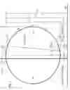
FIG. 1 is The Per Phase Impedance Circle for an Induction Machine used in the method claimed herein.
DESCRIPTION OF THE PREFERRED EMBODIMENTS
Disclosed herein is a method used to find values for the six impedances shown in FIG. 2 of IEEE Standard 112, while avoiding the blocked rotor test. FIG. 1 is the graphical equivalent of the model of IEEE 112.
The proposed method uses measurements taken on a fixed-frequency, freely-rotating machine operating at rated voltage and frequency. FIG. 1, while of help in understanding the general method and the equations used, is not to scale: D>>[X1+(X2∥XM)]>R1. Also, the point at (s=0) does not reflect the clockwise shift in slip due to the effect of Rfe. The validity of the method is justified by using ‘lab measurements’ generated by a computer analysis of the Class B machine whose six impedances and other characteristics are postulated below. Although per-phase power is used in the ‘Measurements’ and ‘Calculations’, it is assumed that the two wattmeter method (WA and WC) is used in the lab, and that the DC resistance, R1DC≈R1, has been measured and recorded.
Measurments and Calculations
Postulated Data for a Class B Machine
f=60 Hz; Vline=440 V; Vp=254 V; R1=0.50Ω; X1=X2=1.00Ω;
XM=39.0Ω; R2=0.640Ω; Rfe=320Ω; PWF=96.0 W; PRFE=192 W.
Measurements
- a) OP1: P1=931 W; I1=7.33 A; ROP1=17.3Ω; XOP1=30.0Ω;
- b) OP2: P2=2530 W; I2=12.1 A; ROP2=17.3Ω; XOP2=11.9Ω;
- c) s=0: P0=211 W
- d) No load: PNL=307 W; Inl=6.44 A: sNL=0.001;
Calculations
From d): RNL=PNL/(Inl)2=7.40Ω; ZNL=Vp/Inl=39.4Ω; 1)
XMAX=[(ZNL)2+(RNL−R1)2]0.5=40.0Ω;
From FIG. 1: Xc=(XOP1+XOP2)/2 =21.0Ω; 2)
D=2(XMAX−XC)=38.0Ω;
[X1+(X2∥X2)]≈(X1+X2)=(XMAX−D)=2.00Ω; for Class B,
(X1=X2)=(X1+X2)/2=1.00Ω; from FIG. 1,
XM=[(D+(X2∥X2)]=39.0Ω;
- 3) From c) and d):
PWF=[PNL−P0]=96 W; PRFE=[PNL−PWF(Inl2)(R1)]=190 W
Rfe=(Vrfe)2/PRFE; Vrfe=Vp(XM)/(XM+X1)=248 V; so Rfe=324Ω;
PWF=D(Inl)2(SNL/SN); so sN=D(Inl)2(sNL/PWF)=38.0(6.44)2(0.001/96.0)=0.0164; by definition: sN=R2/[XM+(X2)∥X2,)] so R2=sN[XM+(X2∥XM)]=0.0164(40)=0.656Ω. 4)
The correlation between the calculated impedance and per phase power values with those postulated above is good with the exception of R2, which is 2.5 percent high. A higher value of R2 may be fortuitous since the IEEE 112 model does not account for rotor and stray losses:
rn=sn/(1+sn)2 where sn=s/sN and s is per unit slip. For very small s,
rn≈sn and so PWF=(Inl)2(D)(sNL/sN); solving for sN:
sN≈[(Inl)2(D)(sNL)]/PWF=0.0164; by definition for the IEEE Standard model:
sN=[R2/(Xm+X2)]; so R2=sN(XM+X2)=0.656Ω.
The correlation between the calculated impedance values with those previously postulated from is good with the exception of R2, which is 3.44 percent high. A higher value of R2 may be fortuitous since the IEEE 112 model does not account for rotor core and stray losses. It is not necessary to select OP1 as shown although it is recommended. If OP1 is chosen with ROP1 too small (very light load), OP2 may overload the machine. If OP1 is too close to sN (see FIG. 1), XOP1 changes too rapidly for small changes in ROP1.
Claims
What is claimed is:1. A method for finding the numerical values of the rotational losses, the stator core loss and the impedances XM, X1, X2, RFE and R2 for a multiphase induction machine, the method comprising:
operating a freely-rotating induction machine at its rated voltage and rated fixed-frequency;
obtaining rotational losses, stator core loss and RFE from power readings at no load and synchronous speed;
using FIG. 1 to determine the values of XMAX, D and sX; and,
calculating the values of XM, X1, X2 and R2, where XM=(XMAX+D)/2, X1=[XMAX−XM], X2=[(XMAX−D)−X1] and R2=[sN(XMAX)].
Images & Drawings included:

Sources:
- United States Patent and Trademark Office - verify current appl. status at the USPTO↗
Recent applications in this class:
- » 20250004053 2025-01-02
ALTERNATOR MONITORING METHODS AND SYSTEMS - » 20240418779 2024-12-19
TEST SYSTEM - » 20240369634 2024-11-07
FAULT DETECTION IN SYNCHRONOUS MACHINES - » 20240353492 2024-10-24
LOAD TESTING DEVICE - » 20240345165 2024-10-17
FAULT DETECTION METHOD AND FAULT SYMPTOM DIAGNOSIS SYSTEM AND METHOD FOR SOLENOID ACTUATORS - » 20240210474 2024-06-27
System and Method for Obtaining an Estimated Output Power of an Electric Motor - » 20240201262 2024-06-20
SYSTEM AND METHOD FOR INDUCTION MOTOR INTRA-CORE ROTOR BAR SURFACE MAGNETIC FIELD ANALYSIS - » 20240085481 2024-03-14
METHOD AND APPARATUS FOR BRUSHLESS ELECTRICAL MACHINE CONTROL - » 20240085480 2024-03-14
INSPECTION DEVICE FOR ROTARY ELECTRIC MACHINE, INSPECTION SYSTEM FOR ROTARY ELECTRIC MACHINE, INSPECTION METHOD FOR ROTARY ELECTRIC MACHINE, AND ROTARY ELECTRIC MACHINE TO BE INSPECTED USING INSPECTION DEVICE - » 20240044984 2024-02-08
REMAINING LIFE DETERMINING SYSTEM FOR MOTOR