UV lasers and UV Raman systems for effective and efficient molecular species identification with Raman spectroscopy
US20190109431A1
2019-04-11
16/153,261
2018-10-05
✅ Patent granted
US 10,965,091 B2
2021-03-30
-
-
Xinning (Tom) Niu
McKee, Voorhees & Sease, PLC
2038-10-05
Abstract:
The present invention relates to a novel stand-off distance chemical detector system such as can be used, for example, for standoff detection of explosives. Instead of a conventional lasing medium, a Pr:YAG or Pr:BYF based UV laser is used which can be advantageously implemented in Raman spectroscopy.
Inventors:
- Ed Dottery 4 🇺🇸 Palm Harbor, FL, United States
- Darius Vunck 3 🇺🇸 Clearwater, FL, United States
- David Welford 12 🇺🇸 Danvers, MA, United States
- Robert Dean Babnick 3 🇺🇸 Largo, FL, United States
- Robert Douglas Waterbury 3 🇺🇸 Palm Harbor, FL, United States
- Timothy Molner 2 🇺🇸 St. Petersburg, FL, United States
- Hunter Hardy 1 🇺🇸 Pinellas Park, FL, United States
- Robert McKinney 1 🇺🇸 Winter Park, FL, United States
Assignee:
- Alakai Defense Systems, Inc. 9 🇺🇸 Largo, FL, United States
Applicant:
Interested in similar patents?
Get notified when new applications in this technology area are published.
Classification:
G01J3/10 » CPC further
Spectrometry; Spectrophotometry; Monochromators; Measuring colours; Details Arrangements of light sources specially adapted for spectrometry or colorimetry
H01S3/16 IPC
Lasers, i.e. devices using stimulated emission of electromagnetic radiation in the infrared, visible or ultraviolet wave range characterised by the material used as the active medium Solid materials
G01J3/021 » CPC further
Spectrometry; Spectrophotometry; Monochromators; Measuring colours; Details; Optical elements not provided otherwise, e.g. optical manifolds, diffusers, windows using plane or convex mirrors, parallel phase plates, or particular reflectors
G01J3/0208 » CPC further
Spectrometry; Spectrophotometry; Monochromators; Measuring colours; Details; Optical elements not provided otherwise, e.g. optical manifolds, diffusers, windows using focussing or collimating elements, e.g. lenses or mirrors; performing aberration correction
G01J3/0248 » CPC further
Spectrometry; Spectrophotometry; Monochromators; Measuring colours; Details; Optical elements not provided otherwise, e.g. optical manifolds, diffusers, windows using a sighting port, e.g. camera or human eye
G01J3/0272 » CPC further
Spectrometry; Spectrophotometry; Monochromators; Measuring colours; Details Handheld
H01S3/08059 » CPC further
Lasers, i.e. devices using stimulated emission of electromagnetic radiation in the infrared, visible or ultraviolet wave range; Construction or shape of optical resonators; Accommodation of active medium therein; Shape of active medium; Construction or shape of optical resonators or components thereof Constructional details of the reflector, e.g. shape
H01S3/094084 » CPC further
Lasers, i.e. devices using stimulated emission of electromagnetic radiation in the infrared, visible or ultraviolet wave range; Processes or apparatus for excitation, e.g. pumping using optical pumping by coherent light with pump light recycling, i.e. with reinjection of the unused pump light, e.g. by reflectors or circulators
H01S3/1643 » CPC further
Lasers, i.e. devices using stimulated emission of electromagnetic radiation in the infrared, visible or ultraviolet wave range characterised by the material used as the active medium; Solid materials characterised by a crystal matrix garnet YAG
H01S3/0405 » CPC further
Lasers, i.e. devices using stimulated emission of electromagnetic radiation in the infrared, visible or ultraviolet wave range; Constructional details; Arrangements for thermal management Conductive cooling, e.g. by heat sinks or thermo-electric elements
H01S3/0815 » CPC further
Lasers, i.e. devices using stimulated emission of electromagnetic radiation in the infrared, visible or ultraviolet wave range; Construction or shape of optical resonators; Accommodation of active medium therein; Shape of active medium; Construction or shape of optical resonators or components thereof comprising more than two reflectors; Configuration of resonator having 3 reflectors, e.g. V-shaped resonators
H01S3/08054 » CPC further
Lasers, i.e. devices using stimulated emission of electromagnetic radiation in the infrared, visible or ultraviolet wave range; Construction or shape of optical resonators; Accommodation of active medium therein; Shape of active medium; Construction or shape of optical resonators or components thereof Passive cavity elements acting on the polarization, e.g. a polarizer for branching or walk-off compensation
H01S3/09415 » CPC further
Lasers, i.e. devices using stimulated emission of electromagnetic radiation in the infrared, visible or ultraviolet wave range; Processes or apparatus for excitation, e.g. pumping using optical pumping by coherent light of a laser diode the pumping beam being parallel to the lasing mode of the pumped medium, e.g. end-pumping
H01S3/1646 » CPC further
Lasers, i.e. devices using stimulated emission of electromagnetic radiation in the infrared, visible or ultraviolet wave range characterised by the material used as the active medium; Solid materials characterised by a crystal matrix halide BaYF
H01S3/1653 » CPC further
Lasers, i.e. devices using stimulated emission of electromagnetic radiation in the infrared, visible or ultraviolet wave range characterised by the material used as the active medium; Solid materials characterised by a crystal matrix halide YLiF(YLF, LYF)
H01S5/32341 » CPC further
Semiconductor lasers; Structure or shape of the active region; Materials used for the active region comprising PN junctions, e.g. hetero- or double- heterostructures in AB compounds, e.g. AlGaAs-laser, InP-based laser emitting light at a wavelength less than 900 nm blue laser based on GaN or GaP
H01S3/109 » CPC main
Lasers, i.e. devices using stimulated emission of electromagnetic radiation in the infrared, visible or ultraviolet wave range; Controlling the intensity, frequency, phase, polarisation or direction of the emitted radiation, e.g. switching, gating, modulating or demodulating by controlling a device placed within the cavity using a non-linear optical device, e.g. exhibiting Brillouin- or Raman-scattering Frequency multiplying, e.g. harmonic generation
H01S3/0941 » CPC further
Lasers, i.e. devices using stimulated emission of electromagnetic radiation in the infrared, visible or ultraviolet wave range; Processes or apparatus for excitation, e.g. pumping using optical pumping by coherent light of a laser diode
G01J3/44 » CPC further
Spectrometry; Spectrophotometry; Monochromators; Measuring colours; Investigating the spectrum Raman spectrometry; Scattering spectrometry ; Fluorescence spectrometry
H01S3/08 IPC
Lasers, i.e. devices using stimulated emission of electromagnetic radiation in the infrared, visible or ultraviolet wave range; Construction or shape of optical resonators; Accommodation of active medium therein; Shape of active medium Construction or shape of optical resonators or components thereof
G01J3/02 IPC
Spectrometry; Spectrophotometry; Monochromators; Measuring colours Details
H01S3/094 IPC
Lasers, i.e. devices using stimulated emission of electromagnetic radiation in the infrared, visible or ultraviolet wave range; Processes or apparatus for excitation, e.g. pumping using optical pumping by coherent light
H01S3/042 » CPC further
Lasers, i.e. devices using stimulated emission of electromagnetic radiation in the infrared, visible or ultraviolet wave range; Constructional details; Arrangements for thermal management for solid state lasers
H01S3/04 IPC
Lasers, i.e. devices using stimulated emission of electromagnetic radiation in the infrared, visible or ultraviolet wave range; Constructional details Arrangements for thermal management
H01S5/323 IPC
Semiconductor lasers; Structure or shape of the active region; Materials used for the active region comprising PN junctions, e.g. hetero- or double- heterostructures in AB compounds, e.g. AlGaAs-laser, InP-based laser
H01S3/1613 » CPC further
Lasers, i.e. devices using stimulated emission of electromagnetic radiation in the infrared, visible or ultraviolet wave range characterised by the material used as the active medium; Solid materials characterised by an active (lasing) ion rare earth praseodymium
H01S3/081 IPC
Lasers, i.e. devices using stimulated emission of electromagnetic radiation in the infrared, visible or ultraviolet wave range; Construction or shape of optical resonators; Accommodation of active medium therein; Shape of active medium; Construction or shape of optical resonators or components thereof comprising more than two reflectors
Description
CROSS-REFERENCE TO RELATED APPLICATIONS
This application claims the benefit of Provisional Application U.S. Ser. No. 62/568,892 filed on Oct. 6, 2017, all of which is herein incorporated by reference in its entirety.
I. BACKGROUND OF THE INVENTION
A. Field of the Invention
The present invention relates to methods and systems relating to the design of new UV laser/UV Raman system combinations.
B. Problems in the State of the Art
1. Background
a. UV Laser—Pr:YAG@244 nm and Praseodymium YAG Solid State Material Characteristics
A recently developed laser concept incorporates Praseodymium (“Pr”) as the active laser ion which can be doped into a number of crystal host materials. The Praseodymium laser is one of the very few laser sources which is capable of directly producing outputs in the visible wavelength spectrum. Initially this material was investigated with great interest for the production of three color laser displays. However, subsequent rapid development of high power direct laser diodes in the visible spectrum reduced the need for such solid state lasers. Thus, much of the active research declined.
More recent developments in low cost, high power blue laser diode pump sources and the need for UV laser sources has brought renewed attention to Praseodymium doped lasers.
The Praseodymium ion has a complex energy structure within the host crystal. Multiple energy transitions are possible which are capable of producing various visible wavelengths from the deep blue to the dark red with green and yellow lines between. Most efforts at producing UV through intra-cavity frequency doubling have employed the green 522 nm fundamental transition which results in a UV wavelength of 261 nm. In this configuration, the host crystal is VLF (very low frequency) instead of YAG. The 261 nm wavelength is not ideal for certain applications involving spectroscopic identification of molecular species. A shorter wavelength produces a better signal condition. The unique property of Praseodymium:YAG which makes it a very interesting candidate for a shorter wavelength UV laser source is a clear difference between the pump wavelength absorption line at 445 nm and the laser emission line at 488 nm. Most materials exhibit a strong overlap in these two bands which means that it is difficult or impossible to develop any laser gain due to self-absorption. By optimizing the fundamental 488 nm laser wavelength and then introducing a single frequency doubling crystal intra-cavity, a wavelength of 244 nm should be possible. Recent measurements have shown a strong laser cross section of 24.4×10⁻²⁰ cm2 for the 488 nm transition. This is of similar magnitude to the measured cross sections from other host materials which produce strong laser outputs at longer wavelengths.
b. UV Laser—Pr:BYF@247.5 nm and Praseodymium BYF Solid State Material Characteristics
The first demonstration of a directly-pumped blue laser using a Pr3+-doped medium took place in 1977 at the Naval Research Laboratory under the direction of Leon Esterowitz and co-workers └Est77┘, who demonstrated room temperature lasing of Pr:YLF at 479 nm when pumped with a 444-nm pulsed dye laser.
Recent advances in GaN diode lasers operating in the 440-nm to 450-nm range have been used to efficiently pump Pr3+-doped fluorides (e.g. YLF was the most common) operating in the visible [Cor08, Met13,Rei12b, Str10]. To our knowledge, the only use of Pr with Barium Yttrium Fluoride (BYF) is from [Met13, Met13a] which demonstrated lasing at 495 nm using a 445-nm GaN pump diode.
While other Pr based lasers have been frequency doubled, none have been frequency doubled and resulted in a wavelength which is <250 nm. The wavelength of <250 nm is important in for Deep Ultra Violet (DUV) Raman because it results in fluorescence free Raman spectroscopy. While the Pr:YAG & Pr:BYF lasers both operate below 250 nm, the Pr:BYF is more efficient (requires less input electrical power to produce the same output power) and has several other advantages.
2. Problem Statement
As indicated above, systems and techniques of this type present a number of competing interests and factors. The properties of materials, their reaction to light energy, and even their cost and complexity to implement effectively in such applications as spectroscopy-based detection systems having an interrogation beam and reflectance collection of scattering from the beam relative the target, are but a few that both (a) produce efficient and effective laser sources, especially in molecular species identification using spectroscopy and, further, especially in Raman spectroscopy and (b) produce better signals for molecular species analysis especially in Raman spectroscopy which has challenges regarding separating relevant signal from irrelevant. This does not typically allow for predictable substitutions. Therefore, there is room for improvement in this technical state of the art.
II. SUMMARY OF THE INVENTION
A. Objects, Features, and Advantages of the Solution of the Invention
A principal object of the present invention is to provide apparatus, systems, and methods for solving problems or overcoming deficiencies in the state-of-the-art regarding optical detectors.
As will be seen by reference to the following disclosure, the solutions of the present invention provide one or more of the following benefits:
-
- a. generation of UV laser frequencies effectively, economically, and efficiently, including for interrogation sources for spectrometers;
- b. opportunities for advantageous form factors and reduced size portable instruments using such laser generation techniques;
- c. a shorter wavelength initial laser source which can then be frequency doubled to UV wavelength for Raman spectrometry;
- d. effective generation of UV interrogation laser for better fluorescence rejection;
- e. ability to have greatly reduced background fluorescence because the laser wavelength is <250 nm;
- f. combines generation of efficient and effective Pr-based laser designs with efficient and effective molecular species identification for improved systems, methods, and apparatus over the state of the art.
These and other advantages, options, and features meaningful to the invention are disclosed herein and will become more apparent with reference to the accompanying description, drawings, and claims.
B. Aspects of the Solution of the Invention
As can be appreciated by the foregoing, the competing interests and unpredictability of combination of elements in this technical area presents challenges. The inventors have innovated by combining certain elements in an efffacious manner, particularly by the insight of use of Pr:YAG and Pr:BYF lasers.
-
- Below are the laser designer challenges and/or unique technical issues the invention addresses to get the Pr:YAG to work:
- a. Pump geometry—End Pumped—The simplest design is to use end pumped configuration. While this will work, the design will be limited in the amount of output power that can be produced and Amplified Spontaneous Emission (ASE). Since this is a CW laser, the ASE can be managed by coating design which efficiently reflects the desired 488 and 244 nm wavelengths and attenuates the other wavelengths.
- b. Pump geometry—Side Pumped—Utilizing this configuration allows a more powerful laser since (1) more pump laser diodes can be coupled to the Pr:YAG crystal and (2) the resonator design will allow for a double pass through the intra-cavity doubling crystal (BBO) thereby improving its efficiency.
- c. Laser Self Absorption—One of the challenges with the Pr:YAG laser is that the pump wavelength and lasing wavelength are fairly close (445 and 488 nm). This means that all components of the laser design need to ensure that the 488 nm wavelength propagates efficiently in the resonator (and 244 nm since this is an intra-cavity doubled design) and that the other wavelengths are attenuated within the resonator. This means that the anti-reflection (AR) coatings of the crystal and the reflectivity of the mirrors must be designed appropriately.
- i. The absorption within the Pr:YAG crystal is polarization dependent, thus the crystal orientation and coatings design will be designed to operate at the polarization state which has the largest wavelength separation between the pump (445 nm) and lasing (488 nm).
- d. UV only operation—Since the Pr:YAG can lase at multiple wavelengths other than the desired 488 nm line, the mirror coatings must be non-reflective at all other wavelengths.
- Below are the laser designer challenges and/or unique technical issues the invention addresses to get the Pr:YAG to work:
At least similar challenges and solutions exist relative to use of Pr:BYF based-lasers, as further discussed herein.
III. BRIEF DESCRIPTION OF THE DRAWINGS
The patent or application file contains at least one drawing executed in color. Copies of this patent or patent application publication with color drawing(s) will be provided by the Office upon request and payment of the necessary fee.
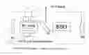
FIG. 1. Pr:YAG Laser design—Concave-convex resonator—according to one exemplary embodiment of the invention.
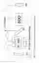
FIG. 2. Pr:YAG laser design—Cross-Porro Prism Resonator concept—according to another exemplary embodiment of the invention.
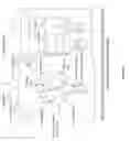
FIG. 3. Double Pass Circular Sapphire Clamp Heat Sink Resonator concept for Pr:YAG laser from Existing Literature.
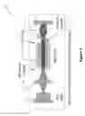
FIG. 4. Embodiment of a portable UV Raman system utilizing a 244 nm Pr:YAG laser such as FIGS. 1 and 2 according to an exemplary embodiment of the invention. Size of system in this example is on the order of 8 inches×8 inches×3 inches.
FIG. 5. An alternative embodiment similar to that of FIG. 1, but using an end-pumped laser.
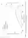
FIG. 6: A graph related to a further embodiment according to aspects of the invention related to use of a Pr:BYF laser.
FIG. 7: Another graph related to a Pr:BYF laser embodiment.
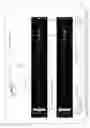
FIG. 8: A graphic illustration of operation of a Pr:BYF embodiment.
FIG. 9: A further graphic illustration of operation of a Pr.BYF embodiment.
FIG. 10: A further graphic illustration of operation of a Pr.BYF embodiment.
IV. DETAILED DESCRIPTION OF EXEMPLARY EMBODIMENTS OF THE INVENTION
A. Overview
For a better understanding of the invention, some examples of forms it can take all now be described in detail. It is to be understood these are neither exclusive nor inclusive of all such forms or embodiments the invention can take.
First, several embodiments and options useable with a Raman or LIDOR sensor for chemical detection at standoff distances will be described. Variations obvious to the skill you will be included within these embodiments.
Second, an expansion of those concepts to optional features or alternatives will be described. It will be understood by those skilled in the art that these are examples only for illustration and variations obvious to those skilled in the art of course possible.
It will also be understood that the examples focus, just for purposes of simplicity, on detection of explosives such as used with IEDs (improvised explosive devices). The concept of the invention can be applied to a wide variety of chemicals, chemical compounds, and chemical constituents, as is well known in Raman- or LIDOR-based spectroscopy. Form factor and characteristics of the components, as well as the parameters to control them, will, of course, also vary according to need or desire.
B. UV Generation Using Intra-Cavity Frequency Doubling
This aspect of the present invention is now described with reference to FIGS. 1 and 2. FIGS. 1 and 2 present non-limiting examples of optimizing the fundamental (e.g. 488 nm) laser wavelength and then introducing a single frequency doubling crystal intra-cavity (e.g. making a wavelength of 244 nm possible).
System 10 of FIG. 1 operates as follows.
Strong continuous output UV at a wavelength of 244 nm should be possible by the introduction of a second harmonic non-linear crystal 12 into the resonator 11 previously optimized for the 488 nm oscillation. The non-linear crystal of choice for this wavelength range and for continuous operation is BBO. BBO is widely used for second harmonic generation to the UV both extra-cavity and intra-cavity. BBO is a well-known crystal and is available from many sources. BBO crystal has both high transmission and is impervious to color center formation by the UV energy. BBO crystal also has a high damage threshold, good thermal properties for high average power operation.
Laser generation with pumping laser diodes and frequency multipliers is well-known. Further details for background can be found at least at US 20130293882 A1 (stand off distance Raman detection and an example of a standoff distance Raman-based spectrometer for chemical detection); U.S. Pat. No. 6,327,281 (BBO-based frequency multiplier resonator and an example of a BBO based laser resonator); U.S. Pat. No. 8,125,627 (a different UV laser and an example of IR visible UV lasers), each of the foregoing incorporated by reference herein in its entirety.
C. Resonator Concepts and Description Regarding Pr:YAG Laser
The arrangement within the cavity 11 is as shown in FIG. 1. A polarizer P1 is introduced into the cavity to assure a highly polarized beam in the frequency doubling leg. The polarizer P1 serves the dual purpose of polarizing the circulating fundamental wavelength and also as the output coupling means for the UV (see “UV Output 19”). This arrangement 11 allows a second pass through the 880 crystal to optimize the UV generation. After the second pass through the 880 crystal 12, the UV component is reflected by the plate polarizer P1 and becomes the “UV output” beam 19 from the resonator 11. The remainder of the 488 nm fundamental passes through the polarizer P1 and returns to the Pr:YAG crystal 20.
The resonator may be terminated with conventional mirrors M1 and M2 with dielectric coatings. The resonator 11 geometry will employ a concave-convex resonator design which will maximize the mode volume and therefore the circulating power of the oscillating fundamental wavelength. This resonator geometry is very stable over environmental changes in temperature and slight structural misalignments.
As is well-known to those skilled in this technical area, the resonator 11 of FIG. 1 is basically an an arrangement of mirrors that forms a standing wave cavity resonator for light waves. Optical cavities are a major component of lasers, surrounding the gain medium and providing feedback of the laser light. Details regarding the basic optical resonator configuration and operation can be found at U.S. Pat. No. 6,327,281, which is incorporated by reference herein. Its end mirrors M1 and M2, housing, and other conventional components are commercially available. Here M1 is concave and M2 convex at facing, functional surfaces.
In this embodiment, the laser 14 comprises a Pr:YAG laser with four pump diodes 15 at 445 nm each. This produces the 488 visible light oscillation from this lasing medium.
BBO 16 is a specific optical-grade crystal and commercially available. One example is at U.S. Pat. No. 6,327,281 which is incorporated by reference herein.
Polarizer P1 is commercially available and functions as explained above.
The above combination can be configured to produce a desired UV output 19 as discussed above. The beneficial aspects are as outlined above.
1. Alternate Designs:
One non-limiting alternative to FIG. 1 is diagrammatically illustrated at FIG. 2. A Pr:YAG laser source, its pump diodes, and the BBO crystal can be similar to 20, 22, and 12 of FIG. 1. The main differences are highlighted below.
1. Cross-Porro Design 30: This design 30 employs retro-reflecting porro prisms and the end elements 24 and 26 (FIG. 2). Porro prisms oriented with crossed roof lines are a very stable optical configuration. Arrangement 30 produces a similar result as system 10 of FIG. 1 but with this different set-up. The fundamental concepts of cross-porro arrangements can be seen at U.S. Pat. No. 5,199,042 (an example of a cross-porro prism resonator), incorporated by reference herein.
2. Double Pass Axial Configuration 40: This design 40 employs 6 pump diodes 22 (instead of four in FIGS. 1 and 2) arranged using a sapphire circular clamp heatsink 32 as shown in FIG. 3. This design results in a double pass configuration for high power. In addition, the sapphire circular clamp heatsinks 32 results in the ability to keep the Pr:YAG rod 20 at lower temperatures thereby improving performance at the higher output powers.
As shown in FIG. 3, this embodiment uses a different resonator cavity (double pass) using semi-cylinder sapphire shapes. One example of a sapphire heat sink resonator is at U.S. Pat. No. 5,317,585 (an example of a sapphire-based heat sink used in a laser resonator), incorporated by reference herein. The lasing medium however is Pr:YAG. FIG. 3 shows one way to set up resonance in the cavity, including mirrored sectors 36A-C and each associated diode pump 22A-C) including cylinder lenses 23A-C) (diagrammatic depiction of two-way reflection between just one pump 22B and one mirrored sector 36B is shown for simplicity). Frequency doubling is achieved by intracavity doubling using a BBO Harmonic Conversion crystal (as previously described).
3. Simple Co-Linear Design: This design 10′ (FIG. 5) employs an end pumped (diode(s) 22) resonator 11′ with an intra-cavity doubling crystal 12 all resulting in a co-linear design. This design will have less output power then the other designs but may be sufficient for some applications. See FIG. 5. See, e.g., U.S. Pat. No. 5,446,749, an example of a doubling crystal and end pumped resonator and incorporated by reference herein.
To our knowledge nobody has fabricated a Pr:YAG laser in this manner despite the following :
There is a published article on the material properties of the Pr: YAG crystal:
-
- Wenpeng Liu & Qingli Zhang (2017) Growth and spectral properties of Pr3+-doped Y3Al5O12 crystal for potential use in all-solid state visible laser, Materials Research Innovations, 21:2, 65-68, DOI: 10.1080/14328917.2016. 1 183334; an example of growth and spectral properties of Pr3+-doped Y3Al5O12 crystal for potential use in all-solid state visible laser, and incorporated by reference herein.
There is published info on PR: YLF lasers:
-
- Vasiliy Ostroumov, Wolf Seelert, Lukas Hunziker, Chris Ihli, “522/261 nm cw generation of Pr:YLF laser pumped by OPS laser'\ Proc. SPIE 6451, Solid State Lasers XVI: Technology and Devices, 645104 (8 Feb. 2007), an example of a 522/261 nm cw generation of Pr:YLF laser pumped by OPS laser, and incorporated by reference herein.
- psi.fuw.edu.pl/pub/lPWb/Lasery/ALKAAD_PrYLF_Laser.pdf, another example and incorporated by reference herein.
There is published patent literature on a Pr-doped optical fiber, and an example of a discussion of a Praseodymium laser, see e.g., U.S. Pat. No. 5,309,452 incorporated by reference herein.
2. UV Raman Systems
Another aspect of the invention is illustrated at FIG. 4.
Most UV Raman systems are rather. Large (>1 cu ft) (see CPEDS™ and PRIED™ systems (available commercially from Alakai Defense Systems, Inc., Largo, Fla. (USA) with product descriptions at https://docs.wixstatic.com/ugd/3e1446_cf8257f776944296b3dbe6f6302e260e.pdf and https://docs.wixstatic.com/ugd/3e1446_b9e1071632114fb3b23bdc0ccb9546a1.pdf respectively, and see also US 20130293882 A1 for details; all incorporated by reference herein). Most small portable Raman systems utilize non-UV wavelength lasers (typically 532, 785 nm or 1064 nm).
FIG. 4 show a first embodiment according to aspects of the invention of a 245 nm laser (e.g. as discussed above) into a handheld UV Raman system 100. In this system 100, the transmitted light is generated by the 244 Pr:YAG laser 50. Its output is folded to be collinear with the collection beam (collected by collection optics 102) by the edge filter 107 (See U.S. Pat. No. 7,123,416, for an example of edge filters and incorporated by reference herein). The transmit beam is then sent out of the system 100 and the operator points it at the desired target (at stand off distance, not shown). The range finder 108 determines the range to the target and then adjust the focus of the main collection optics 102. The return beam is collected by the collection optics 102. The edge filter 107 then sends only the Raman shift light to the spectrometer 104. The processor 106 (via PCB 105) reads the output and then utilizing a proprietary algorithm determines the chemical that are present at the sample (at the target). The results are communicated to the main interface device (not shown and could be remote and/or wireless) (e.g. an Android or iPhone not shown). This embodiment can beneficially be packages in relatively small, more portable form factor and weight than typical UV Raman systems, yet its unique combination achieves at least one or more of the objects, features, or advantages described herein, including but not limited to an efficient and effective technique to generate the proper interrogation lasers to promote improved signal for molecular species identification, including with Raman spectroscopy.
Alternative embodiments (non-limiting) could include:
-
- 1. the collection optics can use either:
- a. a collinear design as shown in FIG. 4; or
- b. a non-collinear design using off-axis spherical or aspherical optics.
- 2. the range finder could be any of the following:
- a. a standard time-of-flight laser range finder;
- b. utilize a linear array in a laser triangulation implementation;
- c. an auto-focus range estimator;
- d. other.
- 3. the angles between the transmit axis and the receive axis could be:
- a. roughly perpendicular as shown;
- b. roughly parallel.
- 4. the coupling between the collection optics and spectrometer could be:
- a. direct optical couples as shown;
- b. utilize an optical fiber which could be a single fiber or a multi-element fiber array.
- 5. the user interface could take a variety of configurations.
- 1. the collection optics can use either:
D. UV Laser—Pr:BYF@247.5 nm
Another aspect of the invention utilizes a Pr:BYF-based UV laser (see reference number 20′ in FIGS. 8-10). It can be implemented in similar operational configurations as discussed above regarding systems using a Pr:YAG-based laser (reference number 20 in FIGS. 1-5), so reference can be also be taken to FIGS. 1-5 and the foregoing description regarding such details. However, with reference to FIGS. 6-10, aspects of Pr:BYF-based UV lasers and use in UV Raman systems are discussed below.
1. Praseodymium BYF Solid State Material Characteristics
The first demonstration of a directly-pumped blue laser using a Pr3+-doped medium took place in 1977 at the Naval Research Laboratory under the direction of Leon Esterowitz and co-workers ┌Est77 at list of References infra┐, who demonstrated room temperature lasing of Pr:YLF at 479 nm when pumped with a 444-nm pulsed dye laser. Recent advances in GaN diode lasers operating in the 440-nm to 450-nm range have been used to efficiently pump Pr3+-doped fluorides (e.g. YLF was the most common) operating in the visible [Cor08, Met13,Rei12b, Str10]. To our knowledge, the only use of Pr with Barium Yttrium Fluoride (BYF) is from [Met13, Met13a] which demonstrated lasing at 495 nm using a 445-nm GaN pump diode.
While other Pr based lasers have been frequency doubled, none have been frequency doubled and resulted in a wavelength which is <250 nm. The wavelength of <250 nm is important in for Deep Ultra Violet (DUV) Raman because it results in fluorescence free Raman spectroscopy. While the Pr:YAG & Pr:BYF lasers both operate below 250 nm, the Pr:BYF is more efficient (requires less input electrical power to produce the same output power) and has several other advantages.
2. UV Generation Using Intra-Cavity Frequency Doubling
Strong continuous output UV at a wavelength of 247.5 nm should be possible by the introduction of a second harmonic non-linear crystal into the resonator previously optimized for the 495 nm oscillation. The non-linear crystal of choice for this wavelength range and for continuous operation is BBO. BBO is widely used for second harmonic generation to the UV both extra-cavity and intra-cavity. BBO is a well-known crystal and is available from many sources. BBO has both high transmission and is impervious to color center formation by the UV energy. BBO also has a high damage threshold, good thermal properties for high average power operation. FIGS. 6 and 7 show the results of LASCAD modeling which indicate sufficient laser output power (−100 mW) of the Second harmonic (SH) laser beam which is at 247.5 nm.
3. Resonator Concepts and Description
Two arrangements of a simple resonator cavity are shown in FIGS. 8 and 9. Both of these designs utilize a single pumping laser diode. The configuration of FIG. 8 utilizes a folded resonator design which will be easier to align since it is a little larger package. FIG. 9 shows a linear design which results in a physically smaller more compact laser but may be more problematic to align. In both cases of these examples of a Pr:BYF-based system, there are two Second Harmonic (SH) beam generated (247.5 nm). If sufficient power is achieved with one beam then the second beam can be ignored. However if more power is required, then this second beam can be combined with the original beam with classical lenses and mirrors to form a single beam.
The resonator may be terminated with conventional mirrors with dielectric coatings. The resonator geometry will employ a concave-concave resonator design which will maximize the mode volume and therefore the circulating power of the oscillating fundamental wavelength. This resonator geometry is very stable over environmental changes in temperature and slight structural misalignments.
Alternate resonator designs:
-
- 1. Two pump sources: FIG. 10 shows a resonator design which supports two pump diodes in case additional power is required.
The following concepts refer to figures which show a Pr:YAG crystal however the concepts will work for Pr:BYF also:
-
- 2. Cross-Porro Design: This design employs retro-reflecting porro prisms and the end elements (see, e.g., FIG. 2). Porro prisms oriented with crossed roof lines are a very stable optical configuration.
- 3. Double Pass Axial Configuration: This design employs six pump diodes arranged using a sapphire circular clamp heatsink as shown in FIG. 3. This design results in a double pass configuration for high power. In addition the sapphire circular clamp heatsinks results in the ability to keep the Pr:BYF rod at lower temperatures thereby improving performance at the higher output powers.
REFERENCES (EACH INCORPORATED BY REFERENCE HEREIN)
- [Cor08] F. Cornacchia, A Di Lieto, M. Tonelli, A. Richter, E. Heumann, and G. Huber, “Efficient visible laser emission of GaN laser diode pumped Pr-doped fluoride scheelite crystals,” Opt. Express, 16, (2008), 15932.
- [Met13] P. Metz, D. Parisi, K. Hasse, N. Hansen, C. Kränkel, M. Tonelli, and G. Huber, “Room temperature cyan Pr3+:BaY2F8 laser at 495 nm,” in Advanced Solid-State Lasers Congress, G. Huber and P. Moulton, eds., OSA Technical Digest (online) (Optical Society of America, 2013), paper AF2A.
- [Met13a] P. Metz, K. Hasse, D. Parisi, N. O. Hansen, C. Kränkel, M. Tonelli, and G. Huber, “Continuous-wave Pr3+:BaY2F8 and Pr3+:LiYF4 lasers in the cyan-blue spectral region,” Optics lets., 39, 5158, (2013).
- [Rie14] R. Riedal et al., “Thermal properties of borate crystals for high power optical parametric chirped-pulse amplification,” Opt. Express, 22, 17607, (2014).
- [Str10] M. Strotkamp, T. Schwarz, B. Jungbluth, H. Faidel, and M. Leers, “Efficient, green laser based on a blue-diode pumped rare-earth-doped fluoride crystal in an extremely short resonator,” Proc. SPIE., 7578, (2010), 7578-24.
E. Options and Alternatives
As will be appreciated by those having skill in this technical art, options and alternatives to the foregoing exemplary embodiments are of course possible. Variations obvious to those skill to be included within the invention which is not limited by the embodiments disclosed herein. Some additional examples of options and alternatives are as follows.
1. Form Factor
As indicated above, the form factor of each of the components can vary according to need or desire. Portability can be approximately less than a fraction of a meter in all dimensions for housing 101 in FIG. 4.
2. Control System
Components necessary to allow inter-communication between electrical/electronic functions of the system can be selected and configured in a variety of ways according to the designer's needs and desires. This could include some type of programmable processor or controller.
3. Adjustability
Both factory settings and subsequent adjustments of operation of the system can be easily accomplished by programming and programming of a microprocessor or other intelligent control, including any number of factors, parameters, and the like according to the designer's need or desire. Such programming is well-known.
Claims
What is claimed is:1. A solid state laser for generating a UV laser for a UV Raman detector comprising:
a. a resonator cavity having a main intra-cavity optical path;
b. a pumped Pr:YAG or Pr:BYF lasing medium along the main intra-cavity optical path configured to generate a laser with an emission line resonating in the visible light spectrum;
c. a frequency doubling crystal along the main intra-cavity optical path configured to convert the visible light oscillation to UV oscillation at <250 nm;
d. an optical component along the main intra-cavity optical path configured to direct the UV oscillation out of the cavity for extra-cavity UV laser output for use in a Raman spectrometry detection scheme.
2. The solid state laser of claim 1 wherein:
a. the pumped lasing medium comprises:
i. a Pr:YAG lasing medium;
ii. at least one pump laser diode;
iii. adapted to create a visible light oscillation; and
b. the doubling crystal comprises a BBO harmonic conversion crystal adapted to covert the visible light oscillation to UV oscillation.
3. The solid state laser of claim 2 wherein the solid state laser is pumped with plural pumping laser diode and:
a. the visible light oscillation is at 488 nm;
b. the UV oscillation is at 244 nm.
4. The solid state laser of claim 3 wherein the at least one laser pump diode are in one of:
a. an end-pumped axial arrangement; or
b. a transaxial arrangement.
5. The solid state laser of claim 1 wherein the resonator cavity comprises a concave-convex resonator.
6. The solid state laser of claim 1 wherein the resonator cavity comprises a cross-porro prism resonator.
7. The solid state laser of claim 1 wherein the resonator cavity comprises a double-pass axial concentrator resonator.
8. The solid state laser of claim 7 wherein the double-pass axial concentrator resonator comprises a conductive sapphire heat sink.
9. The solid state laser of claim 1 wherein the optical component for the output laser comprises a dichroic filter.
10. The solid state laser of claim 9 wherein the dichroic filter further comprises a polarizer.
11. The solid state laser of claim 1 further comprising a component which reflects relevant wavelengths of light and attenuates irrelevant wavelengths, wherein the component comprises at least one of:
a. an optical coating;
b. ASE; and
c. AR coating.
12. The solid state laser of claim 1 in combination with a UV Raman system comprising:
a. a hand-held housing;
b. an on-board power source;
c. a processor and circuit;
d. collection optics;
e. spectrometer; and
f range finder.
13. The solid state laser of claim 1 wherein:
a. the pumped lasing medium comprises:
i. a Pr:BYF lasing medium;
ii. at least one pumping laser diode;
iii. adapted to create a visible light oscillation; and
b. the doubling crystal comprises a BBO harmonic conversion crystal adapted to covert the visible light oscillation to UV oscillation.
14. The solid state laser of claim 13 wherein the solid state laser is with the at least one pumping laser diode and:
a. the visible light oscillation is at 495 nm;
b. the UV oscillation is at 247.5 nm.
15. The solid state laser of claim 14 wherein the at least one pumping laser diode comprises:
a. one pumping laser diode;
b. more than one pumping laser diode.
16. The solid state laser of claim 13 wherein the resonator comprises a folded resonator design with two pump lasers diodes.
17. The solid state laser of claim 13 wherein the resonator comprises a linear resonator design.
18. The solid state laser of claim 13 wherein the resonator cavity comprises a cross-porro prism resonator.
19. The solid state laser of claim 13 wherein the resonator cavity comprises a double-pass axial concentrator resonator.
20. The solid state laser of claim 13 in combination with a UV Raman system comprising:
a. a hand-held housing;
b. an on-board power source;
c. a processor and circuit;
d. collection optics;
e. spectrometer; and
f. range finder.
21. A method of creating a UV laser for use in a Raman-based spectroscopy detection comprising:
a. generating a UV laser by:
i. generating an optimized oscillation in the visible spectrum using pumped Pr:YAG or Pr:BYF as the lasing medium;
ii. frequency doubling the optimized oscillation into the UV spectrum at <250 nm;
b. using the UV oscillation for Raman-based spectroscopy detection.
22. The method of claim 21 wherein the optimized visible spectrum oscillation is generated by:
a. pumping the Pr:YAG with laser diodes at 445 nm;
b. producing 488 nm oscillation.
23. The method of claim 22 wherein frequency doubling produces 244 nm oscillation.
24. The method of claim 23 wherein the frequency doubling is through a BBO crystal.
25. The method of claim 21 wherein the UV laser generation is in a resonator cavity comprising:
a. a concave-convex arrangement;
b. a cross-porro prism arrangement;
c. a double pass concentrator with sapphire heat sink arrangement.
26. The method of claim 21 wherein the optimized visible spectrum oscillation is generated by:
a. pumping the Pr:BYF with laser diodes at 495 nm;
b. producing 147.5 nm oscillation.
27. The method of claim 26 wherein the frequency doubling is through a BBO crystal.
28. The method of claim 26 wherein the UV laser generation is in a resonator cavity comprising:
a. a concave-convex arrangement;
b. a cross-porro prism arrangement;
c. a double pass concentrator with sapphire heat sink arrangement.
29. The method of claim 21 contained with a hand-held sized portable housing including:
a. directing the UV laser output to a target;
b. collecting reflectance from the target;
c. analyzing the reflectance with Raman spectroscopy;
d. generating a notification or indicator based on the spectroscopy.
30. The method of claim 21 used for stand-off distance chemical/molecular species detection.
31. The method of claim 30 wherein the notification or indicator relates to detection of chemical/molecular species detection of an explosive.
32. A portable UV Raman system comprising:
a. a hand-held portable housing;
b. a battery;
c. a UV laser source for stand-off distance interrogation of a target;
d. a collection optics for collecting reflectance from the interrogated target;
e. a spectrometer capable of Raman scattering detection;
f a processor and circuit for controlling operation of the system and processing the collected reflectance;
g. the UV laser source comprising
i. a pumped Pr:YAG or Pr:BYF lasing medium in a resonator cavity configured to generate a laser within the visible light spectrum;
ii. a single frequency doubling crystal configured to convert the generated visible light oscillation to UV oscillation;
iii. an optical component configured to direct the UV oscillation out of the cavity for extra-cavity UV laser output for interrogation of the target.
33. The system of claim 32 wherein:
a. the visible spectrum oscillation is at 488 nm;
b. the UV oscillation is at 244 nm.
34. The system of claim 32 wherein:
a. the visible spectrum oscillation is at 495 nm;
b. the UV oscillation is at 247.5 nm.
35. The system of claim 32 applied to Deep Ultraviolet Raman detection.
Images & Drawings included:


Sources:
- United States Patent and Trademark Office - verify current appl. status at the USPTO↗
Recent applications in this class:
- » 20250233381 2025-07-17
DIODE-PUMPED SOLID-STATE LASER APPARATUS FOR LASER ANNEALING - » 20240266797 2024-08-08
Dual Wavelength Surgical Laser System - » 20240235147 2024-07-11
POTASSIUM DIHYDROGEN PHOSPHATE (KDP) FREQUENCY-DOUBLING CRYSTAL STRUCTURE - » 20240195140 2024-06-13
Methods And Apparatus To Generate Macroscopic Fock And Other Sub-Poissonian States Of Radiation - » 20240146017 2024-05-02
NON-COLLINEARLY PHASE-MATCHED FREQUENCY MIXING - » 20240072509 2024-02-29
LASER APPARATUS - » 20240063600 2024-02-22
Laser System with Harmonics - Generation in the Visible and UV Spectral Range - » 20230420906 2023-12-28
FREQUENCY-CONVERTING LASER DEVICE - » 20230387648 2023-11-30
UV LASER SYSTEMS, DEVICES, AND METHODS - » 20230344188 2023-10-26
METHOD TO GENERATE COHERENT ULTRAVIOLET RADIATION FROM LASER BEAMS
Recent applications for this Assignee:
- » 20130293882 2013-11-07
Laser detection system having an output beam directed through a telescope - » 20130128261 2013-05-23
Optical hazard avoidance and method - » 20100085567 2010-04-08
Laser spectroscopy system - » 16160636 2020-06-02
Multi-static Raman LIDAR - » 16151682 2020-05-26
Standoff Raman system (PRIED) - » 15820039 2019-07-16
Method for optimizing detection of inelastically scattered light from a distant target by measuring the target distance using inelastically scattered light - » 15819963 2020-09-01
Method for detecting a distant target and measuring the target distance using inelastically scattered light - » 14689964 2018-02-27
Background removal from Raman spectra by an intracavity active-tuning element for a laser