Door Locking Device
US20190119963A1
2019-04-25
16/154,682
2018-10-08
Abstract:
A device including a doorknob, rotating disc implements, two steel connecting wires, two connecting rods, and weak-link connectors configured to disable the steel connecting wires when an excessive force is applied to the doorknob. One of the connecting rods comprises a spring loaded connecting rod configured to engage a threaded hole of a sliding bolt. The other connecting rod comprises a connecting rod configured to engage a separator pinion in the sliding bolt. The spring loaded sliding bolt enables the device to be positioned in a locked or unlocked condition. The device is configured to be installed in the center of a door to secure the door to a door frame. The door and door frame may each be made of wood or steel.
Interested in similar patents?
Get notified when new applications in this technology area are published.
Classification:
E05C1/12 » CPC main
Fastening devices with bolts moving rectilinearly with latching action with operating handle or equivalent member moving otherwise than rigidly with the latch
Description
CROSS-REFERENCE TO RELATED APPLICATIONS
The present continuation patent application claims priority benefit of the U.S. nonprovisional patent application Ser. No. 14/145,937 entitled “Skiles Locking System” filed 1 Jan. 2014 under 35 U.S.C. 119(e). The contents of this related patent application is incorporated herein by reference for all purposes to the extent that such subject matter is not inconsistent herewith or limiting hereof.
RELATED CO-PENDING U.S. PATENT APPLICATIONS
Not applicable.
INCORPORATION BY REFERENCE OF SEQUENCE LISTING PROVIDED AS A TEXT FILE
Not applicable.
FEDERALLY SPONSORED RESEARCH OR DEVELOPMENT
Not applicable.
REFERENCE TO SEQUENCE LISTING, A TABLE, OR A COMPUTER LISTING APPENDIX
Not applicable.
COPYRIGHT NOTICE
A portion of the disclosure of this patent document contains material that is subject to copyright protection by the author thereof. The copyright owner has no objection to the facsimile reproduction by anyone of the patent document or patent disclosure for the purposes of referencing as patent prior art, as it appears in the Patent and Trademark Office, patent file or records, but otherwise reserves all copyright rights whatsoever.
BACKGROUND OF THE RELEVANT PRIOR ART
Field of the Invention: Technical Field
The Skiles Locking System, S. L. S. incorporates the existing Kwikset tubular locking cylinder in its operation. The S. L. S. Locking System utilizes multiple internal spring loaded sliding bolts and also multiple internal spring loaded floating locks within the spring loaded sliding bolts. The S. L. S. rotating discs which are attached to the Kwikset tubular locking cylinder operate independently of each other yet, are located on the same Kwikset tubular locking cylinder.
BACKGROUND ART
The Skiles Locking System, S. L. S. incorporates the existing Kwikset tubular locking cylinder in its operation. The S. L. S. Locking System utilizes multiple internal spring loaded sliding bolts and also multiple internal spring loaded floating locks within the spring loaded sliding bolts, unlike the Kwikset tubular system.
The door (Fig. E) is easily closed and locked just by pushing the door on its hinges (Fig. E) into its frame, and activating the singular door lock mechanism from either “inside or outside” of the dwelling unlike Saunders, which can only be manually activated and locked once inside. In the S. L. S. Locking System, rotating the doorknob (Fig. A) is not necessary to activate the S. L. S. Locking System as is required in the “Saunders System.” This unique feature of the S. L. S. Locking System (Fig. A) enables multiple internal spring loaded bolts (Figs. B & C) within the door (Figs. C & E) to be activated immediately and simultaneously after closure of the door (Fig. E) creating a safe, secure and defended position for the occupants without having to activate “additional locks,” dead bolts or keyed mechanisms in the door, saving precious seconds and possibly lives in the process.
BRIEF DESCRIPTION OF THE DRAWINGS
The present invention is illustrated by way of example, and not by way of limitation, in the figures of the accompanying drawings and in which like reference numerals refer to similar elements and in which:
Fig. A—Skiles Locking System mechanism incorporated into Kwikset tubular locking cylinder.
Fig. B—Internal spring loaded sliding bolts
Fig. C—S. L. S. door locking mechanism (open)
Fig. D—Internal spring loaded connecting rods, connecting wires, brass end cap, and brass face plate
Fig. E—Multiple internal spring loaded bolt door (closed & locked, open & unlocked position)
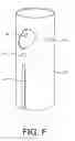
Fig. F—Internal spring loaded sliding bolts steel sleeve
Fig. G—Brass containment cylinder
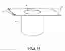
Fig. H—Brass containment face plate
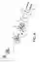
Fig. I—S. L. S. Door Knob Mechanism (Compromised)
Fig. J—S. L S. Rotating Disc (8, 9) “Weak-link” connectors unbroken
Fig. K—S. L. S. Internal locking system bolt mechanism (Locked position within door frame.)
Fig. L—S. L. S. Rotating disc (8, 9) “Weak-link” connection broken
Fig. M—S. L. S. Internal Locking System Bolt Mechanism (unlocked position within door and frame)
Unless otherwise indicated illustrations in the figures are not necessarily drawn to scale.
BRIEF SUMMARY OF THE INVENTION
A mechanized system of multiple internal spring loaded sliding bolts and internal spring loaded floating lock mechanisms located inside of the door. The S. L. S. Skiles Locking System protects the occupants and their property from unwanted intruders, harm and theft. These internal spring loaded sliding bolts and their internally located spring loaded floating locks are interconnected with and to a centrally positioned door knob mechanism and to the S. L. S. rotating discs which allow activation of the locking system mechanism either “inside or outside” of the dwelling into the locked or unlocked position. The S. L. S. Skiles Locking System is also activated inside or outside of the dwelling with either a key, “button” (inside) or “electronic keyless entry device,” allowing the door to be unlocked and opened. This can be done from either side of the door, (inside or outside) unlike the Saunders locking system, which allows operation only from the inside. The same simultaneous movement and action in the S. L. S. Locking System is accomplished (Fig. B) with all multiple internal spring loaded lock mechanisms.
When the doorknob is compromised (Fig. I) the S. L. S. mechanisms (Fig. J) will remain locked in place (Fig. K). The wire connectors between the internal spring loaded bolt locks and the S. L. S. door knob mechanism (Fig. I) will be broken by force. The steel connecting wires once separated from the S. L. S. doorknob mechanism and their respective internal spring loaded bolt locks cannot be reattached. The locked position of the S. L. S. mechanism (Fig. K) cannot be unlocked manually because the connecting wires (Fig. I) are unreachable by the intruder.
When the doorknob is compromised by force, (Fig. I) adverse pressure is applied to the mechanism and its connections. An incorporated “weak-link” (Fig. I) is built into the connecting wires. (Fig. J) This part (Fig. J) is made from a softer and weaker metal (brass) as compared to the (steel) connecting wires (Fig. J) which “connect” the S. L. S. internal spring loaded bolt locks to the S. L. S. doorknob mechanism. (Fig. I) When compromising force is applied to the S. L. S. doorknob mechanism, (Fig. I) the connecting wires (Fig. I) will separate at the “weak-link” (Fig. I) and disconnect the attachment to the S. L. S. internal spring loaded bolt locks (Fig. J) and the S. L. S. doorknob mechanism (Fig. I). When this separation occurs, the internal spring loaded bolt locks (Fig. K) will remain in the “locked” position (Fig. K) by way of the internal springs within the bolt mechanism, (Fig. K) providing continued force upon their respective bolt locks within the mechanism. (Fig. K) This “locked” position of the door within its frame (Fig. K) cannot be reversed manually or otherwise because of the disconnection of the two mechanisms (Fig. I) within the system and door.
DETAILED DESCRIPTION OF THE INVENTION
1. Internal spring loaded bolt locks are simultaneously activated by a key, button or remote electronic device.
2. When the doorknob mechanism is compromised, (Fig. I) the internal locking mechanisms will remained locked in place.
3. The S. L. S. locking mechanism with the internal spring loaded bolt locks are completely contained within a brass cylinder within the door.
Fig. A Skiles Locking System Mechanism
-
- 1. Kwikset tubular locking cylinder
- 2. Locking tumbler set (key or “electronic keyless”)
- 3. Kwikset rotating half-shaft
- 4. Kwikset round spindle
- 5. Kwikset locking mechanism
- 6. Locking spindle assembly—Kwikset
- 7. Locking spindle assembly—Kwikset
- 8. S.L. S. rotating disc for internal spring loaded floating locks
- 9. S. L. S. rotating disc for internal spring loaded sliding bolts
- 10. Attachment screws (floating lock disc to round spindle (4)
- 11. Steel connecting wires
- 12. Brass screws, Brass washers
- 13. Threaded connecting holes (attachment screws) (10)
- 14. Threaded connecting holes (attach steel connecting wires) (11)
- 15. Threaded connecting holes (attach steel connecting wires) (11)
- 16. Interior doorknob
- 17. Button lock
- 18. Connecting bolts (inside doorknob to outside doorknob assembly)
- 19. Connecting bolts (18) threaded base
Fig. B Internal spring loaded sliding bolts
-
- 20. Internal spring loaded sliding bolt
- 21. Beveled face
- 22. Floating lock retaining ring
- 23. Internal floating lock spring
- 24. Internal floating lock pin
- 25. Horizontal floating lock shaft access
- 26. Ball bearing
- 27. Ball bearing retaining hole
- 28. Floating lock separator pinion access hole
- 29. Threaded hole (for sliding bolt connecting rod (32)
- 30. Tapered point of separator pinion
- 31. Separator pinion
- 32. Sliding bolt connecting rod (threaded)
- 33. Internal spring loaded sliding bolt spring
- 34. Separator pinion connecting rod (threaded)
Fig. C S. L. S. door locking mechanism (open)
Fig. D Internal spring loaded connecting rods, connecting wires, brass end cap, and brass face plate
-
- 11. Steel connecting wires
- 32. Internal spring loaded sliding bolt connecting rod
- 33. Internal spring loaded sliding bolt spring
- 34. Internal floating lock separator pinion connecting rod
- 35. Separator pinion spring tension nut
- 36. Floating lock separator pinion spring
- 37. Separator pinion spring retaining washer
- 38. Brass end cap (attaches to brass containment cylinder)
- 39. Brass face plate mounting surface on door (mortised)
- 40. Drilled access hole for spring loaded sliding bolt assembly in door
- 41. Door edge
Fig. E Multiple internal spring loaded bolt door (closed & locked, open & unlocked position)
-
- 51. Multiple internal spring loaded sliding bolt door (closed and locked position)
- 52. Multiple internal spring loaded sliding bolt door (open and unlocked position)
Fig. F Internal spring loaded sliding bolts steel sleeve
-
- 42. Internal spring loaded sliding bolt steel sleeve
- 43. Alignment groove for ball bearing (26)
- 44. Alignment screw hole—threaded for brass containment cylinder alignment screw (47)
- 45. Internal spring loaded floating lock locking holes
Fig. G Brass containment cylinder
-
- 38. Brass containment cylinder end cap
- 44. Alignment screw hole—threaded for spring loaded sliding bolt steel sleeve
- 46. Brass containment cylinder
- 47. Steel sleeve alignment screw
Fig. H Brass containment face plate
-
- 48. Brass containment face plate
- 49. Sliding bolt access hole
- 50. Face plate holes for door application
Fig. I S. L. S. Door Knob Mechanism (Compromised)
-
- 11. Steel connecting wires
- 51. “Weak-link” connectors broken (by force)
- 52. Door
Fig. J S. L. S. Rotating Disc (8,9)
-
- 11. Steel connecting wires
- 55. “Weak-link” connectors
Fig. K S. L. S. Internal locking system bolt mechanism (Locked position within door frame.)
-
- 11. Steel connecting wires
- 20. Internal spring loaded sliding bolt
- 21. Beveled face
- 23. Internal floating lock spring
- 24. Internal floating lock pin
- 30. Tapered point of separator pinion
- 31. Separator pinion
- 32. Internal spring loaded sliding bolt connecting rod
- 33. Internal spring loaded sliding bolt spring
- 34. Internal floating lock separator pinion connecting rod
- 38. Brass end cap (attaches to brass containment cylinder)
- 39. Brass face plate mounting surface on door (mortised)
- 42. Internal spring loaded sliding bolt steel sleeve
- 45. Internal spring loaded floating lock locking holes
- 46. Brass containment cylinder
- 52. Door
- 53. Steel insertion plate
- 54. Door frame
- 56. Strike plate and screws
Fig. L S. L. S. Rotating disc (8,9)
-
- 11. Steel connecting wires (separated)
- 51. “Weak-link” connectors (broken by force)
Fig. M. S. L. S. Internal Locking System Bolt Mechanism (unlocked position within door and frame)
-
- 11. Steel connecting wires
- 20. Internal spring loaded sliding bolt
- 21. Beveled face
- 23. Internal floating lock spring
- 24. Internal floating lock pin
- 30. Tapered point of separator pinion
- 31. Separator pinion
- 32. Internal spring loaded sliding bolt connecting rod
- 33. Internal spring loaded sliding bolt spring
- 34. Internal floating lock separator pinion connecting rod
- 38. Brass end cap (attaches to brass containment cylinder)
- 39. Brass face plate mounting surface on door (mortised) 42. Internal spring loaded sliding bolt steel sleeve
- 45. Internal spring loaded floating lock locking holes
- 46. Brass containment cylinder
- 52. Door
- 53. Steel insertion plate
- 54. Door frame
- 56. Strike plate and screws
hjhkjhk
Claims
What is claimed is:1. A device comprising:
a doorknob, said doorknob comprising, at least one of, an interior doorknob with a button lock and an exterior doorknob, wherein said doorknob is configured to install on a surface of a door;
a first rotating disc implement, in which said first rotating disc is coupled to said interior doorknob;
a first steel connecting wire, wherein one proximate end of said first steel connecting wire is into engagement with said first rotating disc implement, while another proximate end of said first steel connecting wire is into engagement with a first connecting rod;
wherein said first connecting rod comprises at least a spring loaded sliding bolt connecting rod configured to engage a threaded hole of a sliding bolt, wherein said first connecting rod is into engagement with the other proximate end of said first steel connecting wire;
a second rotating disc implement, wherein said second rotating disc implement is generally coupled to said exterior doorknob;
a second steel connecting wire, wherein one proximate end of said second steel connecting wire is into engagement with said second rotating disc implement, while another proximate end of said second steel connecting wire is into engagement with a second connecting rod;
wherein said second connecting rod comprises at least a separator pinion connecting rod configured to engage a separator pinion in said sliding bolt, wherein said second connecting rod is into engagement with the other end of said second steel connecting wire;
a first weak-link connector, wherein said first weak-link connector is disposed on a proximate middle portion of said first steel connecting wire, and wherein said first weak-link connector is configured to disable said first steel connecting wire when an excessive force is applied to said doorknob; and,
a second weak-link connector disposed on a proximate middle portion of said second steel connecting wire, wherein said second weak-link connector is configured to generally disable said second steel connecting wire when an excessive force is applied to said doorknob, wherein said sliding bolt is into engagement with said spring loaded sliding bolt connecting rod and said separator pinion connecting rod, wherein said sliding bolt comprising at least a spring loaded sliding bolt operable to enable said device to position in a locked or unlocked condition.
2. The device of claim 1, wherein said doorknob is configured to install in the center of said door.
3. The device of claim 1, wherein said device is configured to install on a surface of said door wherein said door is made of wood.
4. The device of claim 1, wherein said device is configured to install on a surface of said door wherein said door is made of steel.
5. The device of claim 1, wherein said device comprises means for securing said door to a door frame.
6. The device of claim 5, wherein said device is configured to secure said door to said door frame wherein said door frame is made of wood.
7. The device of claim 5, wherein said device is configured to secure said door to said door frame wherein said door frame is made of steel.
Images & Drawings included:


Sources:
- United States Patent and Trademark Office - verify current appl. status at the USPTO↗
Similar patent applications:
- » 20190304227
Wireless door lock device and biometric door lock controlling system having the wireless door lock device - » 20110101840
Door-locking device for a household appliance, door arrangement comprising a door-locking device and method for locking a door of a household appliance - » 20180202191
Door locking device, in particular an electromagnetic door locking device - » 20210090364
Door lock device and control method for door lock device - » 20220123488
Vehicle door lock device and method of manufacturing vehicle door lock device - » 20210238888
DOOR-LOCK DEVICE AND HOUSEHOLD APPLIANCE EQUIPPED WITH SUCH DOOR-LOCK DEVICE - » 20220178171
Door lock device and door lock having the same - » 20210087859
Vehicle door locking device and vehicle door locking set - » 20210180370
Vehicular door lock device and vehicular door lock system - » 20210082214
Method, system, and door lock device for controlling door lock
Recent applications in this class:
- » 20250052098 2025-02-13
LOCKING SYSTEM FOR DOORS AND WINDOWS - » 20230349207 2023-11-02
Locking system for doors and windows - » 20220213723 2022-07-07
Door lock adapter - » 20220170299 2022-06-02
Child proof latch and method of fitting - » 20210355723 2021-11-18
Latching System for Door or Window Panel - » 20210198926 2021-07-01
Integrated latch mechanism for securing rackmount equipment in a chassis - » 20200399939 2020-12-24
Contact-minimizing door opening and closing system - » 20200190874 2020-06-18
Latch mechanism - » 20190218837 2019-07-18
Pin latch with adjustable pre-load - » 20180209185 2018-07-26
Aircraft lavatory door latch