Imaging lens assembly
US20190121097A1
2019-04-25
16/224,713
2018-12-18
✅ Patent granted
US 10,996,439 B2
2021-05-04
-
-
Marin Pichler
Hauptman Ham, LLP
2039-05-27
Abstract:
The present disclosure discloses an imaging lens assembly. The imaging lens assembly includes sequentially from as object side to as image side: a first lens, having a positive refractive power; a second lens, having a negative refractive power, an object-side surface of the second lens being a convex surface, and an image-side surface of the second lens being a concave surface; a third lens, having a positive refractive power, and an image-side surface of the third lens being a convex surface; a fourth lens, having a refractive power; and a fifth lens, having a refractive power, an object-side surface of the fifth lens being a convex surface. An effective focal length f of the imaging lens assembly and an effective focal length f1 of the first lens satisfy: 5.5<f1/f<25. The imaging lens assembly has the characteristics of large aperture, high relative brightness, wide angle, and good image quality.
Assignee:
- Zhejiang Sunny Optical Co., Ltd 106 🇨🇳 Ningbo, China
Applicant:
Interested in similar patents?
Get notified when new applications in this technology area are published.
Classification:
G02B13/0045 » CPC main
Optical objectives specially designed for the purposes specified below; Miniaturised objectives for electronic devices, e.g. portable telephones, webcams, PDAs, small digital cameras characterised by the lens design having at least one aspherical surface having five or more lenses
H04N5/2254 » CPC further
Details of television systems; Studio circuitry; Studio devices; Studio equipment ; Cameras comprising an electronic image sensor, e.g. digital cameras, video cameras, TV cameras, video cameras, camcorders, webcams, camera modules for embedding in other devices, e.g. mobile phones, computers or vehicles; Television cameras ; Cameras comprising an electronic image sensor, e.g. digital cameras, video cameras, camcorders, webcams, camera modules specially adapted for being embedded in other devices, e.g. mobile phones, computers or vehicles; Constructional details Mounting of optical parts, e.g. lenses, shutters, filters or optical parts peculiar to the presence or use of an electronic image sensor
G02B13/00 IPC
Optical objectives specially designed for the purposes specified below
G02B9/60 » CPC further
Optical objectives characterised both by the number of the components and their arrangements according to their sign, i.e. + or - having five components only
G02B13/06 » CPC further
Optical objectives specially designed for the purposes specified below Panoramic objectives; So-called "sky lenses" including panoramic objectives having reflecting surfaces
H04N5/225 IPC
Details of television systems; Studio circuitry; Studio devices; Studio equipment ; Cameras comprising an electronic image sensor, e.g. digital cameras, video cameras, TV cameras, video cameras, camcorders, webcams, camera modules for embedding in other devices, e.g. mobile phones, computers or vehicles Television cameras ; Cameras comprising an electronic image sensor, e.g. digital cameras, video cameras, camcorders, webcams, camera modules specially adapted for being embedded in other devices, e.g. mobile phones, computers or vehicles
G02B13/04 » CPC further
Optical objectives specially designed for the purposes specified below Reversed telephoto objectives
Description
CROSS-REFERENCE TO RELATED APPLICATIONS
This application is a continuation of International Application. PCT/CN2018/077349, with an international filing date of Feb. 27, 2018, which claims priority to Chinese Patent Application no. 201710637489.7, filed with the China National Intellectual Property Administration (CNIPA) on Jul. 31, 2017, and Chinese Patent Application no. 201720938617.7, filed with the China National Intellectual Property Administration (CNIPA) on Jul. 31, 2017, the contents of which are incorporated herein by reference in their entirety.
TECHNICAL FIELD
The present disclosure relates to an imaging lens assembly, and specifically to a large aperture imaging lens assembly including five lenses.
BACKGROUND
In addition to the development trend of high resolution, modern optical systems continually develop towards a large field-of-view and a large aperture, which can receive more information from the object side. Therefore, large field-of-view and large aperture camera lens assemblies are the trend.
In recent years, higher performance of the camera lens assemblies is required, such as a large field-of-view, a large aperture, high relative brightness, and high image quality, due to the increasing development of portable electronic products. A F-number of an existing lens assembly is typically configured as 2.0 or higher to satisfy the requirements of compact structure and high relative brightness, thereby obtaining the lens assembly having a compact structure and high optical performance. However, even higher performance of the imaging lens assembly is required with the constant development of smart phones and other portable electronic products, especially in the situations in which light is insufficient (e.g., cloudy and rainy days, dusk), or the hand is trembling. The F-number of 2.0 or higher cannot meet the even higher requirements for imaging.
Therefore, the present disclosure provides an optical system applicable to the portable electronic products and having a large aperture, high relative brightness, a wide angle, high image quality, and low sensitivity.
SUMMARY
The present disclosure provides an imaging lens assembly in order to solve at least one problem in the existing technology.
According to an aspect, the present disclosure provides an imaging lens assembly. The imaging lens assembly includes sequentially from an object side to an image side: a first lens, having a positive refractive power; a second lens, having a negative refractive power, an object-side surface of the second lens being a convex surface, and an image-side surface of the second lens being a concave surface; a third lens, having a positive refractive power, and an image-side surface of the third lens being a convex surface; a fourth lens, having a refractive power; and a fifth lens, having a refractive power, and an object-side surface of the fifth lens being a convex surface. An effective focal length f of the imaging lens assembly and an effective focal length f1 of the first lens satisfy: 5.5<f1/f<25.
According to an implementation of the present disclosure, the effective focal length f of the imaging lens assembly and an entrance pupil diameter EPD of the imaging lens assembly satisfy: f/EPD<1.6.
According to an implementation of the present disclosure, an effective radius DT11 of an object-side surface of the first lens and an effective radius DT52 of an image-side surface of the fifth lens satisfy: 1.8<DT11/DT52<2.8.
According to an implementation of the present disclosure, an effective radius DT11 of an object-side surface of the first lens and half of a diagonal length ImgH of an effective pixel area on an image plane satisfy: 1.3<DT11/ImgH<3.
According to an implementation of the present disclosure, a combined focal length f12 of the first lens and the second lens and the effective focal length f of the imaging lens assembly satisfy: −3.5<f12/f<31 2.6.
According to an implementation of the present disclosure, a radius of curvature R3 of the object-side surface of the second lens and a radius of curvature R6 of the image-side surface of the third lens satisfy: −1.2<R3/R6<−0.5.
According to an implementation of the present disclosure, at least one surface of the object-side surface and an image-side surface of the first lens has at least one inflection point.
According to an implementation of the present disclosure, the half of the diagonal length ImgH of the effective pixel area on the image plane and the effective focal length f of the imaging lens assembly satisfy: ImgH/f≤1.1.
According to an implementation of the present disclosure, the effective focal length f1 of the first lens and an effective focal length f3 of the third lens satisfy: 1.5<f1/f3<8.
According to an implementation of the present disclosure, an effective focal length f3 of the third lens and the effective focal length f of the imaging lens assembly satisfy: 1.4≤f3/f<3.8.
According to an implementation of the present disclosure, an effective radius DT11 of an object-side surface of the first lens and an effective radius DT21 of the object-side surface of the second lens satisfy: 2<DT11/DT21<3.4.
According to an implementation of the present disclosure, an effective focal length f5 of the fifth lens and the effective focal length f of the imaging lens assembly satisfy: |f/f5|<0.2.
According to an implementation of the present disclosure, an infrared band-pass optical filter is disposed between the fifth lens and an image plane.
According to an implementation of the present disclosure, a diaphragm is disposed between the second lens and the third lens.
According to another aspect, the present disclosure provides an imaging lens assembly. The imaging lens assembly includes sequentially from an object side to an image side: a first lens, having a positive refractive power; a second lens, having a negative refractive power, an object-side surface of the second lens being a convex surface, and an image-side surface of the second lens being a concave surface; a third lens, having a positive refractive power, and an image-side surface of the third lens being a convex surface; a fourth lens, having a refractive power; and a fifth lens, having a refractive power, and an object-side surface of the fifth lens being a convex surface. An effective radius DT11 of an object-side surface of the first lens and half of a diagonal length ImgH of an effective pixel area on an image plane satisfy: 1.3<DT11/ImgH<3.
According to an implementation of the present disclosure, an effective focal length f of the imaging lens assembly and an entrance pupil diameter EPD of the imaging lens assembly satisfy: f/EPD≤1.6.
According to an implementation of the present disclosure, the effective radius DT11 of the object-side surface of the first lens and an effective radius DT52 of an image-side surface of the fifth lens satisfy: 1.8<DT11/DT52<2.8.
According to an implementation of the present disclosure, the effective focal length f of the imaging lens assembly and an effective focal length f1 of the first lens satisfy: 5.5<f1/f<25.
According to an implementation of the present disclosure, a combined focal length f12 of the first lens and the second lens and an effective focal length f of the imaging lens assembly satisfy: −3.5<f12/f<−2.6.
According to an implementation of the present disclosure, a radius of curvature R3 of the object-side surface of the second lens and a radius of curvature R6 of the image-side surface of the third lens satisfy: −1.2<R3/R6<−0.5.
According to an implementation of the present disclosure, at least one surface of the object-side surface and an image-side surface of the first lens has at least one inflection point.
According to an implementation of the present disclosure, the half of the diagonal length ImgH of the effective pixel area on the image plane and the effective focal length f of the imaging lens assembly satisfy: ImgH/f≥1.1.
According to an implementation of the present disclosure, the effective focal length f1 of the first lens and an effective focal length f3 of the third lens satisfy: 1.5<f1/f3<8.
According to an implementation of the present disclosure, an effective focal length f3 of the third lens and the effective focal length f of the imaging lens assembly satisfy: 1.4.≤f3/f<3.8.
According to an implementation of the present disclosure, the effective radius DT11 of the object-side surface of the first lens and an effective radius DT21 of the object-side surface of the second lens satisfy: 2<DT11/DT21<3.4.
According to an implementation of the present disclosure, an effective focal length f5 of the fifth lens and an effective focal length f of the imaging lens assembly satisfy: |f/f5|<0.2.
According to an implementation of the present disclosure, an infrared band-pass optical filter is disposed between the fifth lens and the image plane.
According to an implementation of the present disclosure, a diaphragm is disposed between the second lens and the third lens.
According to another aspect, the present disclosure provides an imaging lens assembly. The imaging lens assembly includes sequentially from an object side to an image side: a first lens, having a positive refractive power; a second lens, having a negative refractive power, an object-side surface of the second lens being a convex surface, and an image-side surface of the second lens being a concave surface; a third lens, having a positive refractive power, and an image-side surface of the third lens being a convex surface; a fourth lens, having a refractive power; and a fifth lens, having a refractive power, and an object-side surface of the fifth lens being a convex surface. An effective radius DT11 of an object-side surface of the first lens and an effective radius DT52 of an image-side surface of the fifth lens satisfy: 1.8<DT11/DT52<2.8.
According to another aspect, the present disclosure provides an imaging lens assembly. The imaging lens assembly includes sequentially from an object side to an image side: a first lens, having a positive refractive power; a second lens, having a negative refractive power, an object-side surface of the second lens being a convex surface, and an image-side surface of the second lens being a concave surface; a third lens, having a positive refractive power, and an image-side surface of the third lens being a convex surface; a fourth lens, having a refractive power; and a fifth lens, having a refractive power, and an object-side surface of the fifth lens being a convex surface. A combined focal length f12 of the first lens and the second lens and an effective focal length f of the imaging lens assembly satisfy: −3.5<f12/f<−2.6.
According to another aspect, the present disclosure provides an imaging lens assembly. The imaging lens assembly includes sequentially from an object side to an image side: a first lens, having a positive refractive power; a second lens, having a negative refractive power, an object-side surface of the second lens being a convex surface, and an image-side surface of the second lens being a concave surface; a third lens, having a positive refractive power, and an image-side surface of the third lens being a convex surface; a fourth lens, having a refractive power; and a fifth lens, having a refractive power, and an object-side surface of the fifth lens being a convex surface. An effective radius DT11 of an object-side surface of the first lens and an effective radius DT21 of the object-side surface of the second lens satisfy: 2<DT11/DT21<3.4.
According to another aspect, the present disclosure provides an imaging lens assembly. The imaging lens assembly includes sequentially from an object side to an image side: a first lens, having a positive refractive power; a second lens, having a negative refractive power, an object-side surface of the second lens being a convex surface, and an image-side surface of the second lens being a concave surface; a third lens, having a positive refractive power, and an image-side surface of the third lens being a convex surface; a fourth lens, having a refractive power; and a fifth lens, having a refractive power, and an object-side surface of the fifth lens being a convex surface. An effective focal length f5 of the fifth lens and an effective focal length f of the imaging lens assembly satisfy: |f/f5|<0.2.
The imaging lens assembly according to the present disclosure uses five lenses, and has at least one of the characteristics of a large aperture, high relative brightness, a wide angle, and high image quality.
BRIEF DESCRIPTION OF THE DRAWINGS
After reading detailed descriptions of non-limiting implementations with reference to the accompanying drawings, other features, objectives and advantages of the present disclosure will become more apparent. In the accompanying drawings:
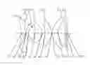
FIG. 1 is a schematic structural diagram illustrating an imaging lens assembly according to the first embodiment;
FIGS. 2-5 respectively illustrate a longitudinal aberration curve, an astigmatic curve, a distortion curve, and a relative illumination curve of the imaging lens assembly according to the first embodiment;
FIG. 6 is a schematic structural diagram illustrating an imaging lens assembly according to the second embodiment;
FIGS. 7-10 respectively illustrate a longitudinal aberration curve, an astigmatic curve, a distortion curve, and a relative illumination curve of the imaging lens assembly according to the second embodiment;
FIG. 11 is a schematic structural diagram illustrating an imaging lens assembly according to the third embodiment;
FIGS. 12-15 respectively illustrate a longitudinal aberration curve, an astigmatic curve, a distortion curve, and a relative illumination curve of the imaging lens assembly according to the third embodiment;
FIG. 16 is a schematic structural diagram illustrating an imaging lens assembly according to the fourth embodiment;
FIGS. 17-20 respectively illustrate a longitudinal aberration curve, an astigmatic curve, a distortion curve, and a relative illumination curve of the imaging lens assembly according to the fourth embodiment;
FIG. 21 is a schematic structural diagram illustrating an imaging lens assembly according to the fifth embodiment;
FIGS. 22-25 respectively illustrate a longitudinal aberration curve, an astigmatic curve, a distortion curve, and a relative illumination curve of the imaging lens assembly according to the fifth embodiment;
FIG. 26 is a schematic structural diagram illustrating an imaging lens assembly according to the sixth embodiment; and
FIGS. 27-30 respectively illustrate a longitudinal aberration curve, an astigmatic curve, a distortion curve, and a relative illumination curve of the imaging lens assembly according to the sixth embodiment.
DETAILED DESCRIPTION OF EMBODIMENTS
The present disclosure will be further described in detail below with reference to the accompanying drawings and embodiments. It may be understood that the specific embodiments described herein are merely used to explain the related invention rather than limit the invention. It should also be noted that for the convenience of description, only the parts related to the related invention are shown in the accompanying drawings.
It should be understood that in the present disclosure, an element or layer may be directly on another element or layer, or directly connected to or coupled to another element or layer, or there may be an intervening element or layer, when the element or layer is described as being “on,” “connected to,” or “coupled to” another element or layer. When an element is referred to as being “directly on,” “directly connected to,” or “directly coupled to” another element or layer, there are no intervening elements or layers. Throughout the specification, identical reference numerals refer to the same elements. The expression “and/or” used in this text includes any and all combinations of one or more of the associated listed items.
It should be understood that although the terms 1st, 2nd or first, second, etc. may be used herein to describe various elements, components, areas, layers, and/or sections, these elements, components, areas, layers, and/or sections should not be limited by these terms. These terms are only used to distinguish one element, component, area, layer, or section from another element, component, area, layer, or section. Thus, the first element, component, area, layer, or section discussed below may be termed the second element, component, area, layer, or section without departing from the teachings of the present disclosure.
The terminology used herein is for the purpose of describing specific implementations only and is not intended to limit the present disclosure. As used herein, unless explicitly stated otherwise in the context, use of a term in a singular form also encompasses that term in plural form. It should be further understood that the terms “comprising,” “including,” “having,” and variants thereof, when used in this specification, specify the presence of stated features, entireties, steps, operations, elements and/or components, but do not exclude the presence or addition of one or more other features, entireties, steps, operations, elements, components and/or combinations thereof. As used herein, the term “and/or” includes any and all combinations of one or more of the associated listed items. Expressions, such as “at least one of,” when preceding a list of elements, modify the entire list of elements rather than the individual element in the list. Further, the use of “may,” when describing the implementations of the present disclosure, relates to “one or more implementations of the present disclosure.” In addition, the term “exemplary” is intended to refer to an example or illustration.
Unless otherwise defined, all terms (including technical and scientific terms) used herein have the same meaning as commonly understood by those of ordinary skill in the art to which the present disclosure belongs. It should be further understood that terms, such as those defined in commonly used dictionaries, should be interpreted as having a meaning that is consistent with their meaning in the context of the relevant art and will not be interpreted in an idealized or overly formal sense unless expressly so defined herein.
It should be noted that the embodiments in the present disclosure and the features in the embodiments may be combined with each other on a non-conflict basis. The present disclosure will be described below in detail with reference to the accompanying drawings and in combination with the embodiments.
The present disclosure provides an imaging lens assembly. The imaging lens assembly according to the present disclosure from an object side of the imaging lens assembly to an image side is sequentially provided with: a first lens, a second lens, a third lens, a fourth lens, and a fifth lens.
In the embodiments of the present disclosure, an effective focal length f of the imaging lens assembly and an entrance pupil diameter EPD of the imaging lens assembly satisfy: f/EPD≤1.6, and the effective focal length f of the imaging lens assembly and an effective focal length f1 of the first lens satisfy: 5.5<f1/f<25, specifically, satisfy: 5.82≤f1/f≤12.05. An imaging lens assembly satisfying the above relationship can achieve the effects of wide angle, large aperture, high relative illumination, and high resolution.
In the embodiments of the present disclosure, an effective radius DT11 of an object-side surface of the first lens and an effective radius DT52 of an image-side surface of the fifth lens satisfy: 1.8<DT11/DT52<2.8, and more specifically, satisfy: 1.86≤DT11/DT52≤2.75. An imaging lens assembly satisfying the above relationship can achieve the effects of wide angle and high relative illumination.
In the embodiments of the present disclosure, the effective radius DT11 of the object-side surface of the first lens and half of a diagonal length ImgH of an effective pixel area on an image plane satisfy: 1.3<DT11/ImgH<3, and more specifically, satisfy: 1.31≤DT11/ImgH≤2.89. An imaging lens assembly satisfying the above relationship can achieve the effects of wide angle and high relative illumination.
In the embodiments of the present disclosure, a combined focal length f12 of the first lens and the second lens and the effective focal length f of the imaging lens assembly satisfy: −3.5<f12/f<−2.6, and more specifically, satisfy: −3.4≤f12/f≤−2.48. An imaging lens assembly satisfying the above relationship can achieve the effect of wide angle.
In the embodiments of the present disclosure, a radius of curvature R3 of the object-side surface of the second lens and a radius of curvature R6 of the image-side surface of the third lens satisfy: −-1.2<R3/R6<−0.5, and more specifically, satisfy: −1.1≤R3/R6≤−0.6. An imaging lens assembly satisfying the above relationship can achieve the effects of large aperture and high image quality.
In the embodiments of the present disclosure, the effective focal length f1 of the first lens and an effective focal length f3 of the third lens satisfy: 1.5<f1/f3<8, and more specifically, satisfy: 1.6≤f1/f3≤5.02. An imaging lens assembly satisfying the above relationship can achieve the effects of wide angle and high pixel.
In the embodiments of the present disclosure, the half of the diagonal length ImgH of the effective pixel area on the image plane and the effective focal length f of the imaging lens assembly satisfy: ImgH/f≥1.1, and more specifically, satisfy: ImgH/f≥1.11. An imaging lens assembly satisfying the above relationship can achieve the effect of wide angle.
In the embodiments of the present disclosure, the effective focal length f3 of the third lens and the effective focal length f of the imaging lens assembly satisfy: 1.4≤f3/f<3.8, and more specifically, satisfy: 1.421≤f3/f≤3.63. An imaging lens assembly satisfying the above relationship can achieve the effects of high image quality and wide angle.
In the embodiments of the present disclosure, the effective radius DT11 of the object-side surface of the first lens and an effective radius DT21 of the object-side surface of the second lens satisfy: 2<DT11/DT21<3.4, and more specifically, satisfy: 2.06≤DT11/DT21≤3.28. An imaging lens assembly satisfying the above relationship can achieve the effect of wide angle.
In the embodiments of the present disclosure, an effective focal length f5 of the fifth lens and the effective focal length f of the imaging lens assembly satisfy: |f/f5|<0.2, and more specifically, satisfy: |f/f5|≤0.18. An imaging lens assembly satisfying the above relationship can achieve the effect of high relative illumination.
In the embodiments of the present disclosure, an infrared band-pass optical filter is disposed between the fifth lens and the image plane. The infrared waveband contributes to not introducing chromatic aberration into the system and controlling the diffuse spot diameter. At the same time, the infrared waveband contributes to reducing the interference of ambient visible light and improving the signal to noise ratio of the image-side sensor output.
In the embodiments of the present disclosure, at least one surface of the object-side surface and an image-side surface of the first lens has at least one inflection. point, which helps reduce the distortion.
The imaging lens assembly according to the first to the sixth embodiments of the present disclosure includes five lenses. These five lenses are respectively a first lens E1 having an object-side surface S1 and an image-side surface S2, a second lens E2 having an object-side surface S3 and an image-side surface S4, a third lens E3 having an object-side surface S5 and an image-side surface S6, a fourth lens E4 having an object-side surface S7 and an image-side surface S8, and a fifth lens E5 having an object-side surface S9 and an image-side surface S10. The first to the fifth lenses E1-E5 are arranged in sequence from an object side to an image side of the imaging lens assembly. The first lens E1 may have a positive refractive power, and at least one surface of the object-side surface and the image-side surface of the first lens has at least one inflection point. The second lens E2 may have a negative refractive power, the object-side surface S3 of the second lens is a convex surface, and the image-side surface S4 of the second lens is a concave surface. The third lens E3 may have a positive refractive power, and the image-side surface S6 of the third lens is a convex surface. The fourth lens E4 may have a positive refractive power. The fifth lens E5 may have a positive refractive power or a negative refractive power. The imaging lens assembly further includes an optical filter E6 having an object-side surface S11 and an image-side surface S12 for filtering infrared light. The imaging lens assembly further includes a diaphragm disposed between the second lens E2 and the third lens E3, in the embodiments, light from an object passes through the surfaces S1 to S12 sequentially and is finally imaged on the image plane S13.
| TABLE 1 | |
| embodiment |
| parameters | 1 | 2 | 3 | 4 | 5 | 6 |
| ImgH (mm) | 2.47 | 2.47 | 2.47 | 2.47 | 2.47 | 3.01 |
| HFOV (°) | 56.23 | 55.36 | 51.31 | 54.55 | 53.47 | 51.19 |
| f (mm) | 2.20 | 2.18 | 1.99 | 2.19 | 2.12 | 2.71 |
| f1 (mm) | 15.67 | 13.64 | 24.01 | 12.74 | 13.87 | 18.40 |
| f2 (mm) | −5.38 | −4.21 | −5.54 | −4.50 | −4.29 | −5.48 |
| f3 (mm) | 3.13 | 6.55 | 6.16 | 7.95 | 6.18 | 7.86 |
| f4 (mm) | 11.72 | 4.39 | 4.12 | 3.65 | 4.22 | 4.93 |
| f5 (mm) | 12.49 | 18.55 | −94.74 | 630.30 | 12.67 | 34.51 |
| TTL (mm) | 7.67 | 8.50 | 10.49 | 9.08 | 8.14 | 10.71 |
In the embodiments of the present disclosure, the first to the fifth lenses E1 to E5 have their respective effective focal lengths f1 to f5. The first to the fifth lenses E1 to E5 are sequentially arranged along an optical axis and collectively determine the total effective focal length f of the imaging lens assembly. The effective focal lengths f1 to f5 of the first to the fifth lenses E1 to E5, the total effective focal length f of the imaging lens assembly, the total track length TTL of the imaging lens assembly, the half of the maximal field-of-view HFOV of the imaging lens assembly, and the half of the diagonal length ImgH of the effective pixel area on the image plane in the first embodiment to the fifth embodiment may be, for example, those shown in Table 1 above.
The present disclosure is further described in detail below in combination with the specific embodiments.
The First Embodiment
FIG. 1 is a schematic structural diagram illustrating the imaging lens assembly of the first embodiment. As described above and with reference to FIG. 1, the imaging lens assembly according to the first embodiment includes five lenses. The five lenses are respectively the first lens E1 having the object-side surface S1 and the image-side surface S2, the second lens E2 having the object-side surface S3 and the image-side surface S4, the third lens E3 having the object-side surface S5 and the image-side surface S6, the fourth lens E4 having the object-side surface S7 and the image-side surface S8, and the fifth lens E5 having the object-side surface S9 and the image-side surface S10.
Table 2 shows the surface type, the radius of curvature, the thickness, the refractive index, the abbe number, and the conic coefficient of each lens in the imaging lens assembly in this embodiment. The radius of curvature and the thickness are shown in millimeters (mm).
| TABLE 2 | ||
| material |
| surface | surface | radius of | refractive | abbe | conic | |
| number | type | curvature | thickness | index | number | coefficient |
| OBJ | spherical | infinite | infinite | |||
| S1 | aspheric | −2.0173 | 0.6966 | 1.53 | 55.8 | −11.6621 |
| S2 | aspheric | −1.8139 | 0.0363 | −12.5743 | ||
| S3 | aspheric | 1.5941 | 0.4102 | 1.62 | 23.5 | −4.8569 |
| S4 | aspheric | 0.9718 | 0.6786 | −3.8558 | ||
| STO | spherical | infinite | 0.3706 | |||
| S5 | aspheric | −16174.9841 | 1.2097 | 1.53 | 55.8 | −99.0000 |
| S6 | aspheric | −1.6444 | 0.5327 | −0.1620 | ||
| S7 | aspheric | −1.9661 | 1.1180 | 1.53 | 55.8 | −11.7887 |
| S8 | aspheric | −1.7832 | 0.0300 | −0.6817 | ||
| S9 | aspheric | 1.5386 | 0.9986 | 1.53 | 55.8 | −4.7613 |
| S10 | aspheric | 1.5593 | 1.1768 | −2.9206 | ||
| S11 | spherical | infinite | 0.2100 | 1.51 | 64.2 | |
| S12 | spherical | infinite | 0.1985 | |||
| S13 | spherical | infinite | ||||
In this embodiment, the surface type x of each aspheric surface is defined by the below formula (1):
x = ch 2 1 + 1 - ( k + 1 ) c 2 h 2 + ∑ Aih i ( 1 )
Here, x is the sag the axis-component of the displacement of the surface from the aspheric vertex, when the surface is at height h from the optical axis; c is the paraxial curvature of the aspheric surface, and c=1/R (i.e., the paraxial curvature c is the reciprocal of the radius of curvature R in Table 2 above) ; k is the conic coefficient (given in Table 2 above); and Ai is the correction coefficient of the ith order of the aspheric surface. Table 3 below shows the higher-order coefficients A4, A6, A8, A10, A12, A14, and A16 applicable to the aspheric surfaces S1-S10 of the aspheric lenses in this embodiment.
| TABLE 3 | |||||||
| surface | |||||||
| number | A4 | A6 | A8 | A10 | A12 | A14 | A16 |
| S1 | −4.9089E−02 | 4.8674E−01 | −4.6896E+00 | 2.5620E+01 | −8.6729E+01 | 1.8321E+02 | −2.3553E+02 |
| S2 | −1.0662E−02 | 2.0801E−02 | −2.8151E+00 | 2.1883E+01 | −1.0415E+02 | 3.0157E+02 | −5.2395E+02 |
| S3 | −2.6526E−01 | 3.2853E−01 | −5.3928E+00 | 4.0465E+01 | −1.9272E+02 | 5.7966E+02 | −1.0628E+03 |
| S4 | −1.8173E−02 | −2.2361E−01 | 2.3298E+00 | −1.5195E+01 | 6.5109E+01 | −1.6769E+02 | 2.5812E+02 |
| S5 | −8.7746E−02 | 2.3830E−02 | 9.9586E−01 | −7.8194E+00 | 3.3087E+01 | −7.9110E+01 | 1.1006E+02 |
| S6 | −2.3238E−01 | 6.3312E−01 | −1.5467E+00 | 3.6129E+00 | −6.1881E+00 | 7.2066E+00 | −5.1493E+00 |
| S7 | −5.8897E−01 | 6.0048E−01 | −3.9682E−01 | 2.0766E−01 | −8.2185E−02 | 2.2711E−02 | −4.0942E−03 |
| S8 | −3.0468E−01 | 3.1884E−01 | −2.4608E−01 | 1.3565E−01 | −5.1678E−02 | 1.3066E−02 | −2.0669E−03 |
| S9 | −3.0468E−01 | 3.1884E−01 | −2.4608E−01 | 1.3565E−01 | −5.1678E−02 | 1.3066E−02 | −2.0669E−03 |
| S10 | −3.0468E−01 | 3.1884E−01 | −2.4608E−01 | 1.3565E−01 | −5.1678E−02 | 1.3066E−02 | −2.0669E−03 |
FIG. 2 shows a longitudinal aberration curve of the imaging lens assembly according to the first embodiment, representing deviations of focal points of light of different wavelengths converged after passing through the optical system. FIG. 3 shows an astigmatic curve of the imaging lens assembly according to the first embodiment, representing a curvature of a tangential image plane and a curvature of a sagittal image plane. FIG. 4 shows a distortion curve of the imaging lens assembly according to the first embodiment, representing amounts of distortion at different viewing angles. FIG. 5 shows a relative illumination curve of the imaging lens assembly according to the first embodiment, representing a ratio of peripheral image brightness to center image brightness, reflecting brightness uniformity of the image. In summary and referring to FIG. 2 to FIG. 5, it may be seen that the imaging lens assembly according to the first embodiment is an imaging lens assembly having a large aperture, high relative brightness, a wide angle, and high image quality.
The Second Embodiment
FIG. 6 is a schematic structural diagram illustrating the imaging lens assembly of the second embodiment. As described above and with reference to FIG. 6, the imaging lens assembly according to the second embodiment includes the first lens E1, the second lens E2, the third lens E3, the fourth lens E4, and the fifth lens E5 in sequence from an object side to an image side.
Table 4 shows the surface type, the radius of curvature, the thickness, the refractive index, the abbe number, and the conic coefficient of each lens in the imaging lens assembly in this embodiment. The radius of curvature and the thickness are shown in millimeters (mm).
| TABLE 4 | ||||
| radius | material |
| surface | surface | of cur- | thick- | refractive | abbe | conic |
| number | type | vature | ness | index | number | coefficient |
| OBJ | spherical | infinite | infinite | |||
| S1 | aspheric | −2.3373 | 1.0210 | 1.53 | 55.8 | −8.2837 |
| S2 | aspheric | −2.0289 | 0.1104 | −14.5563 | ||
| S3 | aspheric | 3.4698 | 0.6458 | 1.62 | 23.5 | 1.2441 |
| S4 | aspheric | 1.3824 | 0.8009 | 0.0156 | ||
| STO | spherical | infinite | 0.5421 | |||
| S5 | aspheric | 11.9613 | 1.2676 | 1.53 | 55.8 | 3.9689 |
| S6 | aspheric | −4.6623 | 0.1583 | 3.9839 | ||
| S7 | aspheric | 3.3498 | 1.4003 | 1.53 | 55.8 | −6.1902 |
| S8 | aspheric | −6.3859 | 0.5733 | 0.8792 | ||
| S9 | aspheric | 1.8592 | 1.0404 | 1.53 | 55.8 | −0.8903 |
| S10 | aspheric | 1.8534 | 0.9387 | −1.9598 | ||
| S11 | spherical | infinite | 0.2100 | 1.51 | 64.2 | |
| S12 | spherical | infinite | 0.1103 | |||
| S13 | spherical | infinite | ||||
Table 5 below shows the higher-order coefficients A4, A6, A8, A10, A12, A14, and A16 applicable to the aspheric surfaces S1-S10 of the aspheric lenses in this embodiment. Here, the surface types of the aspheric surfaces may be defined by the formula (1) given above in the first embodiment.
| TABLE 5 | |||||||
| surface | |||||||
| number | A4 | A6 | A8 | A10 | A12 | A14 | A16 |
| S1 | 1.3444E−02 | −2.1683E−03 | 2.6176E−04 | −2.0196E−05 | 9.4504E−07 | −2.4285E−08 | 2.6692E−10 |
| S2 | 1.4391E−02 | −3.1393E−03 | 5.7988E−04 | −7.1213E−05 | 5.2216E−06 | −2.0165E−07 | 3.1301E−09 |
| S3 | 3.3415E−02 | −6.8953E−02 | 5.2354E−02 | −2.3181E−02 | 5.9166E−03 | −8.1041E−04 | 4.5750E−05 |
| S4 | −1.4153E−01 | 2.4727E−01 | −4.6011E−01 | 6.1033E−01 | −4.9301E−01 | 2.1376E−01 | −3.7935E−02 |
| S5 | −1.1570E−03 | −5.7705E−03 | 3.3514E−03 | −1.5279E−03 | 4.0230E−04 | −4.4255E−05 | 3.2768E−07 |
| S6 | −4.2088E−02 | 1.4316E−02 | −6.5834E−03 | 1.8045E−03 | −2.6685E−04 | 7.5067E−06 | 1.7583E−06 |
| S7 | −1.5253E−02 | 1.1563E−02 | −5.6169E−03 | 1.6007E−03 | −2.5882E−04 | 2.1654E−05 | −7.2460E−07 |
| S8 | −4.0492E−02 | 2.3683E−02 | −8.3671E−03 | 1.9269E−03 | −2.5104E−04 | 1.5829E−05 | −3.4332E−07 |
| S9 | −7.6142E−02 | 1.5510E−02 | −1.0099E−02 | 4.3318E−03 | −9.0325E−04 | 9.2739E−05 | −3.8153E−06 |
| S10 | 8.3394E−03 | −3.1734E−02 | 1.5169E−02 | −4.1147E−03 | 6.6814E−04 | −5.8466E−05 | 2.0611E−06 |
FIG. 7 shows a longitudinal aberration curve of the imaging lens assembly according to the second embodiment, representing deviations of focal points of light of different wavelengths converged after passing through the optical system. FIG. 8 shows an astigmatic curve of the imaging lens assembly according to the second embodiment, representing a curvature of a tangential image plane and a curvature of a sagittal image plane. FIG. 9 shows a distortion curve of the imaging lens assembly according to the second embodiment, representing amounts of distortion at different viewing angles. FIG. 10 shows a relative illumination curve of the imaging lens assembly according to the second embodiment, representing a ratio of peripheral image brightness to center image brightness, reflecting brightness uniformity of the image. In summary and referring to FIG. 7 to FIG. 10, it may be seen that the imaging lens assembly according to the second embodiment is an imaging lens assembly having a large aperture, high relative brightness, a wide angle, and hi n image quality.
The Third Embodiment
FIG. 11 is a schematic structural diagram illustrating the imaging lens assembly of the third embodiment. As described above and with reference to FIG. 11, the imaging lens assembly includes the first lens E1, the second lens E2, the third lens E3, the fourth lens E4, and the fifth lens E5 in sequence from an object side to an image side.
Table 6 shows the surface type, the radius of curvature, the thickness, the refractive index, the abbe number, and the conic coefficient of each lens in the imaging lens assembly in this embodiment. The radius of curvature and the thickness are shown in millimeters (mm).
| TABLE 6 | ||||
| radius | material |
| surface | surface | of cur- | thick- | refractive | abbe | conic |
| number | type | vature | ness | index | number | coefficient |
| OBJ | spherical | infinite | infinite | |||
| S1 | aspheric | −3.4658 | 2.3442 | 1.53 | 55.8 | −9.7891 |
| S2 | aspheric | −3.3541 | 0.3797 | −21.2100 | ||
| S3 | aspheric | 3.8379 | 0.5462 | 1.62 | 23.5 | 1.1923 |
| S4 | aspheric | 1.7122 | 1.0712 | −0.1651 | ||
| STO | spherical | infinite | 0.5483 | |||
| S5 | aspheric | 11.4503 | 1.3724 | 1.53 | 55.8 | −3.9023 |
| S6 | aspheric | −4.3354 | 0.0300 | 2.6267 | ||
| S7 | aspheric | 3.1870 | 1.9324 | 1.53 | 55.8 | −3.4794 |
| S8 | aspheric | −5.3530 | 0.4478 | −12.0140 | ||
| S9 | aspheric | 2.6936 | 1.0386 | 1.62 | 23.5 | −1.8745 |
| S10 | aspheric | 2.1958 | 0.7756 | −3.5188 | ||
| S11 | spherical | infinite | 0.2100 | 1.51 | 64.2 | |
| S12 | spherical | infinite | 0.0549 | |||
| S13 | spherical | infinite | ||||
Table 7 below shows the higher-order coefficients A4, A6, A8, A10, A12, A14, and A16 applicable to the aspheric surfaces S1-S10 of the aspheric lenses in this embodiment. Here, the surface types of the aspheric surfaces may be defined by the formula (1) given above in the first embodiment.
| TABLE 7 | |||||||
| surface | |||||||
| number | A4 | A6 | A8 | A10 | A12 | A14 | A16 |
| S1 | 3.9878E−03 | −2.2125E−04 | 9.1487E−06 | −2.4679E−07 | 4.1969E−09 | −3.9470E−11 | 1.5242E−13 |
| S2 | 9.1988E−03 | −1.2003E−03 | 1.0237E−04 | −5.3700E−06 | 1.6807E−07 | −2.9078E−09 | 2.1521E−11 |
| S3 | 5.4197E−03 | −9.4525E−03 | 3.9457E−03 | −1.0650E−03 | 1.5893E−04 | −1.3346E−05 | 4.6780E−07 |
| S4 | −4.8952E−02 | 7.3165E−02 | −7.0543E−02 | 5.1403E−02 | −2.0970E−02 | 4.8084E−03 | −4.5752E−04 |
| S5 | 4.0860E−03 | −5.4065E−03 | 2.2594E−03 | −6.3322E−04 | 1.0293E−04 | −9.0134E−06 | 3.0913E−07 |
| S6 | −2.0377E−02 | 9.6595E−04 | 9.9352E−04 | −6.9453E−04 | 2.0110E−04 | −2.6801E−05 | 1.4101E−06 |
| S7 | −3.2453E−03 | 2.6154E−03 | −7.5611E−04 | 9.8857E−05 | −1.0732E−05 | 3.4432E−07 | −5.9364E−09 |
| S8 | −1.1613E−02 | 6.9425E−03 | −1.6759E−03 | 1.4598E−04 | −7.3967E−06 | 3.3301E−07 | −4.6936E−09 |
| S9 | −4.0872E−02 | 1.1774E−03 | −4.5816E−04 | 1.3441E−04 | −1.4359E−05 | 5.7535E−07 | −9.2178E−09 |
| S10 | −5.1639E−03 | −6.7735E−03 | 1.5011E−03 | −1.8255E−04 | 1.2650E−05 | −4.8401E−07 | 7.5549E−09 |
FIG. 12 shows a longitudinal aberration curve of the imaging lens assembly according to the third embodiment, representing deviations of focal points of light of different wavelengths converged after passing through the optical system. FIG. 13 shows an astigmatic curve of the imaging lens assembly according to the third embodiment, representing a curvature of a tangential image plane and a curvature of a sagittal image plane. FIG. 14 shows a distortion curve of the imaging lens assembly according to the third embodiment, representing amounts of distortion at different viewing angles. FIG. 15 shows a relative illumination curve of the imaging lens assembly according to the third embodiment, representing a ratio of peripheral image brightness to center image brightness, reflecting brightness uniformity of the image. In summary and referring to FIG. 12 to FIG. 15, it may be seen that the imaging lens assembly according to the third embodiment is an imaging lens assembly having a large aperture, high relative brightness, a wide angle, and high image quality.
The Fourth Embodiment
FIG. 16 is a schematic structural diagram illustrating the imaging lens assembly of the fourth embodiment. As described above and with reference to FIG. 16, the imaging lens assembly according to the fourth embodiment includes the first lens E1, the second lens E2, the third lens E3, the fourth lens E4, and the fifth lens E5 in sequence from an object side to an image side.
Table 8 below shows the surface type, the radius of curvature, the thickness, the refractive index, the abbe number, and the conic coefficient of each lens in the imaging lens assembly in this embodiment. The radius of curvature and the thickness are shown in millimeters (mm).
| TABLE 8 | ||
| material |
| re- | ||||||
| surface | surface | radius of | thick- | fractive | abbe | conic |
| number | type | curvature | ness | index | number | coefficient |
| OBJ | spherical | infinite | infinite | |||
| S1 | aspheric | −3.0178 | 1.0254 | 1.53 | 55.8 | −12.3472 |
| S2 | aspheric | −2.3250 | 0.1872 | −19.0583 | ||
| S3 | aspheric | 4.4880 | 0.5000 | 1.53 | 55.8 | 3.4834 |
| S4 | aspheric | 1.4897 | 0.6124 | −0.2546 | ||
| STO | spherical | infinite | 0.4984 | |||
| S5 | aspheric | −163.6047 | 1.2704 | 1.53 | 55.8 | −99.0000 |
| S6 | aspheric | −4.0920 | 0.1113 | 2.4926 | ||
| S7 | aspheric | 5.1862 | 2.3778 | 1.53 | 55.8 | −4.1795 |
| S8 | aspheric | −2.5638 | 0.0300 | −1.4485 | ||
| S9 | aspheric | 1.7808 | 0.8141 | 1.62 | 23.5 | −0.8164 |
| S10 | aspheric | 1.4765 | 1.0924 | −1.7193 | ||
| S11 | spherical | infinite | 0.2100 | 1.51 | 64.2 | |
| S12 | spherical | infinite | 0.3499 | |||
| S13 | spherical | infinite | ||||
Table 9 below shows the higher-order coefficients A4, A6, A8, A10, A12 , A14, and A16 applicable to the aspheric surfaces S1-S10 of the aspheric lenses in this embodiment. Here, the surface types of the aspheric surfaces may be defined by the formula (1) given above in the first embodiment.
| TABLE 9 | |||||||
| surface | |||||||
| number | A4 | A6 | A8 | A10 | A12 | A14 | A16 |
| S1 | 1.0156E−02 | −1.4977E−03 | 1.4820E−04 | −8.8274E−06 | 3.0248E−07 | −5.2620E−09 | 3.4787E−11 |
| S2 | 9.7091E−03 | −2.4556E−03 | 4.2540E−04 | −4.4346E−05 | 2.6869E−06 | −8.6024E−08 | 1.1185E−09 |
| S3 | 5.0675E−02 | −1.0399E−01 | 8.5904E−02 | −4.1348E−02 | 1.1657E−02 | −1.7798E−03 | 1.1218E−04 |
| S4 | −9.8009E−02 | 2.2559E−01 | −5.4619E−01 | 9.2848E−01 | −9.0115E−01 | 4.6089E−01 | −9.5070E−02 |
| S5 | −4.8695E−03 | −1.9755E−02 | 2.5941E−02 | −2.1526E−02 | 1.0056E−02 | −2.2828E−03 | 1.9711E−04 |
| S6 | −3.5884E−03 | −2.7430E−02 | 2.0257E−02 | −1.1456E−02 | 4.3734E−03 | −9.7333E−04 | 9.1202E−05 |
| S7 | 1.3251E−02 | −1.7221E−02 | 7.7291E−03 | −1.9590E−03 | 2.9088E−04 | −2.2677E−05 | 6.8497E−07 |
| S8 | −1.3452E−02 | 1.5465E−02 | −7.7917E−03 | 2.2246E−03 | −3.6746E−04 | 3.3340E−05 | −1.2833E−06 |
| S9 | −3.2401E−02 | 9.3521E−03 | −7.0611E−03 | 2.0442E−03 | −2.8026E−04 | 1.8974E−05 | −5.1376E−07 |
| S10 | 9.3496E−03 | −1.3000E−02 | 2.1260E−03 | −2.3146E−05 | −3.4319E−05 | 4.8825E−06 | −2.1859E−07 |
FIG. 17 shows a longitudinal aberration curve of the imaging lens assembly according to the fourth embodiment, representing deviations of focal points of light of different wavelengths converged after passing through the optical system. FIG. 18 shows an astigmatic curve of the imaging lens assembly according to the fourth embodiment, representing a curvature of a tangential image plane and a curvature of a sagittal image plane. FIG. 19 shows a distortion curve of the imaging lens assembly according to the fourth embodiment, representing amounts of distortion at different viewing angles. FIG. 20 shows a relative illumination curve of the imaging lens assembly according to the fourth embodiment, representing a ratio of peripheral image brightness to center image brightness, reflecting brightness uniformity of the image. In summary and referring to FIG. 17 to FIG. 20, it may be seen that the imaging lens assembly according to the fourth embodiment is an imaging lens assembly having a large aperture, high relative brightness, a wide angle, and high image quality.
The Fifth Embodiment
FIG. 21 is a schematic structural diagram illustrating the imaging lens assembly of the fifth embodiment. As described above and with reference to FIG. 21, the imaging lens assembly according to the fifth embodiment includes the first lens E1, the second lens E2, the third lens E3, the fourth lens E4, and the fifth lens E5 in sequence from an object side to an image side.
Table 10 below shows the surface type, the radius of curvature, the thickness, the refractive index, the abbe number, and the conic coefficient of each lens in the imaging lens assembly in this embodiment. The radius of curvature and the thickness are shown in millimeters (mm).
| TABLE 10 | ||
| material |
| re- | ||||||
| surface | surface | radius of | thick- | fractive | abbe | conic |
| number | type | curvature | ness | index | number | coefficient |
| OBJ | spherical | infinite | infinite | |||
| S1 | aspheric | −2.3704 | 1.1541 | 1.53 | 55.8 | −8.4479 |
| S2 | aspheric | −2.0899 | 0.0300 | −13.9470 | ||
| S3 | aspheric | 3.2468 | 0.7376 | 1.62 | 23.5 | 1.2088 |
| S4 | aspheric | 1.3327 | 0.8224 | 0.2149 | ||
| STO | spherical | infinite | 0.2586 | |||
| S5 | aspheric | 7.6889 | 1.1034 | 1.53 | 55.8 | 8.9909 |
| S6 | aspheric | −5.3517 | 0.3021 | 5.1776 | ||
| S7 | aspheric | 2.5357 | 1.0270 | 1.53 | 55.8 | −7.2595 |
| S8 | aspheric | −15.4365 | 0.6247 | 9.0595 | ||
| S9 | aspheric | 1.6267 | 1.0031 | 1.53 | 55.8 | −0.8742 |
| S10 | aspheric | 1.6939 | 0.8181 | −2.3662 | ||
| S11 | spherical | infinite | 0.2100 | 1.51 | 64.2 | |
| S12 | spherical | infinite | 0.0500 | |||
| S13 | spherical | infinite | ||||
Table 11 below shows the higher-order coefficients A4, A6, A8, A10, A12, A14, and A16 applicable to the aspheric surfaces S1-S10 of the aspheric lenses in this embodiment. Here, the surface types of the aspheric surfaces may be defined by the formula (1) given above in the first embodiment.
| TABLE 11 | |||||||
| surface | |||||||
| number | A4 | A6 | A8 | A10 | A12 | A14 | A16 |
| S1 | 1.2707E−02 | −1.9511E−03 | 2.2354E−04 | −1.6499E−05 | 7.5069E−07 | −1.9038E−08 | 2.0878E−10 |
| S2 | 1.5174E−02 | −3.1832E−03 | 5.3507E−04 | −5.9884E−05 | 4.1174E−06 | −1.5277E−07 | 2.3078E−09 |
| S3 | 1.2690E−02 | −3.2960E−02 | 2.5731E−02 | −1.1304E−02 | 2.7434E−03 | −3.5229E−04 | 1.7918E−05 |
| S4 | −1.6970E−01 | 3.3129E−01 | −5.9784E−01 | 8.0103E−01 | −6.6950E−01 | 2.9886E−01 | −5.3808E−02 |
| S5 | −1.0676E−02 | 7.6670E−03 | −1.6177E−02 | 1.6991E−02 | −8.5129E−03 | 2.0034E−03 | −1.7996E−04 |
| S6 | −8.8309E−02 | 3.7772E−02 | −1.6240E−02 | −3.3808E−04 | 2.9500E−03 | −8.8405E−04 | 7.9929E−05 |
| S7 | −2.4350E−02 | 2.1144E−02 | −1.2339E−02 | 4.0102E−03 | −7.2379E−04 | 6.7526E−05 | −2.5316E−06 |
| S8 | −7.7622E−02 | 5.1981E−02 | −2.2034E−02 | 6.3112E−03 | −1.0535E−03 | 9.1247E−05 | −3.1842E−06 |
| S9 | −1.1137E−01 | 1.7140E−02 | −1.0223E−02 | 6.4028E−03 | −1.7771E−03 | 2.3058E−04 | −1.1685E−05 |
| S10 | 3.1667E−03 | −4.1313E−02 | 2.1930E−02 | −6.4894E−03 | 1.1313E−03 | −1.0496E−04 | 3.9159E−06 |
FIG. 22 shows a longitudinal aberration curve of the imaging lens assembly according to the fifth embodiment, representing deviations of focal points of light of different wavelengths converged after passing through the optical system. FIG. 23 shows an astigmatic curve of the imaging lens assembly according to the fifth embodiment, representing a curvature of a tangential image plane and a curvature of a sagittal image plane. FIG. 24 shows a distortion curve of the imaging lens assembly according to the fifth embodiment, representing amounts of distortion at different viewing angles. FIG. 25 shows a relative illumination curve of the imaging lens assembly according to the fifth embodiment, representing a ratio of peripheral image brightness to center image brightness, reflecting brightness uniformity of the image. In summary and referring to FIG. 22 to FIG. 25, it may be seen that the imaging lens assembly according to the fifth embodiment is an imaging lens assembly having a large aperture, high relative brightness, a wide angle, and high image quality.
The Sixth Embodiment
FIG. 26 is a schematic structural diagram illustrating the imaging lens assembly of the sixth embodiment. As described above and with reference to FIG. 26, the imaging lens assembly according to the sixth embodiment includes the first lens E1, the second lens E2, the third lens E3, the fourth lens E4, and the fifth lens E5 in sequence from an object side to an image side.
Table 12 below shows the surface type, the radius of curvature, the thickness, the refractive index, the abbe number, and the conic coefficient of each lens in the imaging lens assembly in this embodiment. The radius of curvature and the thickness are shown in millimeters (mm).
| TABLE 12 | ||
| material |
| re- | ||||||
| surface | surface | radius of | thick- | fractive | abbe | conic |
| number | type | curvature | ness | index | number | coefficient |
| OBJ | spherical | infinite | infinite | |||
| S1 | aspheric | −3.1636 | 1.5088 | 1.53 | 55.8 | −8.3275 |
| S2 | aspheric | −2.7766 | 0.2011 | −13.6091 | ||
| S3 | aspheric | 3.9558 | 0.9187 | 1.62 | 23.5 | 1.1901 |
| S4 | aspheric | 1.6632 | 1.0515 | 0.2038 | ||
| STO | spherical | infinite | 0.3892 | |||
| S5 | aspheric | 10.3352 | 1.2191 | 1.53 | 55.8 | 7.8001 |
| S6 | aspheric | −6.6093 | 0.4154 | 5.8371 | ||
| S7 | aspheric | 3.0231 | 1.8903 | 1.53 | 55.8 | −8.1015 |
| S8 | aspheric | −14.2687 | 0.6928 | 23.1813 | ||
| S9 | aspheric | 2.3210 | 1.2657 | 1.62 | 23.5 | −0.8392 |
| S10 | aspheric | 2.0614 | 0.8545 | −1.9615 | ||
| S11 | spherical | infinite | 0.2100 | 1.51 | 64.2 | |
| S12 | spherical | infinite | 0.0921 | |||
| S13 | spherical | infinite | ||||
Table 13 below shows the higher-order coefficients A4, A6, A8, A10, A12, A14, and A16 applicable to the aspheric surfaces S1-S10 of the aspheric lenses in this embodiment. Here, the surface types of the aspheric surfaces may be defined by the formula (1) given above in the first embodiment.
| TABLE 13 | |||||||
| surface | |||||||
| number | A4 | A6 | A8 | A10 | A12 | A14 | A16 |
| S1 | 6.2659E−03 | −5.9802E−04 | 4.2501E−05 | −1.9293E−06 | 5.4198E−08 | −8.5643E−10 | 5.9122E−12 |
| S2 | 7.3792E−03 | −1.0189E−03 | 1.1126E−04 | −7.6866E−06 | 3.1636E−07 | −6.9773E−09 | 6.2871E−11 |
| S3 | 1.3749E−02 | −1.5143E−02 | 6.4321E−03 | −1.6159E−03 | 2.2106E−04 | −1.5090E−05 | 3.4670E−07 |
| S4 | −6.1876E−02 | 7.6986E−02 | −1.1055E−01 | 1.1076E−01 | −6.5856E−02 | 2.0040E−02 | −2.3824E−03 |
| S5 | −7.5171E−03 | 4.5988E−03 | −5.2098E−03 | 3.1366E−03 | −9.6631E−04 | 1.4611E−04 | −8.6597E−06 |
| S6 | −5.2585E−02 | 1.9331E−02 | −7.4046E−03 | 1.5242E−03 | −1.0935E−04 | −6.4066E−06 | 9.2434E−07 |
| S7 | −1.0349E−02 | 5.2755E−03 | −2.1270E−03 | 4.7350E−04 | −5.6499E−05 | 3.3914E−06 | −8.0435E−08 |
| S8 | −4.4764E−02 | 1.7924E−02 | −4.7375E−03 | 8.4271E−04 | −8.6118E−05 | 4.5183E−06 | −9.4324E−08 |
| S9 | −6.2792E−02 | 4.6520E−03 | −8.8900E−04 | 5.5959E−04 | −1.1964E−04 | 1.0970E−05 | −3.8216E−07 |
| S10 | −1.9007E−02 | −7.5421E−03 | 4.3545E−03 | −1.0907E−03 | 1.4769E−04 | −1.0150E−05 | 2.7401E−07 |
FIG. 27 shows a longitudinal aberration curve of the imaging lens assembly according to the sixth embodiment, representing deviations of focal points of light of different wavelengths converged after passing through the optical system. FIG. 28 shows an astigmatic curve of the imaging lens assembly according to the sixth embodiment, representing a curvature of a tangential image plane and a curvature of a sagittal image plane. FIG. 29 shows a distortion curve of the imaging lens assembly according to the sixth embodiment, representing amounts of distortion at different viewing angles. FIG. 30 shows a relative illumination curve of the imaging lens assembly according to the sixth embodiment, representing a ratio of peripheral image brightness to center image brightness, reflecting brightness uniformity of the image. In summary and referring to FIG. 27 to FIG. 30, it may be seen that the imaging lens assembly according to the sixth embodiment is an imaging lens assembly having a large aperture, high relative brightness, a wide angle, and high image quality.
To sum up, in the above first to the sixth embodiments, the conditional expressions satisfy the conditions shown in Table 14 below.
| TABLE 14 | |
| Embodiment |
| conditional expression | 1 | 2 | 3 | 4 | 5 | 6 |
| f/EPD | 1.20 | 1.20 | 1.20 | 1.20 | 1.60 | 1.55 |
| f1/f | 7.11 | 6.25 | 12.05 | 5.82 | 6.55 | 6.80 |
| DT11/DT52 | 2.08 | 1.86 | 2.75 | 2.05 | 1.93 | 2.03 |
| DT11/ImgH | 1.31 | 1.95 | 2.89 | 2.03 | 2.01 | 2.07 |
| f12/f | −3.40 | −2.48 | −2.90 | −2.89 | −2.56 | −2.55 |
| R3/R6 | −0.97 | −0.74 | −0.89 | −1.10 | −0.61 | −0.60 |
| f1/f3 | 5.02 | 2.08 | 3.90 | 1.60 | 2.25 | 2.34 |
| ImgH/f | 1.12 | 1.13 | 1.24 | 1.13 | 1.16 | 1.11 |
| f3/f | 1.42 | 3.00 | 3.09 | 3.63 | 2.91 | 2.90 |
| DT11/DT21 | 2.06 | 2.50 | 3.28 | 2.64 | 2.51 | 2.54 |
| |f/f5| | 0.18 | 0.12 | 0.02 | 0.00 | 0.17 | 0.08 |
The foregoing is only a description of the preferred embodiments of the present disclosure and the applied technical principles. It should be appreciated by those skilled in the art that the inventive scope of the present disclosure is not limited to the technical solution formed by the particular combinations of the above technical features. The inventive scope should also cover other technical solutions formed by any combinations of the above technical features or equivalent features thereof without departing from the concept of the invention, such as, technical solutions formed by replacing the features as disclosed in the present disclosure with (but not limited to) technical features with similar functions.
Claims
What is claimed is:1. An imaging lens assembly, comprising sequentially, from an object side to an image side:
a first lens, having a positive refractive power;
a second lens, having a refractive power, an object-side surface of the second lens being a convex surface, and an image-side surface of the second lens being a concave surface;
a third lens, having a positive refractive power, and an image-side surface of the third lens being a convex surface;
a fourth lens, having a refractive power; and
a fifth lens, having a refractive power, and an object-side surface of the fifth lens being a convex surface;
an effective focal length f of the imaging lens assembly and an effective focal length f1 of the first lens satisfying: 5.5<f1/f<25.
2. The imaging lens assembly according to claim 1, wherein a combined focal length f12 of the first lens and the second lens and the effective focal length f of the imaging lens assembly satisfy: −3.5<f12/f<−2.6.
3. The imaging lens assembly according to claim 2, wherein a radius of curvature R3 of the object-side surface of the second lens and a radius of curvature R6 of the image-side surface of the third lens satisfy: −1.2<R3/R6<−0.5.
4. The imaging lens assembly according to claim 3, wherein at least one surface of the object-side surface and an image-side surface of the first lens has at least one inflection point.
5. The imaging lens assembly according to claim 3, wherein the half of the diagonal length ImgH of the effective pixel area on the image plane and the effective focal length f of the imaging lens assembly satisfy: ImgH/f≥1.1.
6. The imaging lens assembly according to claim 3, wherein the effective focal length f1 of the first lens and an effective focal length f3 of the third lens satisfy: 1. 5<f1/f3<8.
7. The imaging lens assembly according to claim 3, wherein an effective focal length f3 of the third lens and the effective focal length f of the imaging lens assembly satisfy: 1.4≤f3/f<3.8.
8. The imaging lens assembly according to claim 1, wherein an effective radius DT11 of an object-side surface of the first lens and an effective radius DT21 of the object-side surface of the second lens satisfy: 2<DT11/DT21<3.4.
9. The imaging lens assembly according to claim 8, wherein an effective focal length f5 of the fifth lens and the effective focal length f of the imaging lens assembly satisfy: |f/f5|<0.2.
10. The imaging lens assembly according to claim 9, wherein an infrared band-pass optical filter is disposed between the fifth lens and an image plane.
11. The imaging lens assembly according to claim 9, wherein a diaphragm is disposed between the second lens and the third lens.
12. An imaging lens assembly, comprising sequentially, from an object side to an image side:
a first lens, having a positive refractive power;
a second lens, having a refractive power, an object-side surface of the second lens being a convex surface, and an image-side surface of the second lens being a concave surface;
a third lens, having a positive refractive power, and an image-side surface of the third lens being a convex surface;
a fourth lens, having a refractive power; and
a fifth lens, having a refractive power, and an object-side surface of the fifth lens being a convex surface;
an effective radius DT11 of an object-side surface of the first lens and half of a diagonal length ImgH of an effective pixel area on an image plane satisfying: 1.3<DT11/ImgH<3.
13. The imaging lens assembly according to claim 12, wherein an effective focal length f of the imaging lens assembly and an entrance pupil diameter EPD of the imaging lens assembly satisfy: f/EPD≤1.6.
14. The imaging lens assembly according to claim 12, wherein the effective radius DT11 of the object-side surface of the first lens and an effective radius DT52 of an image-side surface of the fifth lens satisfy: 1.8<DT11/DT52<2.8.
15. The imaging lens assembly according to claim 12, wherein a combined focal length f12 of the first lens and the second lens and an effective focal length f of the imaging lens assembly satisfy: −3.5<f12/f<−2.6.
16. The imaging lens assembly according to claim 15, wherein a radius of curvature R3 of the object-side surface of the second lens and a radius of curvature R6 of the image-side surface of the third lens satisfy: −1.2<R3/R6<−0.5.
17. The imaging lens assembly according to claim 16, wherein the effective focal length f1 of the first lens and an effective focal length f3 of the third lens satisfy: 1.5<f1/f3<8.
18. The imaging lens assembly according to claim 16, wherein an effective focal length f3 of the third lens and the effective focal length f of the imaging lens assembly satisfy: 1.4≤f3/f<3.8.
19. The imaging lens assembly according to claim 12, wherein the effective radius DT11 of the object-side surface of the first lens and an effective radius DT21 of the object-side surface of the second lens satisfy: 2<DT11/DT21<3.4.
20. The imaging lens assembly according to claim 19, wherein an effective focal length f5 of the fifth lens and an effective focal length f of the imaging lens assembly satisfy: |f/f5|<0.2.
Images & Drawings included:


Sources:
- United States Patent and Trademark Office - verify current appl. status at the USPTO↗
Similar patent applications:
- » 20230135916
IMAGING LENS ASSEMBLY, IMAGING LENS ASSEMBLY MODULE, CAMERA MODULE AND ELECTRONIC DEVICE - » 20250052933
IMAGING LENS ASSEMBLY, IMAGING LENS ASSEMBLY MODULE AND ELECTRONIC DEVICE - » 20230353852
Imaging lens assembly module, imaging lens assembly driving module and electronic device - » 20220334343
IMAGING LENS ASSEMBLY MODULE, IMAGING LENS ASSEMBLY DRIVING MODULE, CAMERA MODULE AND ELECTRONIC DEVICE - » 20220060611
Imaging lens assembly module, imaging lens assembly driving module and electronic device - » 20170276903
IMAGING LENS ASSEMBLY, IMAGING LENS MODULE AND ELECTRONIC DEVICE - » 20210333518
Imaging lens element assembly and imaging lens assembly module - » 20190196132
Imaging lens assembly, camera module, electronic device and external adjusting jig for manufacturing same imaging lens assembly - » 20200348482
Imaging lens assembly, camera module, electronic device and external adjusting jig for manufacturing same imaging lens assembly - » 20160004040
Optical imaging lens assembly, image capturing unit and electronic device
Recent applications in this class:
- » 20250291158 2025-09-18
IMAGING OPTICAL LENS ASSEMBLY, IMAGING APPARATUS AND ELECTRONIC DEVICE - » 20250291157 2025-09-18
OPTICAL IMAGING LENS ASSEMBLY - » 20250284101 2025-09-11
OPTICAL SYSTEM AND IMAGE PICKUP APPARATUS - » 20250284100 2025-09-11
OPTICAL SYSTEM, IMAGING DEVICE, IN-VEHICLE SYSTEM, AND MOVABLE APPARATUS - » 20250284099 2025-09-11
OPTICAL IMAGING SYSTEM - » 20250284098 2025-09-11
LENS MODULE - » 20250284097 2025-09-11
OPTICAL SYSTEM, CAMERA MODULE, AND ELECTRONIC DEVICE - » 20250284096 2025-09-11
CAMERA OPTICAL LENS - » 20250284095 2025-09-11
CAMERA OPTICAL LENS - » 20250277961 2025-09-04
IMAGING LENS SYSTEM AND CAMERA MODULE
Recent applications for this Assignee:
- » 20220137334 2022-05-05
Camera lens assembly comprising four lenses of +−++, ++−+ or +−−+ regractive powers - » 20210271053 2021-09-02
Optical imaging lens assembly including eight lenses of +−++−−+−, +−++−++−, +−−+−−+−, +−++−+−−, +−++−−−−or ++++−−+− refractive powers - » 20210263276 2021-08-26
Optical imaging lens assembly - » 20210255424 2021-08-19
Optical imaging lens - » 20210199921 2021-07-01
Camera lens assembly comprising four lenses of +−++, ++−+ or +−−+ regractive powers - » 20210191076 2021-06-24
Optical imaging lens - » 20210181484 2021-06-17
Optical imaging system - » 20210173186 2021-06-10
Optical imaging lens including seven lenses of −−++−+−, −+++−+− or −−++−++ refractive powers - » 20210173185 2021-06-10
Optical imaging lens assembly - » 20210173182 2021-06-10
Imaging lens assembly comprising seven lenses of −+++−++ or −−++−++ refractive powers