Fuel injector with an idle stroke
US20190145334A1
2019-05-16
16/098,033
2017-05-03
✅ Patent granted
US 10,989,154 B2
2021-04-27
WO; PCT/EP2017/060494; 20170503
WO; WO2017/191170; 20171109
Kevin R Steckbauer
Slayden Grubert Beard PLLC
2037-05-03
Abstract:
Various embodiments may include a method for actuating a fuel injector with a solenoid drive and a nozzle needle. The solenoid drive has a solenoid and a movable armature. The fuel injector has an idle stroke between the armature and the nozzle needle. An example method includes: applying a precharging current to the solenoid drive during a precharging phase to move the movable armature into mechanical contact with the nozzle needle; and applying a voltage pulse to the solenoid drive during a boost phase until the current intensity of the current flowing through the solenoid reaches a predetermined peak value.
Assignee:
- CONTINENTAL AUTOMOTIVE GMBH 2,462 🇩🇪 Hannover, Germany
- VITESCO TECHNOLOGIES GMBH 105 🇩🇪 Hanover, Germany
Applicant:
Interested in similar patents?
Get notified when new applications in this technology area are published.
Classification:
F02M51/0625 » CPC further
Fuel-injection apparatus characterised by being operated electrically; Injectors peculiar thereto with means directly operating the valve needle using electromagnetic operating means characterised by arrangement of mobile armatures
F02D2041/2003 » CPC further
Electrical control of supply of combustible mixture or its constituents; Output circuits, e.g. for controlling currents in command coils using means for creating a boost voltage, i.e. generation or use of a voltage higher than the battery voltage, e.g. to speed up injector opening
F02D2041/2048 » CPC further
Electrical control of supply of combustible mixture or its constituents; Output circuits, e.g. for controlling currents in command coils characterised by the control of the circuit said control involving a limitation, e.g. applying current or voltage limits
F02D2041/2058 » CPC further
Electrical control of supply of combustible mixture or its constituents; Output circuits, e.g. for controlling currents in command coils characterised by the control of the circuit using information of the actual current value
F02M51/06 IPC
Fuel-injection apparatus characterised by being operated electrically Injectors peculiar thereto with means directly operating the valve needle
F02D41/20 » CPC main
Electrical control of supply of combustible mixture or its constituents Output circuits, e.g. for controlling currents in command coils
F02D2041/2044 » CPC further
Electrical control of supply of combustible mixture or its constituents; Output circuits, e.g. for controlling currents in command coils characterised by the control of the circuit using pre-magnetisation or post-magnetisation of the coils
F02D41/402 » CPC further
Electrical control of supply of combustible mixture or its constituents; Controlling fuel injection of the high pressure type with means for controlling injection timing or duration Multiple injections
F02M51/0685 » CPC main
Fuel-injection apparatus characterised by being operated electrically; Injectors peculiar thereto with means directly operating the valve needle using electromagnetic operating means characterised by arrangement of mobile armatures having a cylindrically or partly cylindrically shaped armature, e.g. entering the winding; having a plate-shaped or undulated armature entering the winding the armature and the valve being allowed to move relatively to each other or not being attached to each other
H01F7/18 IPC
Magnets; Electromagnets; Actuators including electromagnets with armatures Circuit arrangements for obtaining desired operating characteristics, e.g. for slow operation, for sequential energisation of windings, for high-speed energisation of windings
F02M51/066 » CPC further
Fuel-injection apparatus characterised by being operated electrically; Injectors peculiar thereto with means directly operating the valve needle using electromagnetic operating means characterised by arrangement of mobile armatures having a plate-shaped or undulated armature not entering the winding the armature and the valve being allowed to move relatively to each other or not being attached to each other
F02D2041/2055 » CPC further
Electrical control of supply of combustible mixture or its constituents; Output circuits, e.g. for controlling currents in command coils characterised by the control of the circuit with means for determining actual opening or closing time
F02D2200/063 » CPC further
Input parameters for engine control the parameters being related to the engine; Fuel or fuel supply system parameters Lift of the valve needle
F02M51/061 » CPC further
Fuel-injection apparatus characterised by being operated electrically; Injectors peculiar thereto with means directly operating the valve needle using electromagnetic operating means
Y02T10/40 » CPC further
Road transport of goods or passengers; Internal combustion engine [ICE] based vehicles Engine management systems
Y02T10/40 » CPC further
Road transport of goods or passengers; Internal combustion engine [ICE] based vehicles Engine management systems
F02D41/40 » CPC further
Electrical control of supply of combustible mixture or its constituents; Controlling fuel injection of the high pressure type with means for controlling injection timing or duration
F02D41/24 IPC
Electrical control of supply of combustible mixture or its constituents characterised by the use of digital means
H01F7/1805 » CPC further
Magnets; Electromagnets; Actuators including electromagnets with armatures; Circuit arrangements for obtaining desired operating characteristics, e.g. for slow operation, for sequential energisation of windings, for high-speed energisation of windings Circuit arrangements for holding the operation of electromagnets or for holding the armature in attracted position with reduced energising current
Description
CROSS-REFERENCE TO RELATED APPLICATIONS
This application is a U.S. National Stage Application of International Application No. PCT/EP2017/060494 filed May 3, 2017, which designates the United States of America, and claims priority to DE Application No. 10 2016 207 626.4 filed May 3, 2016, the contents of which are hereby incorporated by reference in their entirety.
TECHNICAL FIELD
The present disclosure relates to internal combustion engines. Various embodiments of the teachings herein may include methods for actuating a fuel injector with an idle stroke for an internal combustion engine of a motor vehicle, wherein the fuel injector has a solenoid drive, comprising a solenoid and a movable armature, and a movable nozzle needle.
BACKGROUND
During operation of directly operated fuel injectors having a solenoid drive (also referred to as coil injectors) with the same actuation parameter values (in particular current and voltage values), electrical, magnetic and mechanical tolerances generally result in different temporal opening and closing behaviors of the individual injectors and therefore in variations in the respective injection quantity. The relative differences in injection quantity from one injector to another become larger as the injection times become shorter. Up until now, these relative differences in quantity were small and without practical significance. However, development in the direction of relatively small injection quantities and injection times means that the influence of the relative differences in quantity can no longer be ignored.
In practice, a specific temporal voltage or current profile is applied to a fuel injector, said profile usually beginning with a boost phase in respect of the opening process. Actuation ends directly after the boost phase for so-called hydraulically ballistic operation (in which the fuel injector is not completely opened), wherein at least one first holding phase and possibly also a second holding phase (the actual holding phase) follows/follow for so-called hydraulically static operation (in which the fuel injector is completely opened and held open for a while).
Injector concepts with an idle stroke have proven advantageous for hydraulically static operation, in particular at high rated operating pressures of, for example, 500 bar. The electrical energy required, e.g., the electric boost current, can be low since the process of beginning hydraulic opening is driven not only by the applied magnetic force but rather additionally by the armature pulse. If a fuel injector of this kind with an idle stroke is now used in hydraulically ballistic operation, fuel injection takes place, under certain circumstances, by way of opening being driven only by the armature pulse and the current which generates the magnetic force already being switched off. In this case, the injection quantities are subject to a relatively high degree of scatter, this probably being attributable to the lack of magnetic force and associated stability.
SUMMARY
The teachings of the present disclosure may be embodied in methods with improved actuation for hydraulically ballistic operation of idle stroke injectors, which actuation can reduce or minimize the abovementioned problems in respect of scatter in particular. For example, some embodiments may include a method for actuating a fuel injector, which has a solenoid drive and a nozzle needle, for an internal combustion engine of a motor vehicle, wherein the solenoid drive has a solenoid and a movable armature, wherein the fuel injector has an idle stroke between the armature and the nozzle needle, the method comprising: applying a precharging current to the solenoid drive during a precharging phase in order to bring the movable armature into mechanical contact with the nozzle needle, and applying a voltage pulse to the solenoid drive during a boost phase until the current intensity of the current flowing through the solenoid reaches a predetermined peak value.
In some embodiments, the predetermined peak value is selected such that the nozzle needle carries out a ballistic movement.
In some embodiments, the method includes once again applying the precharging current to the solenoid drive in order to keep the movable armature in mechanical contact with the nozzle needle.
In some embodiments, the method includes applying a further voltage pulse to the solenoid drive during a further boost phase until the current intensity of the current flowing through the solenoid reaches a further predetermined peak value.
In some embodiments, the further predetermined peak value is selected such that the nozzle needle carries out a further ballistic movement.
In some embodiments, the further predetermined peak value is equal to the predetermined peak value.
In some embodiments, the precharging current is selected such that substantially no movement of the nozzle needle takes place during the precharging phase.
As another example, some embodiments include an engine controller for a vehicle, which engine controller is designed to use a method as described above.
As another example, some embodiments include a computer program which, when it is executed by a processor, is designed to carry out the method as described above.
BRIEF DESCRIPTION OF THE DRAWINGS
Further advantages and features of embodiments of the teachings herein can be found in the exemplary description of an example embodiment which follows, wherein:
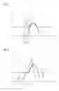
FIG. 1 shows an illustration of coil current, armature movement, and nozzle needle movement in the event of conventional actuation of a fuel injector with an idle stroke during ballistic operation; and
FIG. 2 shows an illustration of coil current, armature movement, and nozzle needle movement in the event of actuation of a fuel injector with an idle stroke during ballistic operation incorporating teachings of the present disclosure.
It should be noted that the embodiments described below are merely a limited selection of possible variant embodiments of the teachings herein.
DETAILED DESCRIPTION
Some embodiments include a method for actuating a fuel injector, which has a solenoid drive and a nozzle needle, for an internal combustion engine of a motor vehicle, wherein the solenoid drive has a solenoid and a movable armature, wherein the fuel injector has an idle stroke between the armature and the nozzle needle. An example method comprises the following: (a) applying a precharging current to the solenoid drive during a precharging phase in order to bring the movable armature into mechanical contact with the nozzle needle, and (b) applying a voltage pulse to the solenoid drive during a boost phase until the current intensity of the current flowing through the solenoid reaches a predetermined peak value. The scatter of the injection quantities in the case of fuel injectors with an idle stroke is considerably reduced or counteracted by moving the injector to a state without an idle stroke.
In this application, “boost phase” refers to a phase of actuation of a fuel injector in which a voltage (for example approximately 65 V) which is elevated (in comparison to the battery voltage which is typically 12 V for example) is applied to the fuel injector. The boost phase serves to create or initiate rapid opening of the fuel injector and is terminated by the current intensity of the current flowing through the solenoid reaching a predetermined peak value (also called peak current).
In some embodiments, the method begins with a precharging phase in which the movable armature of the fuel injector is brought into mechanical contact with the nozzle needle in the sense that the armature is moved from its inoperative position without a large or substantial pulse out of the idle stroke to the position in which the hydraulically active nozzle needle remains. In other words, the fuel injector is moved to the so-called OPP1 state during the precharging phase. In the process, the precharging current is preferably kept so low that the armature is gently placed against the nozzle needle and remains there for the time being. This can be performed, for example, by current regulation, wherein a suitably low coil voltage is alternately switched on and switched off.
In some embodiments, the precharging phase is followed by a boost phase. In a boost phase, an (elevated) voltage pulse is applied to the solenoid drive, this lasting until a predetermined peak value of the coil current is reached, following which the voltage is switched off, and therefore the current intensity can drop again. As a result, the fuel injector is at least partially opened and releases a certain injection quantity. Owing to the previously carried out precharging phase, the starting conditions for the opening process are well defined here and scatter of the injection quantity (between injection processes with one fuel injector and also between injection processes of different fuel injectors with the same injection parameters) will be very low or negligible.
In some embodiments, the predetermined peak value is such that the nozzle needle carries out a ballistic movement. In other words, the predetermined peak value is selected to be so low that the nozzle needle follows a parabolic path and does not stop at the top (against the pole piece). Therefore, the fuel injector is not completely open.
In some embodiments, the method further comprises once again applying the precharging current to the solenoid drive in order to keep the movable armature in mechanical contact with the nozzle needle. In such embodiments, the movable armature is moved back into the position achieved by the precharging phase here, so that a subsequent injection operation can take place under similar or identical starting conditions. In some embodiments, this includes suitable regulation which allows the current intensity to drop down to the precharging current and then allows said current intensity to remain at this value.
In some embodiments, the method further comprises applying a further voltage pulse to the solenoid drive during a further boost phase until the current intensity of the current flowing through the solenoid reaches a further predetermined peak value. In such embodiments, a further injection operation takes place, wherein scatter in the injection quantity is avoided in a similar way as in the case of the preceding injection operation.
In some embodiments, the further predetermined peak value is such that the nozzle needle carries out a further ballistic movement.
In some embodiments, the further predetermined peak value is equal to the predetermined peak value. Therefore, in this case, two substantially identical injection operations follow one another.
In some embodiments, the precharging current is such that substantially no movement of the nozzle needle takes place during the precharging phase. In other words, the precharging current is selected such that the armature is moved smoothly in the direction of the nozzle needle and gently stops and is braked there.
Some embodiments include an engine controller for a vehicle, which engine controller is designed for using a method as described above and/or one of the above exemplary embodiments. The engine controller renders it possible to achieve injection quantities with a very low degree of scatter in a simple manner by way of using the method according to the first aspect.
Some embodiments include a computer program which, when executed by a processor, carries out a method incorporating the teachings herein. Within this document, a computer program is equivalent to a program element, a computer program product, and/or a computer-readable medium which contains instructions for controlling a computer system, in order to coordinate the manner of operation of a system or of a method in a suitable manner, in order to achieve the effects associated with the methods described herein. The computer program can be implemented as a computer-readable instruction code in any suitable programming language, such as JAVA, C++ etc. for example. The computer program can be stored on a computer-readable storage medium (CD-ROM, DVD, Blu-ray disk, removable drive, volatile or non-volatile memory, integral memory/processor etc.). The instruction code can program a computer or other programmable devices, such as in particular a control unit for an engine of a motor vehicle, in such a way that the desired functions are executed. Furthermore, the computer program can be provided in a network such as, for example, the Internet, from which a user can download it as required. The teachings can be practiced both by means of a computer program, i.e. software, and also by means of one or more specific electrical circuits, i.e. as hardware or in any desired hybrid form, i.e. by means of software components and hardware components.
It should be noted that embodiments of the teachings herein have been described. In particular, some embodiments are described by way of method claims and other embodiments are described by way of apparatus claims. However, it becomes immediately clear to a person skilled in the art upon reading this application that, unless explicitly stated otherwise, in addition to a combination of features which are associated with one type of subject matter of the invention, any combination of features which are associated with different types of subjects is also possible.
FIG. 1 shows an illustration of coil current 11, armature movement 12, and nozzle needle movement 13 in the event of conventional actuation of a fuel injector with an idle stroke during ballistic operation. Specifically, FIG. 1 shows a current profile 11 (as a function of time t) which increases starting from a specific time until a peak value is reached. The duration of this boost phase is identified by Ti. Shortly after the boost phase begins, the armature moves upward and then substantially describes a parabolic movement, as is illustrated with reference to curve 12. The nozzle needle is moved only after a time period, identified by Th, starting from the beginning of the boost phase by way of the armature reaching the inoperative position A of the nozzle needle and carrying the nozzle needle with it. The nozzle needle then also describes a parabolic movement, as is illustrated with reference to curve 13. The completely open position of the fuel injector, which is identified by B, is not reached.
FIG. 2 shows an illustration of coil current 21, armature movement 22 and nozzle needle movement 23 in the event of actuation according to the invention of a fuel injector with an idle stroke during ballistic operation. Specifically, the actuation according to the invention begins with a precharging phase 24 in which the coil current 21 is regulated at a relatively low value which, however, suffices to move the armature 22 smoothly as far as the inoperative position of the nozzle needle A. This is followed by a boost phase Ti in which the current intensity 21 increases until the peak value (peak current) is reached.
After approximately half the duration of the boost phase Ti, the armature and nozzle needle, together, move along a parabolic movement curve. In the embodiment illustrated in FIG. 2, the coil current 21 returns to its starting value prior to the precharging phase (that is to say OA), so that the armature also returns to its starting position again. However, it should be mentioned that, in some embodiments, the coil current 21 returns only as far as the initially set precharging current, so that the armature remains in contact with the nozzle needle (position A) after the injection process and therefore a subsequent injection operation can be performed under similar conditions to that of the first injection operation.
LIST OF REFERENCE SYMBOLS
- 11 Current profile
- 12 Armature position
- 13 Nozzle needle position
- A Starting position of the nozzle needle
- B Topmost position of the nozzle needle
- t Time
- Ti Boost phase
- Th Time interval
- 21 Current profile
- 22 Armature position
- 23 Nozzle needle position
- 24 Precharging phase
- A Starting position of the nozzle needle
- B Topmost position of the nozzle needle
- t Time
- Ti Boost phase
Claims
What is claimed is:1. A method for actuating a fuel injector with a solenoid drive and a nozzle needle, wherein the solenoid drive has a solenoid and a movable armature and the fuel injector has an idle stroke between the armature and the nozzle needle, the method comprising:
applying a precharging current to the solenoid drive during a precharging phase to move the movable armature into mechanical contact with the nozzle needle; and
applying a voltage pulse to the solenoid drive during a boost phase until the current intensity of the current flowing through the solenoid reaches a predetermined peak value.
2. The method as claimed in claim 1, wherein the predetermined peak value is such that the nozzle needle carries out a ballistic movement.
3. The method as claimed in claim 1, further comprising applying the precharging current to the solenoid drive a second time to keep the movable armature in mechanical contact with the nozzle needle.
4. The method as claimed in claim 3, further comprising applying a further voltage pulse to the solenoid drive during a further boost phase until the current intensity of the current flowing through the solenoid reaches a second predetermined peak value.
5. The method as claimed in claim 4, wherein the second predetermined peak value is such that the nozzle needle carries out a further ballistic movement.
6. The method as claimed in claim 4, wherein the second predetermined peak value is equal to the predetermined peak value.
7. The method as claimed in claim 1, wherein the precharging current is such that substantially no movement of the nozzle needle takes place during the precharging phase.
8. An engine controller for a vehicle, the engine controller comprising:
a processor with access to a memory; and
a program stored in the memory comprising instructions executable by the processor to:
apply a precharging current to the solenoid drive during a precharging phase to move the movable armature into mechanical contact with the nozzle needle; and
apply a voltage pulse to the solenoid drive during a boost phase until the current intensity of the current flowing through the solenoid reaches a predetermined peak value.
9. A computer program which, when it is executed by a processor:
applies a precharging current to the solenoid drive during a precharging phase to move the movable armature into mechanical contact with the nozzle needle; and
applies a voltage pulse to the solenoid drive during a boost phase until the current intensity of the current flowing through the solenoid reaches a predetermined peak value.
Images & Drawings included:
Sources:
- United States Patent and Trademark Office - verify current appl. status at the USPTO↗
Recent applications in this class:
- » 20250283437 2025-09-11
FUEL INJECTOR DRIVE SYSTEM - » 20250163865 2025-05-22
VOLTAGE SUPPLY MODULE CONTROL FOR A FUEL INJECTED ENGINE - » 20250146451 2025-05-08
ELECTRONIC CONTROL DEVICE AND METHOD FOR CONTROLLING ELECTRONIC CONTROL DEVICE - » 20240151189 2024-05-09
Fuel injection control device - » 20240093655 2024-03-21
Method of determining closing time of needle valve of a fuel injector - » 20240044299 2024-02-08
Fuel injector control system and method - » 20240044298 2024-02-08
Fuel injector drive system - » 20230193844 2023-06-22
Optimized energy waveform for fuel injector trimming based on valve arrival time - » 20230184189 2023-06-15
Reduced energy waveform for energizing solenoid actuator in fuel injector valve - » 20230160353 2023-05-25
Device for detecting the state of a fuel injector
Recent applications for this Assignee:
- » 20250006057 2025-01-02
VEHICLE-EXIT ASSIST APPARATUS - » 20240312120 2024-09-19
METHOD AND DEVICE FOR PROVIDING A VISUALIZATION OF A VEHICLE, AND VEHICLE - » 20240295913 2024-09-05
ELECTRONIC DEVICE AND METHOD OF RESPONDING TO A TRIGGER TO WAKE UP - » 20240126118 2024-04-18
Display system and method for operating a display system - » 20240103589 2024-03-28
Frame for an electro-optical display and electro-optical display having a frame - » 20240103348 2024-03-28
Device for securing an optical device - » 20240103153 2024-03-28
Distance measuring system - » 20240100956 2024-03-28
Control unit circuit for a motor vehicle, motor vehicle and operating method for the control unit circuit - » 20240053161 2024-02-15
Method for predicting a velocity profile of a vehicle - » 20230358081 2023-11-09
Emergency access device for a vehicle openable leaf