Actuator for a medium voltage circuit breaker
US20190148093A1
2019-05-16
16/244,131
2019-01-10
✅ Patent granted
US 11,062,867 B2
2021-07-13
-
-
Mohamad A Musleh
Leydig, Voit & Mayer, Ltd.
2039-06-23
Abstract:
An actuator for a medium voltage circuit breaker or recloser includes: at least one movable contact with a contact stem, driven by an electromagnetic drive or a motor drive; and a spring, the spring being positioned in a kinematic chain between the drive and the at least one movable contact or contact stem. An arrangement of the at least one movable contact and the electromagnetic drive or motor drive is coupled to a detection unit for detecting a micromotion activation in order to register an actual movability and availability of the electromagnetic drive or motor drive of the at least one movable contact without changing an actual switch position itself.
Assignee:
- ABB SCHWEIZ AG 2,771 🇨🇭 Baden, Switzerland
Applicant:
Interested in similar patents?
Get notified when new applications in this technology area are published.
Classification:
H01H47/002 » CPC main
Circuit arrangements not adapted to a particular application of the relay and designed to obtain desired operating characteristics or to provide energising current Monitoring or fail-safe circuits
G01R31/3272 » CPC further
Arrangements for testing electric properties; Arrangements for locating electric faults; Arrangements for electrical testing characterised by what is being tested not provided for elsewhere; Testing of circuit interrupters, switches or circuit-breakers of high voltage or medium voltage devices Apparatus, systems or circuits therefor
H01H50/18 » CPC further
Details of electromagnetic relays; Magnetic circuit arrangements Movable parts of magnetic circuits, e.g. armature
H01H50/44 » CPC further
Details of electromagnetic relays Magnetic coils or windings
H01H50/56 » CPC further
Details of electromagnetic relays; Contact arrangements Contact spring sets
H01H50/64 IPC
Details of electromagnetic relays Driving arrangements between movable part of magnetic circuit and contact
H01H50/641 » CPC further
Details of electromagnetic relays; Driving arrangements between movable part of magnetic circuit and contact intermediate part performing a rectilinear movement
G01R31/327 IPC
Arrangements for testing electric properties; Arrangements for locating electric faults; Arrangements for electrical testing characterised by what is being tested not provided for elsewhere Testing of circuit interrupters, switches or circuit-breakers
H01H2235/01 » CPC further
Springs Spiral spring
H01H47/00 IPC
Circuit arrangements not adapted to a particular application of the relay and designed to obtain desired operating characteristics or to provide energising current
H01H71/10 » CPC further
Details of the protective switches or relays covered by groups - Operating or release mechanisms
H01H3/32 » CPC further
Mechanisms for operating contacts Driving mechanisms, i.e. for transmitting driving force to the contacts
H01H11/0062 » CPC further
Apparatus or processes specially adapted for the manufacture of electric switches Testing or measuring non-electrical properties of switches, e.g. contact velocity
H01F2007/185 » CPC further
Magnets; Electromagnets; Actuators including electromagnets with armatures; Circuit arrangements for obtaining desired operating characteristics, e.g. for slow operation, for sequential energisation of windings, for high-speed energisation of windings; Monitoring or fail-safe circuits with armature position measurement
H01H2003/268 » CPC further
Mechanisms for operating contacts; Power arrangements internal to the switch for operating the driving mechanism using dynamo-electric motor using a linear motor
H01F7/18 IPC
Magnets; Electromagnets; Actuators including electromagnets with armatures Circuit arrangements for obtaining desired operating characteristics, e.g. for slow operation, for sequential energisation of windings, for high-speed energisation of windings
H01H2009/566 » CPC further
Details of switching devices, not covered by groups - ; Circuit arrangements not adapted to a particular application of the switching device and for which no provision exists elsewhere for ensuring operation of the switch at a predetermined point in the ac cycle with self learning, e.g. measured delay is used in later actuations
H01H2047/009 » CPC further
Circuit arrangements not adapted to a particular application of the relay and designed to obtain desired operating characteristics or to provide energising current with self learning features, e.g. measuring the attracting current for a relay and memorising it
H01H2071/048 » CPC further
Details of the protective switches or relays covered by groups - ; Means for indicating condition of the switching device containing non-mechanical switch position sensor, e.g. HALL sensor
H01H11/00 IPC
Apparatus or processes specially adapted for the manufacture of electric switches
H01H9/56 IPC
Details of switching devices, not covered by groups - ; Circuit arrangements not adapted to a particular application of the switching device and for which no provision exists elsewhere for ensuring operation of the switch at a predetermined point in the ac cycle
H01H33/666 » CPC further
High-tension or heavy-current switches with arc-extinguishing or arc-preventing means; Switches wherein the means for extinguishing or preventing the arc do not include separate means for obtaining or increasing flow of arc-extinguishing fluid; Vacuum switches Operating arrangements
H01H71/04 IPC
Details of the protective switches or relays covered by groups - Means for indicating condition of the switching device
H01H3/26 IPC
Mechanisms for operating contacts; Power arrangements internal to the switch for operating the driving mechanism using dynamo-electric motor
Description
CROSS-REFERENCE TO PRIOR APPLICATION
This application is a continuation of International Patent Application No. PCT/EP2017/067634, filed on Jul. 12, 2017, which claims priority to European Patent Application No. EP 16179127.2, filed on Jul. 12, 2016. The entire disclosure of both applications is hereby incorporated by reference herein.
FIELD
The invention relates to an actuator for a medium voltage circuit breaker or recloser with at least one movable contact with a contact stem, driven by an electromagnetic drive or a motor drive, and a spring, wherein the spring is positioned in the kinematic chain between the drive and the movable contact or contact stem.
BACKGROUND
In general, for circuit breakers or reclosers, but especially for safety relevant applications, it is desirable to ensure that the circuit breaker or recloser would really operate when a signal command, either for closing or for opening, is given. What is being done usually with circuit breakers is a coil supervision—here, a small test current is running through the release coils to make sure, that there is no interruption in the current path (broken coil wire, broken cable, loose connector, . . . ). Then the operator can be sure, that a real command would energise the release coil of the drive of the circuit breaker or recloser, but there is no evidence that the drive would really move. There can be further failures between the release coil and the main shaft like loose screws or increased friction.
SUMMARY
In an embodiment, the present invention provides an actuator for a medium voltage circuit breaker or recloser, comprising: at least one movable contact with a contact stem, driven by an electromagnetic drive or a motor drive; and a spring, the spring being positioned in a kinematic chain between the drive and the at least one movable contact or contact stem, wherein an arrangement of the at least one movable contact and the electromagnetic drive or motor drive is coupled to a detection unit configured to detect a micromotion activation in order to register an actual movability and availability of the electromagnetic drive or motor drive of the at least one movable contact without changing an actual switch position itself.
BRIEF DESCRIPTION OF THE DRAWINGS
The present invention will be described in even greater detail below based on the exemplary figures. The invention is not limited to the exemplary embodiments. Other features and advantages of various embodiments of the present invention will become apparent by reading the following detailed description with reference to the attached drawings which illustrate the following:
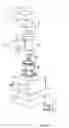
FIG. 1 shows a medium voltage circuit breaker or recloser pole in an open position;
FIG. 2 shows a medium voltage circuit breaker or recloser pole in a closed position;
FIG. 3 shows the general curves of coil current and drive position over time; and
FIG. 4 shows the curves of a strategy for a mircomotion in ON.
DETAILED DESCRIPTION
In an embodiment, an object of the invention is to get a qualified actual status signal about functional availability of the drive.
The invention is, that the arrangement of movable contact and movable contact drive is furthermore coupled to a detection unit for the detection of a micromotion activation and with means for feedback control of a micromotion activation, in order to register the actual movability and availability of the drive of the movable contact, without changing the actual switch position itself
The detection unit for the detection of a micromotion activation can be e.g. a sliding resistor or any other position measuring device. Alternatively, also an acceleration sensor can be used to detect the micromotion.
Alternatively, also an acoustic sensor can be used to detect the characteristic noise that occurs when the actuator comes back to its original position after the micromotion. Sensors like the acoustic sensor and the acceleration sensor do not have to be directly coupled to the drive or to the kinematic chain. The characteristic effect of the noise or of the vibration due to the micromotion can be detected anywhere inside the circuit breaker or recloser.
Alternatively, the back e.m.f of the actuator can be used instead of a separate sensor. The back e.m.f. is a voltage that is measurable at the terminals of the actuator coil. This voltage depends on the change of flux in the coil of the actuator due to the change of the current and the change of the position.
Many designs of circuit breakers and reclosers foresee one drive for more that one contact. Often there three contacts for three phase AC systems. The invention also works with and relates to these designs.
The basical idea is, to execute a small physical motion of the drive of the circuit breaker, to ensure that the drive is moveable and not blocked.
As the position of the circuit breaker—OFF (open) or ON (closed)—shall basically not be modified by this test, this motion has to be relatively small, compared to the nominal stroke of the drive. Because of that, the terminology “micromotion” is used. The motion of the drive shall not be more than a few mm away from the ON or OFF position.
When the circuit breaker or recloser is in OFF position, also the moveable contact of for example a vacuum interrupter will follow this small motion. The contact distance will be reduced accordingly for a short time, which will be in the range of a few milliseconds. As this motion will be small, compared to the nominal contact distance in OFF position, the insulating properties of the vacuum interrupter will not be significantly reduced. A small motion in the range of 1 mm can be compared with the backtravel motion, that can occur anyway in circuit breakers or reclosers at the end of the opening operation.
Due to lever ratios, mechanical loose and deflection, the travel of the drive and the travel of the contact or contacts can be different. Important is to limit the motion of the contact or contacts from the OFF position in a way to avoid dielectric problems. It is recommended to confirm with dielectric typetesting that the insulation levels for the circuit breaker or contactor are also valid when the contact or contacts are about 1 mm away from the OFF position.
When the circuit breaker or recloser is in ON position, the drive presses a contact spring against the movable contact of a vacuum interrupter and charges the contact spring by typically several mm. A small micromotion will therefore be compensated by an elongation of the contact spring, so that the movable contact will not move during the test. Explicitly, the contacts will not open during the test. The elongation of the contact spring or contact springs shall be distinctly smaller than the regular contact spring travel of the circuit breaker or recloser to ensure that the contact or contacts remain closed with sufficient contact force. Also here, a travel of about 1 mm is proposed.
In a further advantageous embodiment, the aforesaid feedback control of the micromotion activation is implemented in a signal device. By that, the functionality can be implemented also in retrofit, if the circuit breaker is already applied with the aforesaid contact spring.
In a further advantageous embodiment, the micromotion amplitude is round about 1 mm at the contact in OFF and at the contact spring in ON.
In a further advantageous embodiment, it is proposed, that between the stem of the movable contact and the pushrod is arranged an axial contact spring.
This was already functionally described in the aforesaid advantages.
In a further advantageous embodiment, it is proposed, that in the same effective axial direction of the pushrod is arranged an opening spring.
In a further advantageous embodiment, it is proposed, that a position sensor is mechanically linked to a movable part of the drive. So by that, the sensor placement is easier, than to place it near the contacts, or at the contact stem directly.
In a further advantageous embodiment, it is proposed, that an acceleration sensor is placed somewhere inside the circuit breaker or recloser.
In a further advantageous embodiment, it is proposed to evaluate the back e.m.f. of the actuator to detect the micromotion of the drive. This can be calculated in the signal device that drives the micromotion procedure at no extra costs. A separate sensor can then be saved.
A mathematical model of the actuator or motor consists mainly of a resistor, an inductor and a back e.m.f. voltage. This circuit is in general connected to a voltage source to drive a current. When the model is known, including the dependencies of the parameters mainly on the current and the position of the drive, the back e.m.f. can be detected by a comparison of the voltage source and the current and its derivatives with respect to time.
According to a method for operating an actuator for a medium voltage circuit breaker with at least one movable contact with a contact stem, driven by a contact electromagnetic drive or a motor drive, and a spring, wherein the spring is positioned in the kinematic chain between the drive and the movable contact or contact stem, the invention is, that in order to register the actual movability and availability of the drive of the movable contact, without changing the actual switch position itself, the drive is charged with a micro actuation signal.
A medium voltage circuit breaker or recloser pole, that is considered here, shall have the following structure, as shown in the FIGS. 1 (open) and 2 (closed) as an example:
In the OFF position of the circuit breaker or recloser, see FIG. 1, the concept of the micromotion can be realised relatively easy. The coil is energised in a similar way, as for a standard closing operation. As soon as the begin of the motion of the drive is detected, the current is controlled to zero and the drive will go back to the open position, driven by the opening spring(s).
In a further advantageous embodiment of the method, is, that for the micromotion in OFF, only the closing coil of the two-coil actuator is used, wherein at first the two coil actuator is energised with positive current, and then the coil will be energised with negative current to keep the movable part of the drive in the OFF position or to return it to the OFF position.
A further advantageous embodiment if, that for the micromotion in ON, only the closing coil of the two-coil actuator is used, the latch of the drive in ON is at first released by a small negative current in the closing coil, and then the latch is re-established by a strong positive current.
FIG. 3 shows the general curves of coil current and drive position over time. The current starts to increase from 0 to a certain value, e.g. by connection of the coil to a supply voltage. The position of the drive is the OFF position. In case the current reaches a certain predefined level before motion starts, the current can be kept constant, e.g. using a current controller with pulse width modulation (PWM). After a certain time, the drive will start to move from OFF towards the ON position. The current is now reduced e.g. by reversing the driving voltage. Due to the inertia of the motion and the still existing driving force the drive will continue its motion towards the ON position for some time, but as current decreases, and supported by the force of the opening spring(s), the drive will return to the OFF position.
The micromotion cycle in OFF is now completed; there is evidence that the drive is movable.
The general design of a medium voltage circuit breaker or recloser with vacuum interrupters includes relatively strong contact springs 6 between the drive and the movable contact of the vacuum interrupter. These springs support the opening operation in the beginning. Further, additional opening springs 8 can be installed to support the entire opening operation. The magnetic latching force of the actuator will however become strongly lower as soon as a motion occurs, i.e. when the moveable part of the drive 11 moves away from the fixed part of the drive 9. The risk for the mircomotion in ON is, that these springs can bring the drive in a situation, where the opening forces (contact springs plus opening springs) are higher than the closing force of the magnetic actuator. The result could be, that the motion is larger than desired, it can not be limited to be small. Therefore, the strategy for a mircomotion in ON can be different.
FIG. 4 shows the curves of this different strategy. The current is negative in the first period, as a negative current is used in magnetic actuators with one coil to reduce the magnetic holding force and so to initiate the opening operation, that is then mainly driven by the contact spring and the opening spring. Depending on the actual forces of all involved parts of the drive it can be that the motion of the drive is not a real micromotion, it could be larger than the defined target, e.g. larger than 1 mm. To avoid this large motion the proposed strategy is to reverse the direction of current before the motion is detectable. This will generate sufficient latching force to make sure that the motion is not larger than the defined target.
It can now be the case that the reverse of the current is so early, that a motion does not occur at all. In that case, the controller shall repeat the test with a slightly later reverse of the current or with a slightly stronger driving voltage or current. The procedure can be repeated until a micromotion could be noticed or until a defined current- or drive voltage- or feeding time-threshold was reached that indicates that the drive has a failure if it does not move with this threshold current or threshold voltage of threshold feeding time.
This principle can also be used for the micromotion in OFF to realise smaller motions. Depending on the actual design of the magnetic drive it can also be necessary to use this principle for mircomotion in OFF.
The test with the micromotion shall be repeated on a regular basis, e.g. once an hour or once a day.
These principles can also be used for two-coil actuators, as shown e.g. in EP0721650. Instead of positive and negative currents in one coil, the current in the closing coil and the current in the opening coil can be used to obtain the desired motion of the drive.
In another advantageous embodiment, for the micromotion in OFF, only the closing coil of the two-coil actuator is used. It is at first energised with positive current. Then the coil shall be energised with negative current to keep the movable part of the drive in the OFF position or to return it to the OFF position.
In another advantageous embodiment, for the micromotion in ON, only the closing coil of the two-coil actuator is used. The latch of the drive in ON is at first released by a small negative current in the closing coil. Then the latch is re-established by a strong positive current. This is quite similar to the procedure with one-coil actuators.
While the invention has been illustrated and described in detail in the drawings and foregoing description, such illustration and description are to be considered illustrative or exemplary and not restrictive. It will be understood that changes and modifications may be made by those of ordinary skill within the scope of the following claims. In particular, the present invention covers further embodiments with any combination of features from different embodiments described above and below. Additionally, statements made herein characterizing the invention refer to an embodiment of the invention and not necessarily all embodiments.
The terms used in the claims should be construed to have the broadest reasonable interpretation consistent with the foregoing description. For example, the use of the article “a” or “the” in introducing an element should not be interpreted as being exclusive of a plurality of elements. Likewise, the recitation of “or” should be interpreted as being inclusive, such that the recitation of “A or B” is not exclusive of “A and B,” unless it is clear from the context or the foregoing description that only one of A and B is intended. Further, the recitation of “at least one of A, B and C” should be interpreted as one or more of a group of elements consisting of A, B and C, and should not be interpreted as requiring at least one of each of the listed elements A, B and C, regardless of whether A, B and C are related as categories or otherwise. Moreover, the recitation of “A, B and/or C” or “at least one of A, B or C” should be interpreted as including any singular entity from the listed elements, e.g., A, any subset from the listed elements, e.g., A and B, or the entire list of elements A, B and C.
NUMBERING
1 Upper electrical terminal
2 Fixed switching contact
3 Movable switching contact
4 Electrical contact, sliding or flexible conductor
5 Lower electrical terminal
6 Contact spring
7 Pushrod
8 Opening spring; upper end is fixed
9 Fixed part of drive
10 Coil of drive
11 Movable part of drive
12 Position sensor
Claims
What is claimed is:1. An actuator for a medium voltage circuit breaker or recloser, comprising:
at least one movable contact with a contact stem, driven by an electromagnetic drive or a motor drive; and
a spring, the spring being positioned in a kinematic chain between the drive and the at least one movable contact or contact stem,
wherein an arrangement of the at least one movable contact and the electromagnetic drive or motor drive is coupled to a detection unit configured to detect a micromotion activation in order to register an actual movability and availability of the electromagnetic drive or motor drive of the at least one movable contact without changing an actual switch position itself
2. The actuator according to claim 1, wherein the detection unit and the feedback control of the micromotion activation are implemented in a signal device.
3. The actuator according to claim 1, wherein a micromotion amplitude is round about 1 mm at the at least one movable contact in OFF and at the contact spring in ON.
4. The actuator according to claim 1, wherein an axial contact spring is arranged between the stem of the at least one movable contact and a pushrod.
5. The actuator according to claim 4, wherein an opening spring is arranged in a same effective axial direction of the pushrod.
6. The actuator according to claim 1, further comprising a positions sensor mechanically linked to a movable part of the electromagnetic drive or motor drive, the positions sensor being configured to detect a micromotion.
7. The actuator according to claim 1, further comprising an acceleration sensor coupled to the electromagnetic drive or motor drive by placing the acceleration sensor inside of or closely to the circuit breaker or recloser as a means for the detection of a micromotion.
8. The actuator according to claim 1, wherein a back e.m.f of the electromagnetic drive or motor drive is evaluated to detect the micromotion.
9. A method for operating an actuator for a medium voltage circuit breaker with at least one movable contact with a contact stem, driven by a contact electromagnetic drive or a motor drive, and a spring, wherein the spring is positioned in a kinematic chain between the drive and the movable contact or contact stem, the method comprising:
charging the electromagnetic drive or a motor drive with an micro actuation signal in order to register an actual movability and availability of the electromagnetic drive or a motor drive of the at least one movable contact, without changing an actual switch position itself
10. The method according to claim 9, wherein for a micromotion in OFF, only a closing coil of a two-coil actuator is used, and
wherein at first the two coil actuator is energised with positive current, and then the coil is energised with negative current to keep the at least one movable contact of the electromagnetic drive or the motor drive in the OFF position or to return it to the OFF position.
11. The method according to claim 9, wherein for the micromotion in ON, only a closing coil of the two-coil actuator is used, a latch of the electromagnetic drive or a motor drive in ON is at first released by a small negative current in the closing coil, and then the latch is re-established by a strong positive current.
Images & Drawings included:


Sources:
- United States Patent and Trademark Office - verify current appl. status at the USPTO↗
Similar patent applications:
- » 20120286905
Bistable magnetic actuator for a medium voltage circuit breaker - » 20150170857
ELECTROMAGNETIC ACTUATOR FOR A MEDIUM VOLTAGE VACUUM CIRCUIT BREAKER - » 20230352255
Control scheme for the operation of an electric motor actuator for a medium to high voltage circuit breaker - » 20150300510
Hydraulic valve for preventing leakage in an actuator for activating a high- or medium-voltage circuit breaker
Recent applications in this class:
- » 20250259812 2025-08-14
METHOD FOR ACTUATING AN ELECTROMECHANICAL SWITCHING ELEMENT - » 20250218713 2025-07-03
POWER SUPPLY CONTROL DEVICE, POWER SUPPLY CONTROL METHOD, AND COMPUTER PROGRAM - » 20250210291 2025-06-26
IN-VEHICLE CONTROL DEVICE - » 20250118515 2025-04-10
CONTACTOR AND CONTROL METHOD THEREOF - » 20250118514 2025-04-10
APPARATUS AND METHOD FOR MONITORING STATUS OF RELAY CIRCUIT - » 20250029801 2025-01-23
SYSTEMS AND METHODS FOR AUTOMATICALLY CONFIGURING POINT-ON-WAVE SETTINGS IN A RELAY DEVICE - » 20240420906 2024-12-19
ELECTROMECHANICAL RELAY AND MONITORING SWITCH FOR AN ELECTROMECHANICAL RELAY - » 20240395486 2024-11-28
ENHANCED SWITCHGEAR MONITORING AND DIAGNOSTICS IN A PROTECTION RELAY - » 20240249901 2024-07-25
OVERCURRENT PROTECTION - » 20240234060 2024-07-11
Contact monitoring apparatus for a three-pole changeover contact
Recent applications for this Assignee:
- » 20250293491 2025-09-18
Switchgear Tank - » 20250291340 2025-09-18
Generating Control Code for an Industrial Plant - » 20250291337 2025-09-18
System and a Method for Mitigating Data Drift in an Industrial Plant - » 20250291331 2025-09-18
System and Method for Anomaly Remediation in an Industrial Process - » 20250290832 2025-09-18
Fault State Detection Apparatus - » 20250290315 2025-09-18
LAYERED PANEL AND METHOD OF CONSTRUCTION THEREOF - » 20250289662 2025-09-18
Vehicle System and Vehicles Therefore - » 20250285824 2025-09-11
Tripping Mechanism - » 20250284268 2025-09-11
Automatic Control Code Generation for Industrial Assets - » 20250283943 2025-09-11
Method of Synchronization of Sensors, Computer Program Product and Computer-Readable Storage Medium