Electrical connections for wearables and other articles
US20190148900A1
2019-05-16
16/244,601
2019-01-10
✅ Patent granted
US 10,892,588 B2
2021-01-12
-
-
William H. Mayo, III | Krystal Robinson
2039-04-21
Abstract:
This invention is related to electrical connections in wearable garments and other articles that enable the transfer of electrical signals or electrical power from one site in the garment or article to another site on the garment or article by the use of an electrical conductor printed along the length of a sewable substrate which bridges the two sites.
Inventors:
- Mark Allan Lamontia 42 🇺🇸 Landenberg, PA, United States
- Joseph James Duffy 5 🇺🇸 Newark, DE, United States
Assignee:
- DUPONT ELECTRONICS, INC. 56 🇺🇸 Wilmington, DE, United States
Applicant:
Interested in similar patents?
Get notified when new applications in this technology area are published.
Classification:
H01R12/77 IPC
Structural associations of a plurality of mutually-insulated electrical connecting elements, specially adapted for printed circuits, e.g. printed circuit boards [PCBs], flat or ribbon cables, or like generally planar structures, e.g. terminal strips, terminal blocks; Coupling devices specially adapted for printed circuits, flat or ribbon cables, or like generally planar structures; Terminals specially adapted for contact with, or insertion into, printed circuits, flat or ribbon cables, or like generally planar structures; Coupling devices for flexible printed circuits, flat or ribbon cables or like structures
A61B5/00 IPC
Measuring for diagnostic purposes ; Identification of persons
A61B5/02438 » CPC further
Measuring for diagnostic purposes ; Identification of persons; Detecting, measuring or recording pulse, heart rate, blood pressure or blood flow; Combined pulse/heart-rate/blood pressure determination; Evaluating a cardiovascular condition not otherwise provided for, e.g. using combinations of techniques provided for in this group with electrocardiography or electroauscultation; Heart catheters for measuring blood pressure; Detecting, measuring or recording pulse rate or heart rate with portable devices, e.g. worn by the patient
H01L23/5387 » CPC further
Details of semiconductor or other solid state devices; Arrangements for conducting electric current within the device in operation from one component to another, i.e. interconnections, e.g. wires, lead frames the interconnection structure between a plurality of semiconductor chips being formed on, or in, insulating substrates Flexible insulating substrates
A41B1/08 » CPC further
Shirts Details
A61B5/6805 » CPC further
Measuring for diagnostic purposes ; Identification of persons; Arrangements of detecting, measuring or recording means, e.g. sensors, in relation to patient specially adapted to be attached to or worn on the body surface; Sensor mounted on worn items; Garments; Clothes Vests
H05K1/03 IPC
Printed circuits; Details Use of materials for the substrate
H05K1/03 IPC
Printed circuits; Details Use of materials for the substrate
H01R12/771 » CPC further
Structural associations of a plurality of mutually-insulated electrical connecting elements, specially adapted for printed circuits, e.g. printed circuit boards [PCBs], flat or ribbon cables, or like generally planar structures, e.g. terminal strips, terminal blocks; Coupling devices specially adapted for printed circuits, flat or ribbon cables, or like generally planar structures; Terminals specially adapted for contact with, or insertion into, printed circuits, flat or ribbon cables, or like generally planar structures; Coupling devices for flexible printed circuits, flat or ribbon cables or like structures Details
H05K1/038 » CPC further
Printed circuits; Details; Use of materials for the substrate Textiles
H05K1/038 » CPC further
Printed circuits; Details; Use of materials for the substrate Textiles
A41B2300/20 » CPC further
Details of shirts, underwear, baby linen or handkerchiefs not provided for in other groups of this subclass Inserts
A41B2300/35 » CPC further
Details of shirts, underwear, baby linen or handkerchiefs not provided for in other groups of this subclass Seams
A41D1/005 » CPC further
Garments adapted to accommodate electronic equipment with embedded cable or connector
A41D2300/50 » CPC further
Details of garments Seams
H01R33/94 » CPC main
Coupling devices specially adapted for supporting apparatus and having one part acting as a holder providing support and electrical connection via a counterpart which is structurally associated with the apparatus, e.g. lamp holders; Separate parts thereof Holders formed as intermediate parts for linking a counter-part to a coupling part
H01L23/538 IPC
Details of semiconductor or other solid state devices; Arrangements for conducting electric current within the device in operation from one component to another, i.e. interconnections, e.g. wires, lead frames the interconnection structure between a plurality of semiconductor chips being formed on, or in, insulating substrates
A61B5/024 IPC
Measuring for diagnostic purposes ; Identification of persons; Detecting, measuring or recording pulse, heart rate, blood pressure or blood flow; Combined pulse/heart-rate/blood pressure determination; Evaluating a cardiovascular condition not otherwise provided for, e.g. using combinations of techniques provided for in this group with electrocardiography or electroauscultation; Heart catheters for measuring blood pressure Detecting, measuring or recording pulse rate or heart rate
H01B1/20 » CPC further
Conductors or conductive bodies characterised by the conductive materials; Selection of materials as conductors Conductive material dispersed in non-conductive organic material
A41D1/00 IPC
Garments
H01R12/65 » CPC further
Structural associations of a plurality of mutually-insulated electrical connecting elements, specially adapted for printed circuits, e.g. printed circuit boards [PCBs], flat or ribbon cables, or like generally planar structures, e.g. terminal strips, terminal blocks; Coupling devices specially adapted for printed circuits, flat or ribbon cables, or like generally planar structures; Terminals specially adapted for contact with, or insertion into, printed circuits, flat or ribbon cables, or like generally planar structures; Fixed connections for flexible printed circuits, flat or ribbon cables or like structures characterised by the terminal
A41D2300/20 » CPC further
Details of garments Inserts
Description
FIELD OF THE INVENTION
This invention is directed to electrical connections in wearable garments and other articles to enable the transfer of electrical signals from one part of the garment to another part.
BACKGROUND OF THE INVENTION
There is increasing interest in incorporating electrical circuits in wearable garments to monitor physiological aspects of the wearer. Examples of such measurements include heart rate, electrocardiography, skin or core temperature and parameters of bodily fluids. These electrical circuits are also useful for adding energy to power devices such as heaters to increase comfort or for adding information to contained devices. These electrical circuits are also useful for articles, e.g., sleeping bags and blankets, requiring stretchable circuits. Additional uses for circuits in wearable garments and other articles are also contemplated. There is a need for methods of transferring electrical signals from one part of the wearable garment or article to another part and therefore a need for making electrical connections between different parts of the garment or article. These connections must be maintained as the garment or article is stretched and exposed to multiple wash and dry cycles.
SUMMARY OF THE INVENTION
This invention provides electrical connections in wearable garments and other articles to enable the transfer of electrical signals or electrical power from different sites of the garment or the articles.
The invention provides an electrical connection from an electrical conductor inside a wearable garment to a designated site on the outer side of the garment, the connection comprising:
-
- an electrical conductor printed along the length of a bridging sewable substrate, wherein one end of the bridging sewable substrate is placed such that the printed conductor at that end of the bridging sewable substrate is in contact with the electrical conductor inside the garment, wherein one or more stitches with non-conductive thread are sewn through the bridging sewable substrate with each stitch encompassing the portions of the two electrical conductors that are in contact, thereby providing the compression necessary to form an electrical connection between the two conductors and wherein the other end of the bridging sewable substrate is placed at the designated site.
In one such embodiment, the end of the bridging sewable substrate at the designated site has been passed through an opening in the garment that provides access to the designated site so that the bridging sewable substrate overlaps the outer side of the garment as it approaches the designated site.
In another such embodiment, the end of the bridging sewable substrate at the designated site has been passed through a seam in the garment that provides access to the designated site so that the bridging sewable substrate overlaps the outer side of the garment as it approaches the designated site.
In still another such embodiment, the end of the bridging sewable substrate at the designated site has been folded around the edge of the garment, i.e., the end of a sleeve or a collar or the top or bottom of the garment, so that the bridging sewable substrate overlaps the outer side of the garment as it approaches the designated site.
In any of the above embodiments, the electrical conductor inside the garment is a wire.
In any of the above embodiments, the electrical conductor inside the garment is an electrical conductor printed on a sewable substrate and the one or more stitches are sewn through both sewable substrates
The invention also provides an electrical connection from a first site on an article to a second site on the article.
BRIEF DESCRIPTION OF THE FIGURES
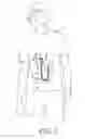
FIG. 1 illustrates an electrical connection from an electrical conductor inside a garment to a designated site on the outer side of the garment wherein the bridging sewable substrate with the printed electrical conductor along its length has one end in contact with the conductor inside the garment and the other end at the designated site and the bridging sewable substrate passes through an opening in the garment to the designated site on the outer side of the garment.
FIG. 2 is a cross-sectional view of an electrical connection from an electrical conductor inside the garment to a designated site in a pocket on the outer side of the garment wherein the bridging sewable substrate with the printed electrical conductor along its length has one end in contact with the conductor inside the garment and the other end at the designated site and the bridging sewable substrate passes through an opening in the garment to the designated site in the pocket on the outer side of the garment.
FIG. 3 is a cross-sectional view of an electrical connection from an electrical conductor inside the garment to a designated site in a flap on the outer side of the garment wherein the bridging sewable substrate with the printed electrical conductor along its length has one end in contact with the conductor inside the garment and the other end at the designated site and the bridging sewable substrate passes through an opening in the garment to the designated site in the flap on the outer side of the garment.
FIG. 4 is a cross-sectional view of an electrical connection from an electrical conductor inside the garment to a designated site in a folded flap on the outer side of the garment wherein the bridging sewable substrate with the printed electrical conductor along its length has one end in contact with the conductor inside the garment and the other end at the designated site and the bridging sewable substrate passes through an opening in the garment to the designated site in the folded flap on the outer side of the garment.
DETAILED DESCRIPTION OF THE INVENTION
The invention relates to electrical connections in wearable garments or other articles to enable the transfer of electrical signals or power from one part of a garment or article to another.
This invention provides an electrical connection from an electrical conductor inside a wearable garment to a designated site on the outer side of the garment, the connection comprising an electrical conductor printed along the length of a bridging sewable substrate, wherein one end of the bridging sewable substrate is placed such that the printed conductor at that end of the bridging sewable substrate is in contact with the electrical conductor inside the garment, wherein one or more stitches with non-conductive thread are sewn through the bridging sewable substrate with each stitch encompassing the portions of the two electrical conductors that are in contact, thereby providing the compression necessary to form an electrical connection between the two conductors and wherein the other end of the bridging sewable substrate is placed at the designated site. In some embodiments the designated site is in a pocket of the garment or in a flap or folded flap on the garment. The garment in these embodiments can be a single layer or a multi-layer garment. In some embodiments the electrical conductor inside the garment may be a wire. In other embodiments. the electrical conductor inside the garment is an electrical conductor printed on a sewable substrate and the one or more stitches are sewn through both sewable substrates.
A wearable garment has an inner surface or side nearest to the body of the wearer and an outer surface or side farthest from the body of the wearer. As used herein, “an electrical conductor inside the garment” refers to an electrical conductor in the region between the body of the wearer and the inner surface of the garment. The electrical conductor may be attached to the body of the wearer or be attached to the inner surface of the garment or be attached to an electrical circuit in the region between the body of the wearer and the inner surface of the garment.
As used herein, “bridging substrate” refers to the substrate with the electrical conductor printed along its length, the substrate bridging the gap between a first site and a second site or between the electrical conductor inside the garment and the designated site on the outer side of the garment.
As used herein, “flap” refers to a projecting or hanging piece attached to the outer side of the garment. The flap may be folded to form a “folded flap” that provides an enclosure for the designated site and any attachments to it.
As used herein, “wearable garment” or “wearable” refers to any article that may be worn by a person and includes a shirt, a sweater, a coat or jacket, a pair of slacks, socks, and footwear.
As used herein, “lamination” refers to the bonding of two layers together. This can be accomplished by the typical process of heat and compressing the layers but also by other means such as the use of an adhesive or gluing.
Some of the above embodiments will be discussed with reference to the Figures. In the Figures, prime numbers are used to indicated the portions of the bridging sewable substrate and the electrical conductor printed along its length that lie outside the garment and un-primed numbers are used to indicated the portions of the bridging sewable substrate and the electrical conductor printed along its length that lie inside the garment.
FIG. 1 illustrates an electrical connection from an electrical conductor inside a garment to a designated site on the outer side of the garment wherein the bridging sewable substrate with the printed electrical conductor along its length has one end in contact with the conductor inside the garment and the other end at the designated site and the bridging sewable substrate passes through an opening in the garment to the designated site on the outer side of the garment. The garment 1 has an opening 3 in the garment 1. There is the electrical conductor 4 inside the garment and the designated site 5 on the outer side of the garment. Inside the garment, the bridging sewable substrate 6 with the electrical conductor 7 printed along its length is shown beginning at the electrical conductor 4 and proceeding to the opening 3. The bridging sewable substrate with the electrical conductor printed along its length passes through the opening 3. On the outer side of the garment, the bridging sewable substrate 6′ with the electrical conductor 7′ printed along its length terminates at the designated site 5. Two stitches of non-conductive thread 8 are sewn through the bridging sewable substrate 6 with each stitch encompassing the portions of the two electrical conductors 4 and 7 that are in contact.
FIG. 2 is a cross-sectional view through plane AB of FIG. 1 of an electrical connection from an electrical conductor inside a garment to a designated site in a pocket on the outer side of the garment wherein the bridging sewable substrate with the printed electrical conductor along its length has one end at the electrical conductor inside the garment and the other end at the designated site and the bridging sewable substrate passes through an opening in the garment to the designated site in the pocket on the outside of the garment. The garment 1 has a pocket 2 and an opening 3 in the garment 1. There is the electrical conductor 4 inside the garment and the designated site 5 on the outer side of the garment in the pocket 2. Inside the garment, the bridging sewable substrate 6 with the electrical conductor 7 printed along its length is shown beginning at the electrical conductor 4 and proceeding to the opening 3. The bridging sewable substrate with the electrical conductor printed along its length passes through the opening 3. On the outer side of the garment, the bridging sewable substrate 6′ with the electrical conductor 7′ printed along its length terminates at the designated site 5 in the pocket 2. Two stitches of non-conductive thread 8 are sewn through the bridging sewable substrate 6 with each stitch encompassing the portions of the two electrical conductors 4 and 7 that are in contact.
FIG. 3 is a cross-sectional view through plane AB of FIG. 1 of an electrical connection from an electrical conductor inside a garment to a designated site in a flap on the outer side of the garment wherein the bridging sewable substrate with the printed electrical conductor along its length has one end at the electrical conductor inside the garment and the other end at the designated site and the bridging sewable substrate passes through an opening in the garment to the designated site in the flap on the outside of the garment. The garment 1 has a flap 2 and an opening 3 in the garment 1. There is the electrical conductor 4 inside the garment and the designated site 5 on the outer side of the garment in the flap 2. Inside the garment, the bridging sewable substrate 6 with the electrical conductor 7 printed along its length is shown beginning at the electrical conductor 4 and proceeding to the opening 3. The bridging sewable substrate with the electrical conductor printed along its length passes through the opening 3. On the outer side of the garment, the bridging sewable substrate 6′ with the electrical conductor 7′ printed along its length terminates at the designated site 5 in the flap 2. Two stitches of non-conductive thread 8 are sewn through the bridging sewable substrate 6 with each stitch encompassing the portions of the two electrical conductors 4 and 7 that are in contact.
FIG. 4 is a cross-sectional view through plane AB of FIG. 1 of an electrical conductor inside the garment to a designated site in a folded flap on the outer side of the garment wherein the bridging sewable substrate with the printed electrical conductor along its length has one end at the electrical conductor inside the garment and the other end at the designated site and the bridging sewable substrate passes through an opening in the garment to the designated site in the folded flap on the outside of the garment. The garment 1 has a folded flap 2 and an opening 3 in the garment 1. There is the electrical conductor 4 inside the garment and the designated site 5 on the outer side of the garment in the folded flap 2. Inside the garment, the bridging sewable substrate 6 with the electrical conductor 7 printed along its length is shown beginning at the electrical conductor 4 and proceeding to the opening 3. The bridging sewable substrate with the electrical conductor printed along its length passes through the opening 3. On the outer side of the garment, the bridging sewable substrate 6′ with the electrical conductor 7′ printed along its length terminates at the designated site 5 in the folded flap 2. Two stitches of non-conductive thread 8 are sewn through the bridging sewable substrate 6 with each stitch encompassing the portions of the two electrical conductors 4 and 7 that are in contact.
Embodiments with the bridging substrate passing through a seam would be similar to those illustrated in FIGS. 1, 2, 3 and 4 with a seam replacing the opening 3.
As shown in FIG. 1, the bridging substrate 6 and 6′ is adjacent to the garment 1 both inside and outside the garment and the electrical conductor 7 and 7′ is exposed making connections at the electrical conductor 4 inside the garment 1 and the designated site 5 outside the garment 1 convenient. The bridging substrate can be reversed so that the electrical conductor 7 and 7′ is adjacent to the garment 1 both inside and outside the garment thereby providing the electrical conductor 7 and 7′ protection from abrasion. For embodiments in which the bridging substrate with the printed electrical conductor consists of two separate pieces of substrate each with an electrical conductor printed along its length, the two substrates can be placed so that the bridging substrate is adjacent to the garment on one side of the garment and the electrical conductor is adjacent to the garment on the other side. Similar reversals or combinations of two separate pieces of substrate are applicable to all embodiments.
In any of the above embodiments, the bridging substrate may comprise thermoplastic or thermoset films. Examples of typical substrates are thermoplastic urethane (TPU) such as Bemis ST-604 available from Bemis Associates, Inc., Shirley, Mass., thermoplastic polyester such as DuPont™ Hytrel® available from the DuPont Co., Wilmington, Del., thermoplastic polyethylene terephthalate (PET) and DuPont™ Kapton® polyimide available from the DuPont Co., Wilmington, Del.
In any of the above embodiments, the electrical conductor printed along the length of the bridging sewable substrate may be formed from a polymer thick film conductor composition.
In any of the above embodiments, the electrical conductor printed along the length of the bridging sewable substrate may be formed from a polymer thick film silver composition.
In any of the above embodiments, the electrical connection may further comprise one or more additional electrical conductors printed along the length of the bridging sewable substrate.
In any of the above embodiments, the bridging sewable substrate with the printed electrical conductor may consist of two or more separate pieces of sewable substrate each with an electrical conductor printed along its length and wherein the printed conductors of neighboring pieces of sewable substrate are placed in contact and the electrical connection of the printed electrical conductors on the two or more pieces of substrate is achieved by means of:
-
- a) stitches with non-conductive thread, wherein each stitch is sewn through the neighboring sewable substrates and wherein each pair of contacted conductors is encompassed by at least one stitch, thereby providing the compression necessary to form an electrical connection of each pair; or
- b) lamination of two neighboring pieces of substrate; or
- c) fasteners compressing the two neighboring pieces of substrate together.
Claims
What is claimed is:1. An electrical connection from an electrical conductor inside a wearable garment to a designated site on the outer side of the garment, the connection comprising:
an electrical conductor printed along the length of a bridging sewable substrate, wherein one end of the bridging sewable substrate is placed such that the printed conductor at that end of the bridging sewable substrate is in contact with the electrical conductor inside the garment, wherein one or more stitches with non-conductive thread are sewn through the bridging sewable substrate with each stitch encompassing the portions of the two electrical conductors that are in contact, thereby providing the compression necessary to form an electrical connection between the two conductors and wherein the other end of the bridging sewable substrate is placed at the designated site.
2. The electrical connection of claim 1, wherein the end of the bridging sewable substrate at the designated site has been passed through an opening in the garment that provides access to the designated site so that the bridging sewable substrate overlaps the outer side of the garment as it approaches the designated site.
3. The electrical connection of claim 1, wherein the end of the bridging sewable substrate at the designated site has been passed through a seam in the garment that provides access to the designated site so that the bridging sewable substrate overlaps the outer side of the garment as it approaches the designated site.
4. The electrical connection of claim 1, wherein the end of the bridging sewable substrate at the designated site has been folded around an edge of the garment so that the bridging sewable substrate overlaps the outer side of the garment as it approaches the designated site.
5. The electrical connection of claim 1, wherein the electrical conductor inside the garment is a wire.
6. The electrical connection of claim 1, wherein the electrical conductor inside the garment is an electrical conductor printed on a sewable substrate and the one or more stitches are sewn through both sewable substrates.
7. The electrical connection of claim 1, wherein the designated site is in a pocket of the garment.
8. The electrical connection of claim 1, wherein the designated site is in a flap or a folded flap on the garment.
9. The electrical connection of claim 1, wherein the wearable garment is a single layer garment.
10. The electrical connection of claim 1, wherein the wearable garment is a multi-layer garment.
11. The electrical connection of claim 1, the bridging sewable substrate comprising thermoplastic urethane.
12. The electrical connection of claim 1, wherein the electrical conductor printed along the length of the bridging sewable substrate is formed from a polymer thick film conductor composition.
13. The electrical connection of claim 12, wherein the polymer thick film conductor composition is a polymer thick film silver composition.
14. The electrical connection of claim 1, the electrical connection further comprising one or more additional electrical conductors printed along the length of the bridging sewable substrate.
15. The electrical connection of claim 1, wherein the bridging sewable substrate with the printed electrical conductor consists of two or more separate pieces of sewable substrate each with an electrical conductor printed along its length and wherein the printed conductors of neighboring pieces of substrate are placed in contact and the electrical connection of the printed electrical conductors on the two or more pieces of substrate is achieved by means of:
a) stitches with non-conductive thread, wherein each stitch is sewn through the neighboring sewable substrates and wherein each pair of contacted conductors is encompassed by at least one stitch, thereby providing the compression necessary to form an electrical connection of each pair; or
b) lamination of two neighboring pieces of substrate; or
c) fasteners compressing the two neighboring pieces of substrate together.
16. An electrical connection from a first site on an article to a second site on the article, the connection comprising:
an electrical conductor printed along the length of a bridging sewable substrate, wherein one end of the bridging sewable substrate is placed such that the printed conductor at that end of the bridging sewable substrate is in contact with an electrical conductor at the first site, wherein one or more stitches with non-conductive thread are sewn through the bridging sewable substrate with each stitch encompassing the portions of the two electrical conductors that are in contact, thereby providing the compression necessary to form an electrical connection between the two conductors and wherein the other end of the bridging sewable substrate is placed at the second site.
Images & Drawings included:


Sources:
- United States Patent and Trademark Office - verify current appl. status at the USPTO↗
Similar patent applications:
Recent applications in this class:
- » 20250226632 2025-07-10
EXTENSION LAMP SOCKET - » 20250202178 2025-06-19
MODULAR POWER DISTRIBUTION SYSTEM - » 20250149840 2025-05-08
QUICK-COUPLING ELECTRICAL FIXTURE ASSEMBLY - » 20240258755 2024-08-01
STACKABLE DOCKING STATION - » 20240186758 2024-06-06
Combination outlet and power distribution unit incorporating the same - » 20240079835 2024-03-07
DATA SIGNAL TRANSMISSION CONNECTOR - » 20240006834 2024-01-04
UNIVERSAL MOBILE DEVICE MOUNT - » 20230155335 2023-05-18
Light Bulb and Power Adapter Combination Having an Edison Screw - » 20230134209 2023-05-04
Bulb adaptor - » 20230128960 2023-04-27
Combination outlet and power distribution unit incorporating the same
Recent applications for this Assignee:
- » 20240189466 2024-06-13
SELF-SANITIZING STRUCTURE FOR AUTOMATICALLY NEUTRALIZING INFECTIOUS AGENTS ON THE STRUCTURE'S COMMONLY TOUCHED SURFACES - » 20230279262 2023-09-07
Polymer compositions and coating solutions - » 20230241261 2023-08-03
Self-sanitizing structure for implementing sanitization patterns that neutralize infectious agents on the structure's surfaces - » 20230235139 2023-07-27
Polyamic acid solutions, polyimide films and electronic devices - » 20230124713 2023-04-20
UV-curing resin compositions for hard coat applications - » 20230112598 2023-04-13
Chemical mechanical polishing pad and preparation thereof - » 20230082265 2023-03-16
ARTICLES HAVING INORGANIC SUBSTRATES AND POLYMER FILM LAYERS - » 20230027658 2023-01-26
Inkjet ink and primer fluid set - » 20230026619 2023-01-26
Inkjet ink and primer fluid set - » 20230023036 2023-01-26
Inkjet ink and primer fluid set