COMPACT AIR HANDLER WITH MULTIPLE FANS
US20190154283A1
2019-05-23
16/250,490
2019-01-17
Abstract:
A HVAC system for conditioning an interior zone includes an air handler configured to operate at least one of a plurality air distribution modules affixed to the air handler.
Interested in similar patents?
Get notified when new applications in this technology area are published.
Classification:
F24H9/2064 » CPC further
Details; Arrangement or mounting of control or safety devices for air heaters
F24D5/02 » CPC further
Hot-air central heating systems ; Exhaust gas central heating systems operating with discharge of hot air into the space or area to be heated
Y02B30/13 » CPC further
Energy efficient heating, ventilation or air conditioning [HVAC] Hot air central heating systems using heat pumps
Y02B30/13 » CPC further
Energy efficient heating, ventilation or air conditioning [HVAC] Hot air central heating systems using heat pumps
F24F7/007 » CPC main
Ventilation with forced flow
F24F2221/54 » CPC further
Details or features not otherwise provided for Heating and cooling, simultaneously or alternatively
F24H9/20 IPC
Details Arrangement or mounting of control or safety devices
F24F3/0444 » CPC further
Air-conditioning systems in which conditioned primary air is supplied from one or more central stations to distributing units in the rooms or spaces where it may receive secondary treatment; Apparatus specially designed for such systems; Systems in which all treatment is given in the central station, i.e. all-air systems with volume control at a constant temperature in which two airstreams are conducted from the central station via independent conduits to the space to be treated, of which one has a constant volume and a season-adapted temperature, while the other one is always cold and varies in volume
F24H3/0411 » CPC further
Air heaters with forced circulation the air being in direct contact with the heating medium, e.g. electric heating element using electric energy supply, e.g. the heating medium being a resistive element; Heating by direct contact, i.e. with resistive elements, electrodes and fins being bonded together without additional element in-between for domestic or space-heating systems
F24D5/12 » CPC further
Hot-air central heating systems ; Exhaust gas central heating systems using heat pumps
F24F3/0442 » CPC further
Air-conditioning systems in which conditioned primary air is supplied from one or more central stations to distributing units in the rooms or spaces where it may receive secondary treatment; Apparatus specially designed for such systems; Systems in which all treatment is given in the central station, i.e. all-air systems with volume control at a constant temperature
F24D2200/08 » CPC further
Heat sources or energy sources Electric heater
F24D2200/12 » CPC further
Heat sources or energy sources Heat pump
F24H3/12 » CPC further
Air heaters with additional heating arrangements
F24F3/044 IPC
Air-conditioning systems in which conditioned primary air is supplied from one or more central stations to distributing units in the rooms or spaces where it may receive secondary treatment; Apparatus specially designed for such systems Systems in which all treatment is given in the central station, i.e. all-air systems
F24H3/04 IPC
Air heaters with forced circulation the air being in direct contact with the heating medium, e.g. electric heating element
F24H3/08 » CPC further
Air heaters with forced circulation the air being kept separate from the heating medium, e.g. using forced circulation of air over radiators by tubes
Description
CROSS REFERENCE TO RELATED APPLICATIONS
This application is a divisional of U.S. patent application Ser. No. 14/161,849 filed Jan. 23, 2014, which claims the benefit of and priority to U.S. Provisional Patent Application Ser. No. 61/802,998 filed Mar. 18, 2013, all of which are incorporated herein by reference in its entirety.
TECHNICAL FIELD OF THE DISCLOSED EMBODIMENTS
The presently disclosed embodiments generally relate to heating and cooling systems. More particularly, the embodiments relate to an air handler with multiple fans within a ducted building.
BACKGROUND OF THE DISCLOSED EMBODIMENTS
In a typical ducted heating, ventilation, and air conditioning (“HVAC”) system, a single blower in an indoor air handler circulates air to various parts of a building through a system of ducts. In a typical zoned HVAC system, the ducts are divided into several zones, one for each part of a building that is desired to be controlled independently of the other zones. Zoned HVAC systems require a large plenum with smaller duct branches feeding conditioned air from the plenum to the interior space. A set of dampers are field installed into the duct branches, downstream of the supply plenum, with at least one damper for each zone. These dampers can be opened or closed, to direct more or less air to a particular zone as needed to satisfy the desired comfort level in that zone.
SUMMARY OF THE DISCLOSED EMBODIMENTS
In one embodiment of an air handler with multiple fans, the air handler includes a first enclosure and a plurality of air distribution modules affixed to the first enclosure. The air handler includes a controller to operate at least one of the plurality of air distribution modules in response to a demand to provide conditioned air or fresh air. The air handler includes a coil disposed within the first enclosure to allow a liquid to flow therethrough. Each of the plurality of air distribution modules are in electrical communication with the controller. Each of the plurality of air distribution modules includes a second enclosure with a damper and a fan disposed within the second enclosure. In another aspect, each of the plurality of air distribution modules includes an electrical heating element, disposed within the second enclosure. In response to a demand to condition an interior zone, the controller determines which of the plurality of air distribution modules will satisfy the demand. The controller operates the damper and the fan to circulate conditioned or fresh air from the first enclosure through the second enclosure of at least one of the plurality of air distribution modules to an air distribution conduit system of a building.
In another embodiment, a HVAC system includes an air handler with multiple fans operating at least one of a plurality of air distribution modules affixed to the air handler. The HVAC system includes an outdoor unit assembly operably coupled to the air handler, wherein the outdoor unit assembly is either a heat pump or an air conditioner. In another aspect, the HVAC system includes a ventilation device.
BRIEF DESCRIPTION OF THE DRAWINGS
The embodiments and other features, advantages and disclosures contained herein, and the manner of attaining them, will become apparent and the present disclosure will be better understood by reference to the following description of various exemplary embodiments of the present disclosure taken in conjunction with the accompanying drawings, wherein:
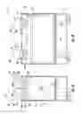
FIGS. 1A and B schematically illustrate, respectively, a front view and a side view of an air handler with multiple fans with panels removed to show interior components therein;
FIG. 2 schematically illustrates an HVAC system using an air handler with multiple fans.
DETAILED DESCRIPTION OF THE ENCLOSED EMBODIMENTS
For the purposes of promoting an understanding of the principles of the present disclosure, reference will now be made to the embodiments illustrated in the drawings, and specific language will be used to describe the same. It will nevertheless be understood that no limitation of the scope of this disclosure is thereby intended.
FIGS. 1A and B illustrate an embodiment of an air handler with multiple fans, generally indicated at 10. The front and side walls of the air handler 10 have been removed to illustrate the interior components of the air handler 10. Air handler 10 includes a first enclosure 12 to contain the components therein, and a plurality of air distribution modules 14 affixed to the first enclosure 12. Air handler 10 also includes a controller 16 to operate at least one of the plurality of air distribution modules 14. Air handler 10 further includes a coil 18 disposed within the first enclosure 12 to allow a liquid to flow therethrough.
The first enclosure 12 contains a first interior volume 20. In one embodiment, a ventilation device 36 is operatively coupled to air handler 10 to draw fresh air into the first interior volume 20 through a first air inlet opening (not shown). A second air inlet opening (not shown) may be provided in the air handler first enclosure 12. The second air inlet opening can be covered by an air filter, to name one non-limiting example that allows ambient air in the environment surrounding the first enclosure 12 to easily pass through the opening and enter the first interior volume 20. Air handler 10 includes the coil 18 disposed within the first enclosure 12. The coil 18 allows a liquid to flow therethrough when responding to a demand for conditioning an interior zone. The coil 18 may be composed of copper or aluminum, and arranged in a tube and fin configuration, to name just a few non-limiting examples.
Each of the plurality of air distribution modules 14 includes a second enclosure 22 enclosing a second interior volume 24. The second enclosure 22 is adapted for communication of an air distribution stream from the first interior volume 20 to the second interior volume 24. The second enclosure 22 is further adapted for communication of an air distribution stream from the second interior volume 24 to an external environment of the first enclosure 12 and second enclosure 22.
The front and side walls of each of the plurality of air distribution modules 14 has been removed to illustrate the interior components therein. In an exemplary embodiment, each of the plurality of air distribution modules 14 includes a damper 26 disposed within the second enclosure 22. Damper 26 may be of any desired shape, such as a rectangular, square, or oval shape blade, composed of any desired material, such as aluminized steel or stainless steel, to name just a few non-limiting examples. Damper 26 operates between an open and a closed position, and a number of positions therebetween, to regulate an amount of air allowed to flow through the second interior volume 24. In an exemplary embodiment, each of the plurality of air distribution modules 14 includes a fan 28 disposed within the second enclosure 22. Fan 28 may be a brushless direct-current powered axial fan, to name just one non-limiting example. Fan 28 operates to circulate air through the second interior volume 24.
In one embodiment, each of the plurality of air distribution modules 14 includes an electrical heating element 30 disposed within the second enclosure 22 for providing auxiliary heating. In one embodiment, the electrical heating element 30 is a nickel chromium conductive wire, to name just one non-limiting example.
A controller 16 is provided in communication, such as electrical communication, with each of the plurality of air distribution modules 14. Controller 16 may be disposed within first enclosure 12. In one embodiment, the controller 16 includes a microprocessor, pre-programmed with software stored in non-volatile memory for executing instructions to operate the air handler 10.
FIG. 2 illustrates an embodiment of a HVAC system, generally indicated at 32 The HVAC system 32 includes an air handler with multiple fans 10 operatively coupled to an outdoor unit assembly 34 via conduits 38. The air handler 10 and the outdoor unit assembly 34 are configured to circulate a refrigerant therethrough. In one embodiment, outdoor unit assembly unit 34 may be a heat pump, while in another embodiment, outdoor unit assembly 34 may be an air conditioner, to name just two non-limiting examples. In one embodiment, the HVAC system 32 includes conduits 40 and 42 coupled to air distribution modules 14A and 14B respectively, of air handler 10 to distribute air into different interior zones. It will be appreciated by those skilled in the art that there may be more than two air distribution modules and more than two conduits depending on the configuration of the interior zones. In another embodiment, the HVAC system 32 includes a ventilation device 36 operatively coupled to the air handler 10.
In an exemplary embodiment of HVAC system 32, controller 16 receives a signal from a sensor designating a demand to condition an interior zone. The demand to condition an interior zone may come from Zone A, Zone B, or both. It will be appreciated by those skilled in the art that there may be more than two zones designating a demand call to condition an interior zone. For the purpose of illustration, it is designated that Zone A initiated a demand call. If a demand was initiated from Zone B, the system 32 would operate in similar fashion. Controller 16 sends a signal to the outdoor unit assembly 34 to begin circulating the refrigerant through a conduit circuit 38 to the coil 18. Once the refrigerant has circulated through the coil 18 for a specified period of time, controller 16 sends an electrical signal to damper 26A to be placed in an open position. Controller 16 sends an electrical signal to begin rotating fan 28A to circulate air. Fan 28A circulates the conditioned air from the first interior volume 20 through the second interior volume 24 to the desired zone, via conduit 40, to satisfy the demand. After the demand is satisfied, controller 16 sends an electrical signal to remove power from fan 28A. Controller 16 also sends an electrical signal to place damper 26A into a closed position. Controller 16 additionally sends an electrical signal to the outdoor unit assembly 34 to stop circulating the refrigerant.
If auxiliary heating is required, power is supplied to the electrical heating element 30A. Controller 16 sends a signal to damper 26A to be placed in an open position. Controller 16 also sends a signal to begin rotating fan 28A to circulate air. Fan 28A circulates the conditioned air through the second interior volume 24 to the desired zone, via conduit 40, to satisfy the demand. After the demand is satisfied, controller 16 sends an electrical signal to remove power from the electrical heating element 30A. Controller 16 also sends an electrical signal to remove power from fan 28A. Controller 16 additionally sends an electrical signal to place damper 26A in a closed position.
In another embodiment of HVAC system 32, if more than one zone is designating a demand to condition the interior zone, controller 16 will operate each of the plurality of air distribution modules 14A and 14B in the manner described herein.
In another embodiment of HVAC system 32, system 32 circulates fresh air through an interior zone by adding ventilator device 36. Controller 16 sends a signal to ventilation device 36 to begin operating fans therein to pull fresh air into the device while simultaneously exhausting stale air from the interior space. Controller 16 also sends a signal to damper 26A to be placed in an open position. Controller 16 additionally sends a signal to begin rotating fan 28A. Fan 28A circulates the fresh air, pulled from the ventilation device 36, from the first interior volume 20 through the second interior volume 24 to the desired zone to satisfy the demand. After the demand is satisfied, controller 16 sends an electrical signal to ventilation device 36 to stop operating. Controller 16 also sends an electrical signal to remove power from fan 28A. Controller 16 additionally sends a signal to place damper 26A in a closed position. If more than one zone is designating a demand to provide fresh air to the interior zone, controller 16 will operate each of the plurality of air distribution modules 14A and 14B in the manner described herein.
It will be appreciated that, air handler 10 can satisfy a demand for conditioned or fresh air within two or more interior zones by operating an air distribution module 14 associated with each interior zone. Air handler 10 operates a fan 28 and a damper 26, within each air distribution module 14, to direct and circulate conditioned or fresh air to each interior zone.
While the invention has been illustrated and described in detail in the drawings and foregoing description, the same is to be considered as illustrative and not restrictive in character, it being understood that only certain embodiments have been shown and described and that all changes and modifications that come within the spirit of the invention are desired to be protected.
Claims
What is claimed is:1. A HVAC system for conditioning an interior zone comprising:
an air handler configured to operate at least one of a plurality air distribution modules affixed to the air handler.
2. The system of claim 1, further comprising an outdoor unit assembly operatively coupled to the air handler for exchange of a refrigerant therebetween.
3. The system of claim 1, further comprising a conduit affixed to each of the plurality of air distribution modules to distribute air to an interior zone.
4. The system of claim 2, wherein the outdoor unit assembly is selected from the group consisting of: a heat pump and an air conditioner.
5. The system of claim 1, further comprising a ventilation device operatively coupled to the air handler for circulating fresh air to an interior zone.
6. An air distribution module comprising:
an enclosure having an interior volume, a distribution air inlet opening, and a distribution air outlet opening that are adapted for communication of a distribution air stream;
a damper, disposed within the enclosure, configured to operate between an open and closed position, and a number of positions therebetween; and
a fan, disposed within the enclosure, configured to circulate air through the enclosure
wherein the enclosure is configured to be affixed on an air handler.
7. The air distribution module of claim 6 further comprising:
an electrical heating element, disposed within the enclosure, configured to provide auxiliary heat.
8. An air handler comprising:
a plurality of fans configured to provide and direct conditioned air or fresh air to respective multiple zones of a building.
9. The air handler of claim 8, further comprising
a first enclosure, wherein a coil and a controller are disposed within the first enclosure;
a plurality of second enclosures, wherein at least one of the plurality of fans is disposed inside each of the plurality of second enclosures; wherein each of the second enclosures are affixed to the first enclosure, and wherein the plurality of second enclosures are adapted for communication of a distribution air stream.
a damper disposed within each the plurality of second enclosures; wherein the controller is in operable communication with the plurality of fans and the damper.
Images & Drawings included:


Sources:
- United States Patent and Trademark Office - verify current appl. status at the USPTO↗
Similar patent applications:
- » 20140260408
Compact air handler with multiple fans
Recent applications in this class:
- » 20250020347 2025-01-16
AIR CONDITIONING APPLIANCES AND HEAT RECOVERY FEATURES THEREOF - » 20250003611 2025-01-02
BATHROOM EXHAUST FAN SWITCHING DEVICE - » 20240426492 2024-12-26
VENTILATION UNIT - » 20240280278 2024-08-22
EMBEDDED VENTILATION FAN - » 20240210056 2024-06-27
VENTILATION SYSTEM - » 20240159407 2024-05-16
Ventilating system - » 20240102674 2024-03-28
Bypass Ventilator - » 20240035681 2024-02-01
AIR TREATMENT DEVICE - » 20240003559 2024-01-04
Air moving device with bypass intake - » 20230400200 2023-12-14
VENTILATION DEVICE