Inlet for axial fan
US20190178252A1
2019-06-13
16/099,121
2017-05-03
✅ Patent granted
US 11,226,114 B2
2022-01-18
WO; PCT/US2017/030728; 20170503
WO; WO2017/192647; 20171109
Richard A Edgar | Aye S Htay
Cantor Colburn LLP
2037-05-03
Abstract:
A fan assembly (10) includes a shrouded fan rotor (18) having a plurality of fan blades (22) extending from a rotor hub (24) and rotatable about a central axis (20) of the fan assembly, and a fan shroud (26) extending circumferentially around the fan rotor (18) and secured to an outer tip diameter of the plurality of fan blades (22). A fan casing (16) encloses the shrouded fan rotor (18). The fan casing (16) defines a fan inlet (30) of the fan assembly and includes an inlet extension (54) at an outer diameter of the fan casing, extending axially upstream of a conventional bell mouth inlet (58), relative to a direction of airflow through the shrouded fan rotor (18).
Assignee:
- Carrier Corporation 1,328 🇺🇸 Palm Beach Gardens, FL, United States
Applicant:
Interested in similar patents?
Get notified when new applications in this technology area are published.
Classification:
F24F2013/205 » CPC further
Details common to, or for air-conditioning, air-humidification, ventilation or use of air currents for screening; Casings or covers Mounting a ventilator fan therein
F04D25/12 » CPC further
Pumping installations or systems; Units comprising pumps and their driving means the working fluid being air, e.g. for ventilation the unit being adapted for mounting in apertures
F24F13/20 » CPC further
Details common to, or for air-conditioning, air-humidification, ventilation or use of air currents for screening Casings or covers
F04D29/34 » CPC further
Details, component parts, or accessories; Rotors specially for elastic fluids for axial flow pumps Blade mountings
F04D29/38 » CPC further
Details, component parts, or accessories; Rotors specially for elastic fluids for axial flow pumps Blades
F04D19/002 » CPC main
Axial-flow pumps Axial flow fans
F04D29/66 IPC
Details, component parts, or accessories Combating cavitation, whirls, noise, vibration or the like ; Balancing
F24F1/0323 » CPC further
Room units for air-conditioning, e.g. separate or self-contained units or units receiving primary air from a central station; Self-contained room units for air-conditioning, i.e. with all apparatus for treatment installed in a common casing characterised by heat exchangers by the mounting or arrangement of the heat exchangers
F24F1/0287 » CPC further
Room units for air-conditioning, e.g. separate or self-contained units or units receiving primary air from a central station; Self-contained room units for air-conditioning, i.e. with all apparatus for treatment installed in a common casing characterised by air supply means, e.g. fan casings, internal dampers or ducts with vertically arranged fan axis
F04D25/06 » CPC further
Pumping installations or systems; Units comprising pumps and their driving means the pump being electrically driven
F04D29/544 » CPC further
Details, component parts, or accessories; Casings; Connections of working fluid for axial pumps; Fluid-guiding means, e.g. diffusers; Specially adapted for elastic fluid pumps; Bladed diffusers Blade shapes
F04D29/54 IPC
Details, component parts, or accessories; Casings; Connections of working fluid for axial pumps Fluid-guiding means, e.g. diffusers
F04D29/541 » CPC further
Details, component parts, or accessories; Casings; Connections of working fluid for axial pumps; Fluid-guiding means, e.g. diffusers Specially adapted for elastic fluid pumps
F04D29/542 » CPC further
Details, component parts, or accessories; Casings; Connections of working fluid for axial pumps; Fluid-guiding means, e.g. diffusers; Specially adapted for elastic fluid pumps Bladed diffusers
F04D29/667 » CPC further
Details, component parts, or accessories; Combating cavitation, whirls, noise, vibration or the like ; Balancing especially adapted for elastic fluid pumps by influencing the flow pattern, e.g. suppression of turbulence
F24F1/029 » CPC main
Room units for air-conditioning, e.g. separate or self-contained units or units receiving primary air from a central station; Self-contained room units for air-conditioning, i.e. with all apparatus for treatment installed in a common casing characterised by the layout or mutual arrangement of components, e.g. of compressors or fans
F04D19/00 IPC
Axial-flow pumps
F24F1/0029 » CPC further
Room units for air-conditioning, e.g. separate or self-contained units or units receiving primary air from a central station; Indoor units, e.g. fan coil units characterised by fans Axial fans
Description
BACKGROUND
The subject matter disclosed herein relates to vane axial flow fans. More specifically, the subject matter disclosed herein relates to structures to improve fan stall performance and/or improve stall recovery hysteresis performance of vane axial flow fans.
Axial flow fans are widely used in many industries ranging from automotive to aerospace to HVAC but are typically limited in their application by operating range restrictions and noise considerations. While vane-axial fans can achieve high static efficiencies, their limited operating range due to blade stall typically makes the vane-axial fan impractical for use in many systems that have extended operating range requirements. Furthermore, the stall and stall recovery performance of an axial fan can be degraded due to sensitivity to non-optimal or off-design inflow conditions. For example, when an axial fan is subjected to inflow that is substantially at a right angle to the axis of rotation of the fan, the fan may experience reduced stall performance and/or increased stall recovery hysteresis. In certain HVAC applications, such as an indoor fan system for a residential or commercial packaged product or split system, the reduction in operating range driven by this deficient stall/recovery hysteresis performance can hinder the application of vane-axial fan technology.
SUMMARY
In one embodiment, a fan assembly includes a shrouded fan rotor having a plurality of fan blades extending from a rotor hub and rotatable about a central axis of the fan assembly, and a fan shroud extending circumferentially around the fan rotor and secured to an outer tip diameter of the plurality of fan blades. A fan casing encloses the shrouded fan rotor. The fan casing defines a fan inlet of the fan assembly and includes an inlet extension at an outer diameter of the fan casing, extending axially upstream of a conventional bell mouth inlet, relative to a direction of airflow through the shrouded fan rotor.
Additionally or alternatively, in this or other embodiments the inlet extension extends between 5% and 20% of the fan rotor tip diameter axially upstream of the conventional bell mouth inlet.
Additionally or alternatively, in this or other embodiments the conventional bell mouth inlet transitions to the inlet extension, the inlet extension including a convex portion and a concave portion.
Additionally or alternatively, in this or other embodiments the concave portion extends from an inlet extension leading edge axially to a transition point and the convex portion extends from the transition point to a rotor leading edge.
Additionally or alternatively, in this or other embodiments the convex portion axially overlaps the fan shroud.
Additionally or alternatively, in this or other embodiments the inlet extension tapers radially from the conventional bell mouth inlet to an inlet extension leading edge at a taper angle.
Additionally or alternatively, in this or other embodiments the taper angle is between 0.5 degrees and 45 degrees.
Additionally or alternatively, in this or other embodiments a primary direction of airflow approaching the fan inlet is transverse relative to the central axis.
In another embodiment, a casing assembly for an axial fan includes a fan casing extending circumferentially about a central axis, the fan casing defining a fan inlet of the axial fan, and an inlet extension at an outer diameter of the casing, extending axially upstream of a conventional bell mouth inlet, relative to a direction of airflow through the shrouded fan rotor.
Additionally or alternatively, in this or other embodiments the inlet extension includes a concave surface extending from an inlet extension leading edge axially to a transition point and a convex portion extending axially rearwardly from the transition point.
Additionally or alternatively, in this or other embodiments the inlet extension is configured to extend axially upstream of a conventional bell mouth inlet, relative to a direction of airflow through the fan assembly.
Additionally or alternatively, in this or other embodiments the inlet extension is configured to extend between 5% and 20% of the fan rotor tip diameter axially upstream of the conventional bell mouth inlet.
Additionally or alternatively, in this or other embodiments the inlet extension tapers radially from the conventional bell mouth inlet to an inlet extension leading edge at a taper angle.
Additionally or alternatively, in this or other embodiments the taper angle is between 0.5 degrees and 45 degrees.
Additionally or alternatively, in this or other embodiments the inlet extension is configured to axially overlap a fan shroud of the fan assembly.
Additionally or alternatively, in this or other embodiments a primary direction of airflow approaching the fan inlet is transverse relative to the central axis.
BRIEF DESCRIPTION OF THE DRAWINGS
The subject matter is particularly pointed out and distinctly claimed at the conclusion of the specification. The foregoing and other features, and advantages of the present disclosure are apparent from the following detailed description taken in conjunction with the accompanying drawings in which:
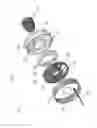
FIG. 1 is a perspective view of an embodiment of a fan assembly;
FIG. 2 is another cross-sectional view of an embodiment of a fan assembly; and
FIG. 3 is another partial cross-sectional view of an embodiment of a fan assembly.
The detailed description explains embodiments of the invention, together with advantages and features, by way of example with reference to the drawing.
DETAILED DESCRIPTION
Shown in FIG. 1 is a partially exploded perspective view of an embodiment of an axial-flow fan 10 utilized, for example in a heating, ventilation and air conditioning (HVAC) system as an air handling fan. The fan 10 may be driven by an electric motor 12 connected to the fan 10 by a shaft (not shown), or alternatively a belt or other arrangement. In operation, the motor 12 drives rotation of the fan 10 to urge airflow 14 across the fan 10 and along a flowpath, for example, to or from a heat exchanger (not shown). The fan 10 includes a casing 16 with a fan rotor 18, or impeller rotably located in the casing 16. Operation of the motor 12 drives rotation of the fan rotor 18 about a fan axis 20. The fan rotor 18 includes a plurality of fan blades 22 extending from a hub 24 and terminating at a fan shroud 26. The fan shroud 26 is connected to one or more fan blades 22 of the plurality of fan blades 22 and rotates about the fan axis 20 therewith. The fan 10 further includes a stator assembly 28 including a plurality of stator vanes 30, located downstream of the fan rotor 18. The plurality of stator vanes 30 extend substantially radially from a stator hub 32 to a stator shroud 34.
Referring now to FIG. 2, in some applications, such as a rooftop or other packaged product heating, ventilation, air conditioning and refrigeration (HVAC&R) system, the fan 10 is oriented such that the airflow 14 directed at a fan inlet 50 of the fan 10 is from a direction predominantly perpendicular to the fan axis 20. Thus, to flow along the fan axis 20, the airflow 14 must be turned 90 degrees before flowing through the fan 10 and, for example, across a downstream heat exchange surface 52 of the HVAC&R system. This side-flow condition at the fan inlet 50 can result in poor stall and stall recovery hysteresis performance of the fan 10, and may limit an operating range of the fan 10, and thus its use in such applications.
Referring now to FIG. 3, the fan inlet 50 includes a casing extension 54 extending axially forward of a conventional bell mouth inlet 58, in some embodiments the casing extension 54 extends in the range of about 5% to about 20% of the fan rotor tip diameter axially forward of a conventional bell mouth inlet 58. The casing extension 54 provides axial distance for turning of the airflow 14 toward the axial direction along the fan axis 20 prior to entering the fan rotor 18. With a casing extension 54 length of about one inch, a reduction in stall recovery hysteresis of about 70% has been achieved, when compared with a comparable fan without the casing extension 54 that is applied in an installation with predominantly perpendicular inflow as shown in FIG. 2.
The casing extension 54 extends axially upstream of a conventional bell mouth inlet 58 to condition the airflow 14 prior to the airflow entering the fan rotor 18. A casing extension leading edge 60 defines an axially forward-most portion of the casing extension 54. In some embodiments, the casing extension 54 is formed integral with the conventional bell mouth inlet 58, while in other embodiments the casing extension 54 is a separate component from and discontinuous with the conventional bell mouth inlet 58.
In some embodiments, the casing extension 54 is an axial ring extending upstream of the conventional bell mouth inlet 58. In other embodiments, the casing extension 58 transitions from the conventional bell mouth inlet 58 at an inlet angle 80 (shown in FIG. 2). In some embodiments, the inlet angle 80 is in the range of 0.5 degrees to 45 degrees, with in other embodiments, the inlet angle 80 is between 10 and 40 degrees, while in still other embodiments the inlet angle 80 is between 15 and 30 degrees.
In some embodiments, as shown in FIG. 3, the casing extension leading edge 60 transitions to the conventional bell mouth inlet 58 via a concave portion 62 extending from the casing extension leading edge 60 axially to a transition point 64, and a convex portion 66 extending from the transition point 64 to a rotor leading edge 68. In some embodiments, the convex portion 68 axially overlaps the fan shroud 26.
While ideally an axially longer casing extension 54 improves the condition of airflow 14 entering the fan rotor 18, the performance improvement of the fan 10 must be balanced with packaging constraints on the fan 10.
The utilization of casing extension 54 in the fan 10 improves stall performance of the fan 10 and further reduces stall recovery hysteresis in comparison to prior fans. These improvements allow for expansion of the operating envelope of shrouded axial fans, thus increasing their applicability to a wide range of conditions, such as rooftop HVAC&R systems, allowing such systems to take advantage of the performance advantages of shrouded axial fans.
While the present disclosure has been described in detail in connection with only a limited number of embodiments, it should be readily understood that the present disclosure is not limited to such disclosed embodiments. Rather, the present disclosure can be modified to incorporate any number of variations, alterations, substitutions or equivalent arrangements not heretofore described, but which are commensurate in spirit and/or scope. Additionally, while various embodiments have been described, it is to be understood that aspects of the present disclosure may include only some of the described embodiments. Accordingly, the present disclosure is not to be seen as limited by the foregoing description, but is only limited by the scope of the appended claims.
Claims
1. A fan assembly, comprising
a shrouded fan rotor including:
a plurality of fan blades extending from a rotor hub and rotatable about a central axis of the fan assembly; and
a fan shroud extending circumferentially around the fan rotor and secured to an outer tip diameter of the plurality of fan blades; and
a fan casing enclosing the shrouded fan rotor, the fan casing defining a fan inlet of the fan assembly and including an inlet extension at an outer diameter of the fan casing, extending axially upstream of a conventional bell mouth inlet, relative to a direction of airflow through the shrouded fan rotor.
2. The fan assembly of claim 1, wherein the inlet extension extends between 5% and 20% of the fan rotor tip diameter axially upstream of the conventional bell mouth inlet.
3. The fan assembly of claim 1, wherein the conventional bell mouth inlet transitions to the inlet extension, the inlet extension including a convex portion and a concave portion.
4. The fan assembly of claim 3, wherein the concave portion extends from an inlet extension leading edge axially to a transition point and the convex portion extends from the transition point to a rotor leading edge.
5. The fan assembly of claim 3, wherein the convex portion axially overlaps the fan shroud.
6. The fan assembly of claim 1, wherein the inlet extension tapers radially from the conventional bell mouth inlet to an inlet extension leading edge at a taper angle.
7. The fan assembly of claim 6, wherein the taper angle is between 0.5 degrees and 45 degrees.
8. The fan assembly of claim 1, wherein a primary direction of airflow approaching the fan inlet is transverse relative to the central axis.
9. A casing assembly for an axial fan, comprising
a fan casing extending circumferentially about a central axis, the fan casing defining a fan inlet of the axial fan; and
an inlet extension at an outer diameter of the casing, extending axially upstream of a conventional bell mouth inlet, relative to a direction of airflow through the shrouded fan rotor.
10. The casing assembly of claim 9, the inlet extension includes a concave surface extending from an inlet extension leading edge axially to a transition point and a convex portion extending axially rearwardly from the transition point.
11. The casing assembly of claim 9, wherein the inlet extension is configured to extend axially upstream of a conventional bell mouth inlet, relative to a direction of airflow through the fan assembly.
12. The casing assembly of claim 11, wherein the inlet extension is configured to extend between 5% and 20% of the fan rotor tip diameter axially upstream of the conventional bell mouth inlet.
13. The casing assembly of claim 9, wherein the inlet extension tapers radially from the conventional bell mouth inlet to an inlet extension leading edge at a taper angle.
14. The casing assembly of claim 13, wherein the taper angle is between 0.5 degrees and 45 degrees.
15. The casing assembly of claim 9, wherein the inlet extension is configured to axially overlap a fan shroud of the fan assembly.
16. The casing assembly of claim 9, wherein a primary direction of airflow approaching the fan inlet is transverse relative to the central axis.
Images & Drawings included:


Sources:
- United States Patent and Trademark Office - verify current appl. status at the USPTO↗
Similar patent applications:
- » 20160040937
Axial fan inlet wind-turning vane assembly - » 20180142702
Inlet nozzle for a radial, diagonal or axial-flow fan, and a radial, diagonal or axial-flow fan comprising an inlet nozzle - » 20120036998
Electrostatic control of air flow to the inlet opening of an axial fan - » 20130177391
Electrostatic control of air flow to the inlet opening of an axial fan - » 20050281692
Axial-flow type fan having an air inlet blade structure tipped with leading corners - » 20230022241
Lighting ventilation fan having axial function module and grille with lateral inlet
Recent applications in this class:
- » 20250277491 2025-09-04
AXIAL FAN - » 20250270998 2025-08-28
FAN ASSEMBLY AND SERVER - » 20250198417 2025-06-19
VEHICLE FAN INSTALLATION ASSEMBLY - » 20250188940 2025-06-12
COOLING FAN WITH SPEED AND TEMPERATURE DISPLAY - » 20250180031 2025-06-05
AXIAL FAN FOR AN AIR HANDLING UNIT - » 20250146494 2025-05-08
AXIAL FLOW BLOWER - » 20250146493 2025-05-08
A Fan With Lighting Effect - » 20250075704 2025-03-06
FAN DEVICE - » 20250052249 2025-02-13
PORTABLE BLOWER FAN ASSEMBLY - » 20250027502 2025-01-23
AXIAL-FLOW HEAT-DISSIPATION FAN
Recent applications for this Assignee:
- » 20240401843 2024-12-05
ROOFTOP HVAC UNIT - » 20240351398 2024-10-24
POWER DISTRIBUTION IN TRANSPORT REFRIGERATION SYSTEM - » 20240300060 2024-09-12
TOOL KIT FOR HEAT EXCHANGER AND METHOD OF DETACHING HEAT EXCHANGER END COVER - » 20240263854 2024-08-08
RECEIVER, CONNECTION METHOD THEREOF, RECEIVER ASSEMBLY AND HEAT PUMP SYSTEM - » 20240233465 2024-07-11
METHOD AND SYSTEM FOR SWITCHING THE PREMISES - » 20240175600 2024-05-30
Redundant power supply for HVAC system including refrigerant leakage mitigation - » 20240146100 2024-05-02
BATTERY PACK, AIR CONDITIONING SYSTEM, AND METHOD FOR THE SAME - » 20240135763 2024-04-25
Method and system for switching the premises - » 20240102472 2024-03-28
DIRECT DRIVE REFRIGERANT SCREW COMPRESSOR WITH REFRIGERANT LUBRICATED ROTORS - » 20240079690 2024-03-07
Enclosure for an electronic device and associated manufacturing method