Internal combustion engine
US20190186320A1
2019-06-20
16/326,414
2017-08-07
✅ Patent granted
US 10,934,915 B2
2021-03-02
WO; PCT/EP2017/000958; 20170807
WO; WO2018/036647; 20180301
Jonathan R Matthias
Davidson, Davidson & Kappel, LLC
2037-08-07
Abstract:
An internal combustion engine including a urea-water solution injection in the exhaust system, includes at least one urea-water solution tank, at least one pump, at least one intake line leading to the pump, at least one urea-water solution metering valve which is connected to the pump with the aid of a pressure line, and at least one return line which leads from the pump to the urea-water solution tank and at whose end opposite to the pump a filter element is situated, as well as at least one urea-water solution sensor situated in the urea-water solution tank.
Inventors:
- Ralph STENGEL 1 🇩🇪 Koeln, Germany
- Dominic WEBER 1 🇩🇪 Pulheim, Germany
- Peter BROLL 5 🇩🇪 Bergisch-Gladbach, Germany
- Daniel DAMMER 1 🇩🇪 Koeln, Germany
- Ralph Stengel 1 🇩🇪 Cologne, Germany
- Daniel Dammer 1 🇩🇪 Cologne, Germany
Assignee:
- Deutz Aktiengesellschaft 46 🇩🇪 Cologne, Germany
Applicant:
Interested in similar patents?
Get notified when new applications in this technology area are published.
Classification:
B01D29/904 » CPC further
Other filters with filtering elements stationary during filtration, e.g. pressure or suction filters, or filtering elements therefor having feed or discharge devices for feeding directing the mixture to be filtered on the filtering element in a manner to clean the filter continuously
F01N3/2066 » CPC main
Exhaust or silencing apparatus having means for purifying, rendering innocuous, or otherwise treating exhaust for rendering innocuous by thermal or catalytic conversion of noxious components of exhaust characterised by methods of operation; Control specially adapted for catalytic conversion ; Methods of operation or control of catalytic converters Selective catalytic reduction [SCR]
B01D39/16 IPC
Filtering material for liquid or gaseous fluids; Other self-supporting filtering material ; Other filtering material of organic material, e.g. synthetic fibres
B01D39/20 IPC
Filtering material for liquid or gaseous fluids; Other self-supporting filtering material ; Other filtering material of inorganic material, e.g. asbestos paper, metallic filtering material of non-woven wires
B01D39/2017 » CPC further
Filtering material for liquid or gaseous fluids; Other self-supporting filtering material ; Other filtering material of inorganic material, e.g. asbestos paper, metallic filtering material of non-woven wires; Glass or glassy material the material being filamentary or fibrous
B01D39/2034 » CPC further
Filtering material for liquid or gaseous fluids; Other self-supporting filtering material ; Other filtering material of inorganic material, e.g. asbestos paper, metallic filtering material of non-woven wires; Metallic material the material being particulate sintered or bonded by inorganic agents
B01D53/9431 » CPC further
Separation of gases or vapours; Recovering vapours of volatile solvents from gases; Chemical or biological purification of waste gases, e.g. engine exhaust gases, smoke, fumes, flue gases, aerosols,; Chemical or biological purification of waste gases of engine exhaust gases by catalytic processes; Removing only nitrogen compounds; Nitrogen oxides Processes characterised by a specific device
B01D2239/0208 » CPC further
Aspects relating to filtering material for liquid or gaseous fluids; Types of fibres, filaments or particles, self-supporting or supported materials Single-component fibres
B01D2239/0618 » CPC further
Aspects relating to filtering material for liquid or gaseous fluids; Filter cloth, e.g. knitted, woven non-woven; self-supported material; Arrangement of the fibres in the filtering material Non-woven
B01D2239/1216 » CPC further
Aspects relating to filtering material for liquid or gaseous fluids; Special parameters characterising the filtering material Pore size
F01N2610/02 » CPC further
Adding substances to exhaust gases the substance being ammonia or urea
F01N2610/10 » CPC further
Adding substances to exhaust gases the substance being heated, e.g. by heating tank or supply line of the added substance
F01N2610/1406 » CPC further
Adding substances to exhaust gases; Arrangements for the supply of substances, e.g. conduits Storage means for substances, e.g. tanks or reservoirs
F01N2610/1433 » CPC further
Adding substances to exhaust gases; Arrangements for the supply of substances, e.g. conduits Pumps
F01N2610/1453 » CPC further
Adding substances to exhaust gases; Arrangements for the supply of substances, e.g. conduits Sprayers or atomisers; Arrangement thereof in the exhaust apparatus
F01N2610/1466 » CPC further
Adding substances to exhaust gases; Arrangements for the supply of substances, e.g. conduits Means for venting air out of conduits or tanks
F01N3/20 IPC
Exhaust or silencing apparatus having means for purifying, rendering innocuous, or otherwise treating exhaust for rendering innocuous by thermal or catalytic conversion of noxious components of exhaust characterised by methods of operation; Control specially adapted for catalytic conversion ; Methods of operation or control of catalytic converters
B01D29/90 IPC
Other filters with filtering elements stationary during filtration, e.g. pressure or suction filters, or filtering elements therefor having feed or discharge devices for feeding
B01D39/14 » CPC further
Filtering material for liquid or gaseous fluids Other self-supporting filtering material ; Other filtering material
B01D39/1615 » CPC further
Filtering material for liquid or gaseous fluids; Other self-supporting filtering material ; Other filtering material of organic material, e.g. synthetic fibres the material being fibrous of natural origin
B01D53/94 IPC
Separation of gases or vapours; Recovering vapours of volatile solvents from gases; Chemical or biological purification of waste gases, e.g. engine exhaust gases, smoke, fumes, flue gases, aerosols,; Chemical or biological purification of waste gases of engine exhaust gases by catalytic processes
F01N2610/1426 » CPC further
Adding substances to exhaust gases; Arrangements for the supply of substances, e.g. conduits Filtration means
B01D19/0031 » CPC further
Degasification of liquids by filtration
F01N2610/14 » CPC further
Adding substances to exhaust gases Arrangements for the supply of substances, e.g. conduits
F01N2610/148 » CPC further
Adding substances to exhaust gases; Arrangements for the supply of substances, e.g. conduits Arrangement of sensors
F01N2610/1473 » CPC further
Adding substances to exhaust gases; Arrangements for the supply of substances, e.g. conduits Overflow or return means for the substances, e.g. conduits or valves for the return path
F01N13/08 IPC
Exhaust or silencing apparatus characterised by constructional features ; Exhaust or silencing apparatus, or parts thereof, having pertinent characteristics not provided for in, or of interest apart from, groups - , , Other arrangements or adaptations of exhaust conduits
B01D19/00 IPC
Degasification of liquids
Description
The present invention relates to an internal combustion engine including a urea-water solution injection in the exhaust system as well as a method for degasification and filtration.
Degasification refers to removing gases and other volatile substances from liquids and solids in a controlled manner.
BACKGROUND
The elimination of dissolved substances or of substances confined in the form of bubbles, prevents further possible negative effects, such as hydrogen embrittlement of steel, deterioration of materials due to oxidation, hydrolysis due to moisture, corrosion of steam boilers, pipes, etc. due to oxygen and carbon dioxide in the liquid, and failure of hydraulic systems by increased compressibility. The most commonly used method for degasification is to subject the material to be degassed to a vacuum. If ultrasound is introduced into a liquid, for example via a sonotrode, a high-frequency alternating pressure field is formed therein. The short-term negative pressure which is periodically formed results in cavities. This effect is referred to as cavitation. The cavities are formed at gas pockets, for example, which act as cavitation nuclei. The dissolved gas diffuses into the cavitation bubbles and prevents them from completely imploding during the subsequent pressure increase: The bubbles grow with every oscillation process. If standing waves are formed through reflections, the bubbles are pushed to their nodes, where they coalesce and ultimately migrate to the surface as a result of their buoyancy. Due to the temperature dependency of the Henry constant, a degasification may also be achieved solely by raising the temperature. The easiest possibility is to feed energy at decreased pressure and is referred to as boiling in vacuum. This effect may be observed during the normal boiling procedure; air bubbles forming in the water in this case.
Devices of this type are described, for example, in WO 2013029950 A1, where so-called gas traps are used to catch air bubbles or in DE 102007012918 A1, where tiny air bubbles, which are retained in a filter, are generated by high-frequency opening and closing of a liquid valve. The disadvantage here is that, as is the case in WO 2013029950 A1, tiny gas bubbles linger rather randomly at different locations. Or, as is the case in DE 102007012918 A1, tiny bubbles are generated instead of removed.
SUMMARY OF THE INVENTION
It is an object of the present invention to prevent the disadvantages mentioned above and to provide a device and a method which reliably degas and filter a urea-water solution.
The present invention provides an internal combustion engine including a urea-water solution injection in the exhaust system, including at least one urea-water solution tank, at least one pump, at least one intake line leading to the pump, at least one urea-water solution metering valve which is connected to the pump with the aid of a pressure line, and at least one return line which leads from the pump to the urea-water solution tank and at whose end opposite to the pump a filter element is situated, as well as at least one urea-water solution sensor situated in the urea-water solution tank, and a method for degasification and filtration of the urea-water solution, in particular for use in an internal combustion engine.
The urea-water solution sensor measures the proportion of urea in the solution with water. This takes place, for example, by measuring the density with the aid of ultrasound or infrared measurement. Tiny bubbles in the measuring path of the sensor falsify the measuring result. The advantage of the present invention is the prevention or reduction of the entry of tiny bubbles (which have formed in the pump or in the lines, for example) into the urea-water solution tank, whereby suitable measuring conditions for the urea-water solution sensor are achieved.
It is provided in one advantageous refinement that the filter is a precoat filter or a cartridge filter, or a spatial filter, or a multi-layer bed filter, or a magnetic filter.
Another advantageous refinement provides that the filter includes flexible filter media or rigid filter media or packed beds.
One advantageous refinement provides that the filter material is a strainer or a paper filter or a glass fiber mat, or a ceramic, or a sintered metal, or a needle felt.
It is provided in another advantageous refinement that the pore size of the filter is smaller than 70 micrometers.
It is provided in another advantageous refinement that the filter is a two-dimensional filter or a three-dimensional filter or a multilayer filter or a surface filter or a depth filter.
One advantageous refinement provides that the urea-water solution tank is subjected to a vacuum and/or is provided with venting additives.
It is provided in another advantageous refinement that the urea-water solution tank includes an ultrasound generator and/or a heater, the ultrasound generator being situated in the quality sensor.
BRIEF DESCRIPTION OF THE DRAWINGS
Exemplary specific embodiments of the present invention are described in the figures and explained in greater detail in the following description.
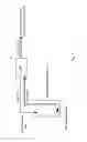
FIG. 1 shows a schematic representation of the urea-water solution tank up to the injector
FIG. 2 shows a schematic representation of the internal combustion engine including the urea-water solution tank and metering valve]
FIG. 3 shows a variant of the representation in FIG. 2 including a return flow from the metering valve.
DETAILED DESCRIPTION
FIG. 1 shows a schematic representation of urea-water solution tank 7 in which the urea water solution is contained and which includes a quality sensor 3. In urea-water solution tank 7, an intake line is situated at the one end of which a filter is situated and at the other end of which urea-water solution pump 6 is situated. At pump 6, a return line is also situated at the side of which opposite to the pump a filter 1 is situated which retains air bubbles. A pressure line runs from pump 6 to urea-water solution metering valve 8.
In FIG. 2, a schematic representation of the internal combustion engine including urea-water solution tank 7, engine control unit (ECU), urea-water solution pump 6, and metering valve 8 which meters into the exhaust system is illustrated. Urea-water solution tank 7 includes a filter 1 at the return flow for bubble deposition, a filter 2 at the intake line, a quality sensor 3, a fill level sensor 4, and a temperature sensor 5 which are all connected to engine control unit (ECU) of internal combustion engine (ICE). In urea-water solution tank 7, an intake line is situated at the one end of which a filter 2 is situated and at the other end of which urea-water solution pump 6 is situated. At pump 6, a return line is also situated at the side of which opposite to pump 6 a filter 1 is situated which retains air bubbles. A pressure line runs from pump 6 controlled by engine control unit (ECU) to urea-water solution metering valve 8 which meters urea-water solution into the exhaust system and is also controlled by engine control unit (ECU) of internal combustion engine (ICE). In the exhaust system of internal combustion engine (ICE), between internal combustion engine (ICE) and the catalytic converter, a pressure sensor, a temperature sensor and an NOx sensor are situated, all of which are connected to engine control unit (ECU) of internal combustion engine (ICE). In the exhaust system of internal combustion engine (ICE) downstream from the catalytic converter, a temperature sensor and an NOx sensor are situated, all of which are connected to engine control unit (ECU) of internal combustion engine (ICE).
FIG. 3 shows a schematic representation of the internal combustion engine including urea-water solution tank 7, engine control unit (ECU), urea-water solution pump 6, and metering valve 8 which meters into the exhaust system. Urea-water solution tank 7 includes a filter 1 at the return flow for bubble deposition, a filter 2 at the intake line, a quality sensor 3, a fill level sensor 4, and a temperature sensor 5 which are all connected to engine control unit (ECU) of internal combustion engine (ICE). In urea-water solution tank 7, an intake line is situated at the one end of which a filter 2 is situated and at the other end of which urea-water solution pump 6 is situated. At urea-water solution metering valve 8, a return line is also situated at the side of which opposite to pump 6 a filter 1 is situated which retains air bubbles. A pressure line runs from pump 6 controlled by engine control unit (ECU) to urea-water solution metering valve 8 which meters urea-water solution into the exhaust system and is also controlled by engine control unit (ECU) of internal combustion engine (ICE). In the exhaust system of internal combustion engine (ICE), between internal combustion engine (ICE) and the catalytic converter, a pressure sensor, a temperature sensor and an NOx sensor are situated, all of which are connected to engine control unit (ECU) of internal combustion engine (ICE). In the exhaust system of internal combustion engine (ICE) downstream from the catalytic converter, a temperature sensor and an NOx sensor are situated, all of which are connected to engine control unit (ECU) of internal combustion engine (ICE).
LIST OF REFERENCE NUMERALS
- 1 filter at the return flow for bubble deposition
- 2 filter at the intake line
- 3 quality sensor
- 4 fill level sensor
- 5 temperature sensor
- 6 urea-water solution pump
- 7 urea-water solution tank
- 8 urea-water solution metering valve
- ECU engine control unit
- ICE internal combustion engine
Claims
1-10. (canceled)
11: An internal combustion engine including a urea-water solution injection in an exhaust system, the internal combustion engine comprising:
a urea-water solution tank;
a pump;
an intake line leading to the pump;
a urea-water solution metering valve connected to the pump via a pressure line;
a return line leading from the pump to the urea-water solution tank;
a filter situated at an end of the return line opposite to the pump; and
a urea-water solution sensor situated in the urea-water solution tank.
12: The internal combustion engine as recited in claim 11, wherein the filter is a precoat filter or a cartridge filter, or a spatial filter, or a multi-layer bed filter, or a magnetic filter.
13: The internal combustion engine as recited in claim 11 wherein the filter includes flexible filter media, rigid filter media or packed beds.
14: The internal combustion engine as recited in claim 11 wherein a filter material of the filter is a strainer, a paper filter, a glass fiber mat, a ceramic, a sintered metal or a needle felt.
15: The internal combustion engine as recited in claim 11 wherein a pore size of the filter is smaller than 70 micrometers.
16: The internal combustion engine as recited in claim 11 wherein the filter is a two-dimensional filter, a three-dimensional filter, a multilayer filter, a surface filter or a depth filter.
17: The internal combustion engine as recited in claim 11 wherein the urea-water solution tank is subjected to a vacuum and/or is provided with venting additives.
18: The internal combustion engine as recited in claim 11 wherein the urea-water solution tank includes an ultrasound generator and/or a heater.
19: A method for degasification and filtration of urea-water solution in an internal combustion engine, the method comprising:
providing a urea-water solution tank;
providing a pump;
providing an intake line leading to the pump;
connecting a urea-water solution metering valve to the pump via a pressure line;
providing a return line lading from the pump to the urea-water solution tank;
situating a filter situated at an end of the return line opposite to the pump; and
situating a urea-water solution sensor in the urea-water solution tank.
20: The method as recited in claim 19 wherein a delivery flow of a liquid is subdivided into an active flow continuously supplied to a consumer via the filter and a partial flow retrieved in an area of the filter and recirculated for reuse, the partial flow being used for back-flushing a part of the filter in each case and being on the part filtered, the partial flow continuously cleaning a filter surface of the filter.
Images & Drawings included:


Sources:
- United States Patent and Trademark Office - verify current appl. status at the USPTO↗
Similar patent applications:
- » 20240410323
CONTROL DEVICE FOR AN INTERNAL COMBUSTION ENGINE, INTERNAL COMBUSTION ENGINE ASSEMBLY INCLUDING AN INTERNAL COMBUSTION ENGINE AND A CONTROL DEVICE OF THIS TYPE, METHOD FOR OPERATING AN INTERNAL COMBUSTION ENGINE, AND METHOD FOR DETERMINING A COMPONENT CHARACTERISTIC MAP - » 20170234249
Control system for internal combustion engine, internal combustion engine and method of controlling internal combustion engine - » 20180238262
Controller for internal combustion engine, internal combustion engine, and control method of internal combustion engine - » 20250264066
CONTROL SYSTEM FOR INTERNAL COMBUSTION ENGINE, INTERNAL COMBUSTION ENGINE SYSTEM, AND METHOD OF CONTROLLING INTERNAL COMBUSTION ENGINE - » 20180347451
CYLINDER HEAD FOR AN INTERNAL COMBUSTION ENGINE, INTERNAL COMBUSTION ENGINE, AND METHOD FOR OPERATING AN INTERNAL COMBUSTION ENGINE - » 20080163679
Method for Operating an Internal Combustion Engine, Internal Combustion Engine, and Control Unit for an Internal Combustion Engine - » 20240060856
SENSOR WHEEL FOR AN INTERNAL COMBUSTION ENGINE, INTERNAL COMBUSTION ENGINE, AND METHOD FOR OPERATING AN INTERNAL COMBUSTION ENGINE - » 20150081194
Method for operating an internal combustion engine, internal combustion engine and maintenance system for an internal combustion engine, self-executable computer program product and non-volatile storage medium - » 20250172101
CONTROL SYSTEM FOR AN INTERNAL COMBUSTION ENGINE, INTERNAL COMBUSTION ENGINE SYSTEM, AND METHOD FOR CONTROLLING INTERNAL COMBUSTION ENGINE - » 20180038250
Exhaust gas purification system for internal combustion engine, internal combustion engine, and exhaust gas purification method for internal combustion engine
Recent applications in this class:
- » 20250290439 2025-09-18
DESULFURIZATION METHOD - » 20250264047 2025-08-21
POST-PROCESSING SYSTEM - » 20250250919 2025-08-07
ROBUST CONTROL SYSTEMS AND METHODS OF CATALYST TEMPERATURE STABILITY WITH HEATER ASSISTANCE - » 20250188860 2025-06-12
DIESEL EXHAUST FLUID TANK CONDUIT CONNECTED TO AIR COMPRESSOR AND METHOD - » 20250154888 2025-05-15
DECOMPOSITION CHAMBER WITH GUIDE SWIRL MIXER - » 20250146433 2025-05-08
CATALYTIC PARTIAL WALL-FLOW FILTER - » 20250101898 2025-03-27
ULTRA-COMPACT POST-PROCESSING SYSTEM, SUPERCHARGER ASSEMBLY AND ENGINE - » 20250101897 2025-03-27
SELECTIVE CATALYTIC REDUCTION (SCR) SYSTEM AND ENGINE - » 20250092809 2025-03-20
Heater control in heavy-duty motor vehicle engines - » 20250052182 2025-02-13
EXHAUST STRUCTURE AND INJECTOR ATTACHMENT MEMBER
Recent applications for this Assignee:
- » 20250116242 2025-04-10
CYLINDER HEAD FOR AN INTERNAL COMBUSTION ENGINE WITH A COMBUSTION CHAMBER AND THE USE OF A SEALING SLEEVE TO SEAL OFF A CYLINDER HEAD - » 20240271557 2024-08-15
Crankcase with inner and outer coolant jacket - » 20240125282 2024-04-18
INTERNAL COMBUSTION ENGINE - » 20240084729 2024-03-14
Internal combustion engine including a cylinder crankcase and a cylinder head with an integrated height-adjustable fan attachment for elastic v-ribbed belts - » 20230349318 2023-11-02
Internal combustion engine and method for simultaneously regulating the exhaust gas temperature and the charge pressure of an internal combustion engine - » 20230340933 2023-10-26
Cylinder head for an internal combustion engine - » 20230115612 2023-04-13
Engine with cylinder crankcase and oil return collection channel and oil drain - » 20220397046 2022-12-15
Oil return valve for a crankcase ventilation system - » 20220341372 2022-10-27
Cylinder head including a cast-in water pump and integrated thermostat - » 20220325776 2022-10-13
Internal combustion engine including a mass differential gear including two balance shafts