Method for fabricating small right angle prism mirrors involving 3D shape on optical glue layer
US20190215499A1
2019-07-11
15/866,436
2018-01-09
✅ Patent granted
US 10,841,547 B2
2020-11-17
-
-
Ryan S Dunning
Winston Hsu
2039-02-25
Abstract:
The present invention provides a method for fabricating small right angle prism mirrors, projecting system, and small right angle prism mirrors fabricated by a semiconductor process. The method comprises: coating a reflecting layer on a top surface of a glass substrate; forming an optical glue layer on a bottom surface of the glass substrate; utilizing a mold to form a 3D shape on the optical glue layer; exposing the optical glue layer having the 3D shape to solidify the optical glue layer having the 3D shape and combine the glass substrate having the reflecting layer and the optical glue layer having the 3D shape; removing the mold to form a small prism array; and dicing the small prism array to generate a plurality of small right angle prism mirrors.
Inventors:
- Yin-Dong Lu 34 🇹🇼 Tainan City, Taiwan
- Han-Yi Kuo 31 🇹🇼 Tainan City, Taiwan
- Yin-Dong LU 29 🇹🇼 Tainan, Taiwan
- Han-Yi KUO 29 🇹🇼 Tainan, Taiwan
- Teng-Te Huang 8 🇹🇼 Tainan City, Taiwan
- Chih-Sheng Chang 35 🇹🇼 Tainan City, Taiwan
- Shi-Jen Wu 6 🇹🇼 Tainan City, Taiwan
- Shi-Jen Wu 5 🇹🇼 Tainan, Taiwan
- Chih-Sheng Chang 33 🇹🇼 Tainan, Taiwan
- Teng-Te Huang 6 🇹🇼 Tainan, Taiwan
Assignee:
- HIMAX TECHNOLOGIES LIMITED 620 🇹🇼 Tainan, Taiwan
Applicant:
Interested in similar patents?
Get notified when new applications in this technology area are published.
Classification:
G01J1/0477 » CPC further
Photometry, e.g. photographic exposure meter; Details; Optical or mechanical part supplementary adjustable parts; Optical elements not provided otherwise, e.g. manifolds, windows, holograms, gratings Prisms, wedges
G02B27/1073 » CPC further
Optical systems or apparatus not provided for by any of the groups -; Beam splitting or combining systems characterized by manufacturing or alignment methods
H04N5/74 IPC
Details of television systems Projection arrangements for image reproduction, e.g. using eidophor
H04N9/31 IPC
Details of colour television systems; Picture reproducers Projection devices for colour picture display, e.g. using electronic spatial light modulators [ESLM]
H04N9/3161 » CPC further
Details of colour television systems; Picture reproducers; Projection devices for colour picture display, e.g. using electronic spatial light modulators [ESLM]; Constructional details thereof; Modulator illumination systems using laser light sources
G01J1/04 IPC
Photometry, e.g. photographic exposure meter; Details Optical or mechanical part supplementary adjustable parts
G02B5/04 » CPC further
Optical elements other than lenses Prisms
H04N5/7458 » CPC further
Details of television systems; Projection arrangements for image reproduction, e.g. using eidophor involving the use of a spatial light modulator, e.g. a light valve, controlled by a video signal the modulator being an array of deformable mirrors, e.g. digital micromirror device [DMD]
H04N9/3147 » CPC main
Details of colour television systems; Picture reproducers; Projection devices for colour picture display, e.g. using electronic spatial light modulators [ESLM]; Constructional details thereof Multi-projection systems
H04N9/315 » CPC further
Details of colour television systems; Picture reproducers; Projection devices for colour picture display, e.g. using electronic spatial light modulators [ESLM]; Constructional details thereof Modulator illumination systems
H04N9/3173 » CPC further
Details of colour television systems; Picture reproducers; Projection devices for colour picture display, e.g. using electronic spatial light modulators [ESLM]; Constructional details thereof wherein the projection device is specially adapted for enhanced portability
B05D5/063 » CPC further
Processes for applying liquids or other fluent materials to surfaces to obtain special surface effects, finishes or structures to obtain multicolour or other optical effects; Special surface effect Reflective effect
G03B21/28 » CPC further
Projectors or projection-type viewers; Accessories therefor; Details Reflectors in projection beam
G02B7/18 IPC
Mountings, adjusting means, or light-tight connections, for optical elements for prisms; for mirrors
G02B7/1805 » CPC further
Mountings, adjusting means, or light-tight connections, for optical elements for prisms; for mirrors for prisms
B05D5/06 IPC
Processes for applying liquids or other fluent materials to surfaces to obtain special surface effects, finishes or structures to obtain multicolour or other optical effects
G02B5/124 » CPC further
Optical elements other than lenses; Reflex reflectors cube corner, trihedral or triple reflector type plural reflecting elements forming part of a unitary plate or sheet
G02B27/10 IPC
Optical systems or apparatus not provided for by any of the groups - Beam splitting or combining systems
G02B5/045 » CPC further
Optical elements other than lenses; Prisms Prism arrays
Description
BACKGROUND OF THE INVENTION
1. Field of the Invention
The present invention relates to a method for fabricating right angle prism mirrors, and more particularly, to a method for fabricating small right angle prism mirrors, projecting system, and small right angle prism mirrors fabricated by a semiconductor process.
2. Description of the Prior Art
In general, a conventional method of fabricating a right angle prism mirror is performed by cutting, polishing, and grinding a glass surface to attain a required optical quality. However, when an optical system such as a small projecting system (e.g. portable projecting device) needs a very small reflective surface, it is very difficult for the conventional method to fabricate right angle prism mirrors having very small sizes and required optical quality without high cost.
SUMMARY OF THE INVENTION
It is therefore one of the objectives of the present invention to provide a method for fabricating small right angle prism mirrors, projecting system, and small right angle prism mirrors fabricated by a semiconductor process, so as to solve the above problem.
In accordance with an embodiment of the present invention, a method for fabricating small right angle prism mirrors is disclosed. The method comprises: coating a reflecting layer on a top surface of a glass substrate; forming an optical glue layer on a bottom surface of the glass substrate; utilizing a mold to form a 3D shape on the optical glue layer; exposing the optical glue layer having the 3D shape to solidify the optical glue layer having the 3D shape and combine the glass substrate having the reflecting layer and the optical glue layer having the 3D shape; removing the mold to form a small prism array; and dicing the small prism array to generate a plurality of small right angle prism mirrors.
In accordance with an embodiment of the present invention, a small right angle prism mirror is disclosed. The small right angle prism mirror comprises: a solidified optical glue layer, a glass substrate, and a reflecting layer. The solidified optical glue layer has a 3D shape with a bottom surface for fixed on a substrate of an electronic system. The glass substrate is disposed on the solidified optical glue layer. The reflecting layer is disposed on the glass substrate, and utilized for reflecting a light from a light source.
In accordance with an embodiment of the present invention, a method for fabricating small right angle prism mirrors is disclosed. The method comprises: forming an optical glue layer on a glass substrate; utilizing a mold to form a 3D shape on the optical glue layer; exposing the optical glue layer having the 3D shape to solidify the optical glue layer having the 3D shape and combine the glass substrate having the reflecting layer and the optical glue layer having the 3D shape; removing the mold to form a small prism array; coating a reflecting layer on a top surface of the small prism array; and dicing the small prism array having the reflecting layer to generate a plurality of small right angle prism mirrors.
In accordance with an embodiment of the present invention, a small right angle prism mirror is disclosed. The small right angle prism mirror comprises: a glass substrate, a solidified optical glue layer and a reflecting layer. The glass substrate is utilized for fixed on a substrate of an electronic system. The solidified optical glue layer is disposed on the glass substrate, and has a 3D shape. The reflecting layer is disposed on a top surface of the solidified optical glue layer, and has a specific inclined plane for reflecting a light from a light source.
In accordance with an embodiment of the present invention, a projecting system is disclosed. The projecting system comprises: a substrate, a light source, and a small right angle prism mirror. The light source is disposed on the substrate, and utilized for emitting a light. The small right angle prism mirror is disposed on the substrate, and comprises a solidified optical glue layer, a glass substrate and a reflecting layer.
Briefly summarized, the present invention can use a semiconductor process such as an imprint process to fabricate the right angle prism mirrors having very small sizes and high quality without high cost, and apply the small right angle prism mirrors in the projecting system.
These and other objectives of the present invention will no doubt become obvious to those of ordinary skill in the art after reading the following detailed description of the preferred embodiment that is illustrated in the various figures and drawings.
BRIEF DESCRIPTION OF THE DRAWINGS
FIGS. 1-6 are sectional diagrams illustrating sequential procedures of a method for fabricating small right angle prism mirrors in accordance with a first embodiment of the present invention.
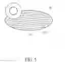
FIG. 7 is a simplified diagram showing how to dice the small prism array and place the small right angle prism mirrors in FIGS. 5-6 in accordance with an embodiment of the present invention.
FIGS. 8-13 are sectional diagrams illustrating sequential procedures of a method for fabricating small right angle prism mirrors in accordance with a second embodiment of the present invention
FIG. 14 is a simplified diagram showing how to dice the small prism array having the reflecting layer and place the small right angle prism mirrors in FIGS. 12-13 in accordance with an embodiment of the present invention.
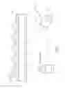
FIG. 15 is a simplified diagram of a projecting system in accordance with an embodiment of the present invention.
FIG. 16 is a simplified diagram of a projecting system in accordance with another embodiment of the present invention.
DETAILED DESCRIPTION
Certain terms are used throughout the following description and the claims to refer to particular system components. As one skilled in the art will appreciate, manufacturers may refer to a component by different names. This document does not intend to distinguish between components that differ in name but not function. In the following discussion and in the claims, the terms “include”, “including”, “comprise”, and “comprising” are used in an open-ended fashion, and thus should be interpreted to mean “including, but not limited to . . . ”.
Please refer to FIGS. 1-6. FIGS. 1-6 are sectional diagrams illustrating sequential procedures of a method for fabricating small right angle prism mirrors in accordance with a first embodiment of the present invention, wherein the small right angle prism mirrors can be utilized in an electronic system such as a small projector (e.g. portable projecting device). As shown in FIG. 1, a first step of the method in the present invention is coating a reflecting layer 102 on a top surface of a glass substrate 100, wherein the glass substrate 100 can be an optical wafer, and the reflecting layer 102 can be a mirror layer.
Next, as shown in FIG. 2, a second step of the method in the present invention is flipping the glass substrate 100 and forming an optical glue layer 104 on a bottom surface of the glass substrate 100, and providing a mold 106, wherein the mold 106 can be a soft mold.
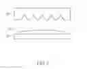
Next, as shown in FIG. 3, a third step of the method in the present invention is utilizing the mold 106 to form a 3D shape on the optical glue layer 104 and exposing the optical glue layer 104 having the 3D shape to solidify the optical glue layer 104 having the 3D shape and combine the glass substrate 100 having the reflecting layer 102 and the optical glue layer 104 having the 3D shape by using an ultraviolet (UV) light, wherein the optical glue layer comprises a UV glue material. In addition, the 3D shape can comprise a plurality of triangular prisms or a plurality of pyramids, wherein the pyramids can be triangular pyramids, square based pyramids, pentagonal pyramids, or hexagonal pyramids, etc.
Next, as shown in FIG. 4, a fourth step of the method in the present invention is removing the mold 106 to form a small prism array 108. Next, as shown in FIG. 5, a fifth step of the method in the present invention is dicing the small prism array 108 to generate a plurality of small right angle prism mirrors 110. Finally, as shown in FIG. 6, the small right angle prism mirrors 110 can be picked and placed for assembling electronic systems such as small projectors.
In addition, please refer to FIG. 7. FIG. 7 is a simplified diagram showing how to dice the small prism array 108 and place the small right angle prism mirrors 110 in accordance with an embodiment of the present invention. In this way, the present invention can use a semiconductor process such as an imprint process to fabricate the right angle prism mirrors having very small sizes and high quality without high cost. Please note that the above embodiment is merely for an illustrative purpose and is not meant to be a limitation of the present invention. For example, the 3D shape of the optical glue layer 104 and the number of the small right angle prism mirrors 110 can be changed according to different design requirements.
Please refer to FIGS. 8-13. FIGS. 8-13 are sectional diagrams illustrating sequential procedures of a method for fabricating small right angle prism mirrors in accordance with a second embodiment of the present invention, wherein the small right angle prism mirrors can be utilized in an electronic system such as a small projector (e.g. portable projecting device). As shown in FIG. 8, a first step of the method in the present invention is forming an optical glue layer 202 on a glass substrate 200 forming an optical glue layer on a glass substrate, and providing a mold 204, wherein the glass substrate 200 can be an optical wafer and the mold 204 can be a soft mold.
Next, as shown in FIG. 9, a second step of the method in the present invention is utilizing the mold 204 to form a 3D shape on the optical glue layer 202 and exposing the optical glue layer 202 having the 3D shape to solidify the optical glue layer 202 having the 3D shape and combine the glass substrate 200 having the reflecting layer 208 and the optical glue layer 202 having the 3D shape by using an ultraviolet (UV) light, wherein the optical glue layer comprises a UV glue material. In addition, the 3D shape can comprise a plurality of triangular prisms or a plurality of pyramids, wherein the pyramids can be triangular pyramids, square based pyramids, pentagonal pyramids, or hexagonal pyramids, etc.
Next, as shown in FIG. 10, a third step of the method in the present invention is removing the mold 204 to form a small prism array 206. Next, as shown in FIG. 11, a fourth step of the method in the present invention is coating a reflecting layer 208 on a top surface of the small prism array 206, wherein the reflecting layer 208 can be a mirror layer.
Next, as shown in FIG. 12, a fifth step of the method in the present invention is dicing the small prism array 206 having the reflecting layer 208 to generate a plurality of small right angle prism mirrors 210. Finally, as shown in FIG. 13, the small right angle prism mirrors 210 can be picked and placed for assembling electronic systems such as small projectors.
In addition, please refer to FIG. 14. FIG. 14 is a simplified diagram showing how to dice the small prism array 206 having the reflecting layer 208 and place the small right angle prism mirrors 210 in accordance with an embodiment of the present invention. In this way, the present invention can use a semiconductor process such as an imprint process to fabricate the right angle prism mirrors having very small sizes and high quality without high cost. Please note that the above embodiment is merely for an illustrative purpose and is not meant to be a limitation of the present invention. For example, the 3D shape of the optical glue layer 202 and the number of the small right angle prism mirrors 210 can be changed according to different design requirements.
Please refer to FIG. 15 and FIG. 16. FIG. 15 is a simplified diagram of a projecting system 300 in accordance with an embodiment of the present invention. FIG. 16 is a simplified diagram of a projecting system 400 in accordance with another embodiment of the present invention, wherein the projecting systems 300 and 400 can be small projectors (e.g. portable projecting devices). As shown in FIG. 15, the projecting system 300 comprises: a substrate 302, a light source 304, and a small right angle prism mirror 110 mentioned above. The light source 304 is disposed on the substrate 302, and utilized for emitting a light, wherein the light source 304 can be a laser. The small right angle prism mirror 110 is disposed on the substrate 302. The small right angle prism mirror 110 comprises: a solidified optical glue layer 104, a glass substrate 100, and a reflecting layer 102. The solidified optical glue layer 104 has a 3D shape with a bottom surface for fixed on the substrate 302, wherein there can be an adhesive layer 306 between the bottom surface of the 3D shape and the substrate 302. The glass substrate 100 is disposed on the solidified optical glue layer 104, and the reflecting layer 102 is disposed on the glass substrate 100, for reflecting the light from the light source 304.
As shown in FIG. 16, the projecting system 400 comprises: a substrate 402, a light source 404, and a small right angle prism mirror 210 mentioned above. The light source 404 is disposed on the substrate 402, and utilized for emitting a light, wherein the light source 404 can be a laser. The small right angle prism mirror 210 is disposed on the substrate 402. The small right angle prism mirror 210 comprises: a glass substrate 200, a solidified optical glue layer, 202 and a reflecting layer 208. The glass substrate 200 is utilized for fixed on the substrate 402, wherein there can be an adhesive layer 406 between the glass substrate 200 and the substrate 402. The solidified optical glue layer 202 is disposed on the glass substrate 200, and has a 3D shape. The reflecting layer 208 is disposed on a top surface of the solidified optical glue layer 202, and has a specific inclined plane for reflecting a light from the light source 404.
Briefly summarized, the present invention can use a semiconductor process such as an imprint process to fabricate the right angle prism mirrors having very small sizes and high quality without high cost, and apply the small right angle prism mirrors in the projecting system.
Those skilled in the art will readily observe that numerous modifications and alterations of the device and method may be made while retaining the teachings of the invention. Accordingly, the above disclosure should be construed as limited only by the metes and bounds of the appended claims.
Claims
What is claimed is:1. A method for fabricating small right angle prism mirrors, comprising:
coating a reflecting layer on a top surface of a glass substrate;
forming an optical glue layer on a bottom surface of the glass substrate;
utilizing a mold to form a 3D shape on the optical glue layer;
exposing the optical glue layer having the 3D shape to solidify the optical glue layer having the 3D shape and combine the glass substrate having the reflecting layer and the optical glue layer having the 3D shape;
removing the mold to form a small prism array; and
dicing the small prism array to generate a plurality of small right angle prism mirrors.
2. The method of claim 1, wherein the glass substrate is an optical wafer.
3. The method of claim 1, wherein the optical glue layer comprises an ultraviolet (UV) glue material.
4. The method of claim 1, wherein the 3D shape comprises a plurality of triangular prisms or a plurality of pyramids.
5. A small right angle prism mirror, comprising:
a solidified optical glue layer, having a 3D shape with a bottom surface for fixed on a substrate of an electronic system;
a glass substrate, disposed on the solidified optical glue layer; and
a reflecting layer, disposed on the glass substrate, for reflecting a light from a light source.
6. The right angle prism mirror of claim 5, wherein the glass substrate is an optical wafer.
7. The right angle prism mirror of claim 5, wherein the optical glue layer comprises a UV glue material.
8. The right angle prism mirror of claim 5, wherein the 3D shape comprises a triangular prism or a pyramid.
9. The right angle prism mirror of claim 5, wherein the electronic system is a projector.
10. A method for fabricating small right angle prism mirrors, comprising:
forming an optical glue layer on a glass substrate;
utilizing a mold to form a 3D shape on the optical glue layer;
exposing the optical glue layer having the 3D shape to solidify the optical glue layer having the 3D shape and combine the glass substrate having the reflecting layer and the optical glue layer having the 3D shape;
removing the mold to form a small prism array;
coating a reflecting layer on a top surface of the small prism array; and
dicing the small prism array having the reflecting layer to generate a plurality of small right angle prism mirrors.
11. The method of claim 10, wherein the glass substrate is an optical wafer.
12. The method of claim 10, wherein the optical glue layer comprises a UV glue material.
13. The method of claim 10, wherein the 3D shape comprises a plurality of triangular prisms or a plurality of pyramids.
14. A small right angle prism mirror, comprising:
a glass substrate, for fixed on a substrate of an electronic system;
a solidified optical glue layer, disposed on the glass substrate, having a 3D shape; and
a reflecting layer, disposed on a top surface of the solidified optical glue layer, having a specific inclined plane for reflecting a light from a light source.
15. The right angle prism mirror of claim 14, wherein the glass substrate is an optical wafer.
16. The right angle prism mirror of claim 14, wherein the optical glue layer comprises a UV glue material.
17. The right angle prism mirror of claim 14, wherein the 3D shape comprises a triangular prism or a pyramid.
18. The right angle prism mirror of claim 14, wherein the electronic system is a projector.
19. A projecting system, comprising:
a substrate;
a light source, disposed on the substrate, for emitting a light; and
a small right angle prism mirror, disposed on the substrate, comprising a solidified optical glue layer, a glass substrate, and a reflecting layer.
20. The right angle prism mirror of claim 19, wherein the solidified optical glue layer has a 3D shape with a bottom surface for fixed on the substrate, the glass substrate is disposed on the solidified optical glue layer, and the reflecting layer is disposed on the glass substrate, for reflecting the light from the light source.
21. The right angle prism mirror of claim 19, wherein the glass substrate is fixed on the substrate, the solidified optical glue layer is disposed on the glass substrate and has a 3D shape, and the reflecting layer is disposed on a top surface of the solidified optical glue layer and has a specific inclined plane for reflecting the light from the light source.
Images & Drawings included:


Sources:
- United States Patent and Trademark Office - verify current appl. status at the USPTO↗
Recent applications in this class:
- » 20250254276 2025-08-07
PROJECTION VIDEO DISPLAY APPARATUS WITH VARIABLE LIGHT ADJUSTMENT FOR MULTI-SCREEN PROJECTION MODE - » 20250247506 2025-07-31
DISPLAY METHOD, PROJECTOR, AND RECORDING MEDIUM ON WHICH PROGRAM IS RECORDED - » 20250193352 2025-06-12
IMAGE PROCESSING APPARATUS, IMAGE PROCESSING METHOD, AND IMAGE PROCESSING PROGRAM - » 20250193351 2025-06-12
CONTROL METHOD, PROJECTOR, AND NON-TRANSITORY COMPUTER-READABLE STORAGE MEDIUM - » 20250142030 2025-05-01
SYSTEMS AND METHODS FOR SPATIAL AWARENESS OF A REFUSE VEHICLE - » 20250106367 2025-03-27
LCD PROJECTOR WITH MULTIPLE DISPLAY SCREENS AND LENSES - » 20250039344 2025-01-30
Operating method for multi-screen projection system - » 20250039343 2025-01-30
MULTI-SCREEN PROJECTION SYSTEM - » 20250016293 2025-01-09
INFORMATION PROCESSING APPARATUS, INFORMATION PROCESSING METHOD, AND INFORMATION PROCESSING PROGRAM - » 20240333885 2024-10-03
PROJECTION METHOD, PROJECTION SYSTEM, AND PROJECTOR
Recent applications for this Assignee:
- » 20250224835 2025-07-10
TOUCH DETECTION CIRCUIT - » 20250216974 2025-07-03
CASCADE TOUCH CONTROL SYSTEM - » 20250182662 2025-06-05
COMPENSATING CIRCUIT AND COMPENSATING METHOD FOR PIXEL DATA OF DISPLAY DEVICE - » 20250181153 2025-06-05
THREE-DIMENSIONAL DISPLAY SYSTEM, DRIVING CIRCUIT, AND DISPLAY METHOD - » 20250110590 2025-04-03
Signal processing method and related circuit having backup processing circuit - » 20250085764 2025-03-13
METHOD OF PERFORMING POWER SAVING CONTROL ON DISPLAY DEVICE AND RELATED DISPLAY DEVICE - » 20250060455 2025-02-20
3D structure sensing system - » 20240427863 2024-12-26
ANTI-SPOOFING AUTHENTICATION SYSTEM - » 20240422476 2024-12-19
Sound source localization system - » 20240356556 2024-10-24
Clock data recovery circuit