Camera lens
US20190227280A1
2019-07-25
16/100,329
2018-08-10
✅ Patent granted
US 10,642,001 B2
2020-05-05
-
-
Mohammed A Hasan
IPro, PLLC | Na Xu
2039-01-04
Abstract:
The present disclosure provides a camera lens which has good optical properties, is ultra-thin, and includes five lenses having a bright F-number of less than 2.05. The camera lens includes, from an object side to an image side, a first lens having a positive refractive power, a second lens having a negative refractive power, a third lens having a negative refractive power, a fourth lens having a positive refractive power and a fifth lens having a negative refractive power. The camera lens satisfies specified relational expressions.
Assignee:
- AAC ACOUSTIC TECHNOLOGIES (SHENZHEN) CO., LTD. 368 🇨🇳 Shenzhen, China
Applicant:
Interested in similar patents?
Get notified when new applications in this technology area are published.
Classification:
G02B27/0037 » CPC further
Optical systems or apparatus not provided for by any of the groups - for optical correction, e.g. distorsion, aberration with diffracting elements
G02B13/0045 » CPC main
Optical objectives specially designed for the purposes specified below; Miniaturised objectives for electronic devices, e.g. portable telephones, webcams, PDAs, small digital cameras characterised by the lens design having at least one aspherical surface having five or more lenses
G02B13/009 » CPC further
Optical objectives specially designed for the purposes specified below; Miniaturised objectives for electronic devices, e.g. portable telephones, webcams, PDAs, small digital cameras having zoom function
G02B27/00 IPC
Optical systems or apparatus not provided for by any of the groups -
G02B13/00 IPC
Optical objectives specially designed for the purposes specified below
G02B15/14 » CPC further
Optical objectives with means for varying the magnification by axial movement of one or more lenses or groups of lenses relative to the image plane for continuously varying the equivalent focal length of the objective
Description
CROSS-REFERENCE TO RELATED APPLICATIONS
The present application claims priority to Japanese Patent Application No. 2018-006966, filed on Jan. 19, 2018, the content of which is incorporated herein by reference in its entirety.
TECHNICAL FIELD
The present disclosure relates to a camera lens, and in particular to a camera lens which is suitable for use in a modular camera for a mobile phone, a WEB camera, or the like using a camera element such as a high-pixel CCD or CMOS, has good optical properties, is ultra-thin to the point that total track length (TTL)/image height (IH) is ≤1.50, and includes of five lenses having bright F-number (hereinafter referred to as Fno) of less than 2.05.
BACKGROUND
In recent years, various types of camera devices equipped with a camera element such as a CCD and CMOS and others have been widely used. Along with the development of miniature and high performance camera elements, the ultrathin camera lenses with good optical properties and bright Fno are needed.
The technology related to the camera lens composed of five ultrathin with good optical properties and bright Fno is being developed gradually. The camera lens is composed of five lenses, which are lined up from an object side in an order as follows: a first lens having a positive refractive power, a second lens having a negative refractive power, a third lens having a negative refractive power, a fourth lens having a positive refractive power and a fifth lens having a negative refractive power.
The camera lens disclosed in the embodiments 1, 3, 4, 5 of Patent Document 1 is the above-described camera lens constituted of five lenses. However, since the refractive power distribution of the third lens, the fourth lens and the fifth lens, the ratio between the focal length of the first lens and the focal length of the second lens, and the shape of the first lens are not sufficient, the brightness of Fno=2.25 is not sufficient.
The camera lens disclosed in the embodiments of Patent Document 2 is the above-described camera lens constituted of five lenses. However, since the refractive power distribution of the third lens is not sufficient, the brightness of Fno≥2.25 is not sufficient.
PRIOR ART DOCUMENTS
Patent Documents
- Patent Document 1: Japanese Patent Application Laid-Open No. 2015-072424;
- Patent Document 2: Japanese Patent Application Laid-Open No. 2015-060171.
BRIEF DESCRIPTION OF DRAWINGS
Many aspects of the exemplary embodiment can be better understood with reference to the following drawings. The components in the drawings are not necessarily drawn to scale, the emphasis instead being placed upon clearly illustrating the principles of the present disclosure. Moreover, in the drawings, like reference numerals designate corresponding parts throughout the several views.
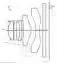
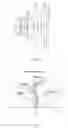
FIG. 1 is a structural diagram of a camera lens LA according to an embodiment of the present disclosure.
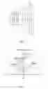
FIG. 2 is a structural diagram of the above-described camera lens LA according to Embodiment 1.
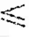
FIG. 3 is a diagram of a spherical aberration of the camera lens LA of Embodiment 1.
FIG. 4 is a diagram of a magnification chromatic aberration of the camera lens LA of Embodiment 1.
FIG. 5 is a diagram of field curvature and distortion of the camera lens LA of Embodiment 1.
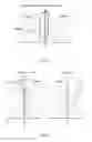
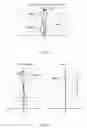
FIG. 6 is a structural diagram of the above-described camera lens LA according to Embodiment 2.
FIG. 7 is a diagram of a spherical aberration of the camera lens LA of Embodiment 2.
FIG. 8 is a diagram of a magnification chromatic aberration of the camera lens LA of Embodiment 2.
FIG. 9 is a diagram of field curvature and distortion of the camera lens LA of Embodiment 2.
DESCRIPTION OF EMBODIMENTS
An embodiment of a camera lens according to the present disclosure will be described with reference to the drawings. A diagram showing a structure of the camera lens according to the embodiment of the present disclosure is as shown in FIG. 1. The camera lens LA has a five-lens system which includes a first lens L1, a second lens L2, a third lens L3, a fourth lens L4 and a fifth lens L5, which are arranged from an object side toward an image side. A glass plate GF is provided between the fifth lens L5 and an imaging plane. The glass plate GF can be a glass plate using a cover glass or having an IR cut-off filter and other functions. In addition, the glass plate GF may not be provided between the fifth lens L5 and the imaging plane.
The first lens L1 is a lens having a positive refractive power, the second lens L2 is a lens having a negative refractive power, the third lens L3 is a lens having a negative refractive power, the fourth lens L4 is a lens having a positive refractive power, and the fifth Lens L5 is a lens having a negative refractive power. With respect to the lens surfaces of these five lenses, it is preferable to make them be aspheric surfaces in order to satisfactorily correct various aberrations.
The camera lens LA satisfies the following relational expressions (1) to (5):
−7.00<f3/f−3.50 (1),
0.80f4/f0.90 (2),
−0.80f5/f0.60 (3),
−4.00f2/f1−2.90 (4),
−2.00(R1+R2)/(R1−R2)−1.20 (5),
in which:
f denotes an overall focal length of the lens system,
f1 denotes a focal length of the first lens,
f2 denotes a focal length of the second lens,
f3 denotes a focal length of the third lens,
f4 denotes a focal length of the fourth lens,
f5 denotes a focal length of the fifth lens,
R1 denotes a curvature radius of an object side surface of the first lens, and
R2 denotes a curvature radius of an image side surface of the first lens.
The relational expression (1) specifies the negative refractive power of the third lens L3. When it is out of the range of the relational expression (1), it is not preferable because it is difficult to make the camera lens ultra-thin and have a bright Fno.
Furthermore, it is further preferable to set the numerical range of the relational expression (1) as the numerical range of the following relational expression (1-A):
−5.00f3/f−4.00 (1-A),
The relational expression (2) specifies the positive refractive power of the fourth lens L4. When it is out of the range of the relational expression (2), it is not preferable because it is difficult to make the camera lens ultra-thin and have a bright Fno.
Furthermore, it is further preferable to set the numerical range of the relational expression (2) as the numerical range of the following relational expression (2-A):
0.82 f4/f0.86 (2-A).
The relational expression (3) specifies the negative refractive power of the fifth lens L5. When it is out of the range of the relational expression (3), it is not preferable because it is difficult to make the camera lens ultra-thin and have a bright Fno.
Furthermore, it is further preferable to set the numerical range of the relational expression (3) as the numerical range of the following relational expression (3-A):
−0.785f5/f−0.74 (3-A).
The relational expression (4) specifies the ratio between the focal length of the first lens L1 and the focal length of the second lens L2. When it is out of the range of the relational expression (4), it is not preferable because it is difficult to make the camera lens ultra-thin and have a bright Fno.
Furthermore, it is further preferable to set the numerical range of the relational expression (4) as the numerical range of the following relational expression (4-A):
−3.40f2/f1−3.00 (4-A).
The relational expression (5) specifies the shape of the first lens L1. When it is out of the range of the relational expression (5), it is not preferable because it is difficult to make the camera lens ultra-thin and have a bright Fno.
Furthermore, it is further preferable to set the numerical range of the relational expression (5) as the numerical range of the following relational expression (5-A):
−1.50(R1+R2)/(R1−R2)−1.30 (5-A).
The fourth lens L4 is a lens having a positive refractive power, and satisfies the following relational expression (6):
0.18d7/f0.30 (6),
wherein
f denotes the overall focal length of the lens system,
d7 denotes the center thickness of the fourth lens.
The relational expression (6) specifies the ratio between the center thickness of the fourth lens L4 and the overall focal length f of the lens system. When it is out of the range of the relational expression (6), it is not preferable because it is difficult to make the camera lens ultra-thin and have a bright Fno.
Furthermore, it is further preferable to set the numerical range of the relational expression (6) as the numerical range of the following relational expression (6-A):
0.20d7/f0.25 (6-A).
The first lens L1 is a lens having a positive refractive power, and satisfies the following relational expression (7):
0.75f1/f0.85 (7),
wherein
f denotes the overall focal length of the lens system,
f1 denotes the focal length of the first lens.
The relational expression (7) specifies the positive refractive power of the first lens L1. When it is out of the range of the relational expression (7), it is not preferable because it is difficult to make the camera lens ultra-thin and have a bright Fno.
Furthermore, it is further preferable to set the numerical range of the relational expression (7) as the numerical range of the following relational expression (7-A):
0.80f1/f0.85 (7-A).
Each of the five lenses constituting the camera lens LA satisfies the structure and relational expression described above, and it is possible to obtain a camera lens which has good optical properties, is ultra-thin, and has a bright Fno2.05.
EMBODIMENTS
f: the overall focal length of the camera lens LA;
f1: the focal length of the first lens L1;
f2: the focal length of the second lens L2;
f3: the focal length of the third lens L3;
f4: the focal length of the fourth lens L4;
f5: the focal length of the fifth lens L5;
Fno: F-number;
2ω: full image angle;
S1: aperture;
R: the curvature radius of the optical surface, which is the center curvature radius of the lens;
R1: the curvature radius of the object side surface of the first lens L1;
R2: the curvature radius of the image side surface of the first lens L1;
R3: the curvature radius of the object side surface of the second lens L2;
R4: the curvature radius of the image side surface of the second lens L2;
R5: the curvature radius of the object side surface of the third lens L3;
R6: the curvature radius of the image side surface of the third lens L3;
R7: the curvature radius of the object side surface of the fourth lens L4;
R8: the curvature radius of the image side surface of the fourth lens L4;
R9: the curvature radius of the object side surface of the fifth lens L5;
R10: the curvature radius of the image side surface of the fifth lens L5;
R11: the curvature radius of the object side surface of the glass plate GF;
R12: the curvature radius of the image side surface of the glass plate GF;
d: the center thickness of the lens or the distance between the lenses;
d0: the axial distance from the open aperture S1 to the object side surface of the first lens L1;
d1: the center thickness of the first lens L1;
d2: the axial distance from the image side surface of the first lens L1 to the object side surface of the second lens L2;
d3: the center thickness of the second lens L2;
d4: the axial distance from the image side surface of the second lens L2 to the object side surface of the third lens L3;
d5: the center thickness of the third lens L3;
d6: the axial distance from the image side surface of the third lens L3 to the object side surface of the fourth lens L4;
d7: the center thickness of the fourth lens L4;
d8: the axial distance from the image side surface of the fourth lens L4 to the object side surface of the fifth lens L5;
d9: the center thickness of the fifth lens L5;
d10: the axial distance from the image side surface of the fifth lens L5 to the object side surface of the glass plate GF;
d11: the center thickness of the glass plate GF;
d12: the axial distance from the image side surface of the glass plate GF to the imaging plane;
nd: the refractive index of line d;
nd1: the refractive index of line d of the first lens L1;
nd2: the refractive index of line d of the second lens L2;
nd3: the refractive index of line d of the third lens L3;
nd4: the refractive index of line d of the fourth lens L4;
nd5: the refractive index of line d of the fifth lens L5;
nd6: the refractive index of line d of the glass plate GF;
νd: the Abbe number;
ν1: the Abbe number of the first lens L1;
ν2: the Abbe number of the second lens L2;
ν3: the Abbe number of the third lens L3;
ν4: the Abbe number of the fourth lens L4;
ν5: the Abbe number of the fifth lens L5;
ν6: the Abbe number of the glass plate GF;
TTL: optical length (the axial distance from the object side surface of the first lens L1 to the imaging plane);
LB: the axial distance from the image side surface of the fifth lens L5 to the imaging plane (including the thickness of the glass plate GF); and
IH: image height.
y=(x2/R)/[1+{1−(k+1)(x2/R2)}1/2]+A4x4+A6x6+A8x8+A10x10A12x12+A14x14+A16x16 (8)
R is the axial curvature radius, k is the conic coefficient, and A4, A6, A8, A10, A12, A14, and A16 are aspheric coefficients.
For the sake of convenience, the aspheric surface represented by the relational expression (8) is used as an aspheric surface of each of the lenses. However, the present disclosure is not limited to the aspheric surface represented by the relational expression (8).
Embodiment 1
FIG. 2 is a structural diagram of the camera lens LA of Embodiment 1. Each of the first lens L1 to the fifth lens L5 constituting the camera lens LA of Embodiment 1 has a curvature radius of R of the object side and image side, a center thickness of the lens or a distance d between the lenses, a refractive index nd, and an Abbe number ν d as shown in Table 1, and a conic coefficient k and an aspheric coefficient as shown in Table 2.
| TABLE 1 | ||||
| R | d | nd | ν d | |
| S1 | ∞ | d0= | −0.240 | ||||
| R1 | 1.38630 | d1= | 0.557 | nd1 | 1.5439 | ν 1 | 55.95 |
| R2 | 10.06405 | d2= | 0.066 | ||||
| R3 | −9.83957 | d3= | 0.240 | nd2 | 1.6614 | ν 2 | 20.41 |
| R4 | 17.78592 | d4= | 0.344 | ||||
| R5 | 9.02368 | d5= | 0.235 | nd3 | 1.6614 | ν 3 | 20.41 |
| R6 | 4.88827 | d6= | 0.162 | ||||
| R7 | −5.84815 | d7= | 0.787 | nd4 | 1.5439 | ν 4 | 55.95 |
| R8 | −1.28960 | d8= | 0.475 | ||||
| R9 | 194.68379 | d9= | 0.360 | nd5 | 1.5439 | ν 5 | 55.95 |
| R10 | 1.39173 | d10= | 0.400 | ||||
| R11 | ∞ | d11= | 0.300 | nd6 | 1.5168 | ν 6 | 64.17 |
| R12 | ∞ | d12= | 0.338 | ||||
| TABLE 2 | ||
| conic coefficient | aspheric coefficient |
| k | A4 | A6 | A8 | A10 | A12 | A14 | A16 | |
| R1 | −3.4191E+00 | 1.2950E−01 | −2.8950E−02 | −1.1269E−01 | 3.8578E−01 | −5.9751E−01 | 4.5806E−01 | −1.8315E−01 |
| R2 | 0.0000E+00 | −6.4349E−02 | 1.8067E−01 | −2.3042E−01 | 1.5431E−01 | −8.2151E−01 | 1.3167E+00 | −6.3471E−01 |
| R3 | 0.0000E+00 | −9.7663E−03 | 4.6439E−01 | −1.0673E+00 | 1.3508E+00 | −1.2852E+00 | 1.0059E+00 | −3.7234E−01 |
| R4 | 1.7143E+02 | −6.5832E−02 | 3.7855E−01 | −7.9770E−01 | 1.5813E+00 | −2.6814E+00 | 2.5496E+00 | −9.5584E−01 |
| R5 | 2.1528E+01 | −4.1671E−01 | 1.5412E−01 | −1.2704E−01 | −3.3645E−01 | 7.5128E−01 | −1.5760E−01 | −2.1417E−01 |
| R6 | −3.4732E+01 | −3.0036E−01 | 9.6782E−02 | 1.2859E−01 | −2.6323E−01 | 2.6222E−01 | 7.3456E−02 | −1.0761E−01 |
| R7 | 1.7568E+01 | −4.2330E−02 | −2.3339E−02 | 2.7348E−01 | −3.0880E−01 | 2.0072E−01 | −6.7597E−02 | 1.7929E−02 |
| R8 | −1.6393E+00 | 2.4287E−02 | −6.3071E−02 | 1.5183E−01 | −9.3590E−02 | 2.4306E−02 | −2.7843E−03 | 1.0441E−04 |
| R9 | 0.0000E+00 | −4.2356E−01 | 4.7222E−01 | −3.2814E−01 | 1.4082E−01 | −3.4905E−02 | 4.5775E−03 | −2.4612E−04 |
| R10 | −1.0307E+01 | −1.7857E−01 | 1.4458E−01 | −7.7704E−02 | 2.5548E−02 | −5.0326E−03 | 5.4269E−04 | −2.4233E−05 |
Table 5 below shows the numerical values defined in Embodiments 1 and 2 and the numerical values corresponding to the parameters specified by the relational expressions (1) to (7).
As shown in Table 5, Embodiment 1 satisfies the relational expressions (1) to (7).
The spherical aberration of the camera lens LA of Embodiment 1 is as shown in FIG. 3, the magnification chromatic aberration of magnification thereof is as shown in FIG. 4, and the field curvature and the distortion are as shown in FIG. 5. Furthermore, the field curvature S in FIG. 5 is the field curvature for the sagittal imaging plane, and T is the field curvature for the meridianal imaging plane, and the same applies to Embodiment 2. As can be seen from FIGS. 3 to 5, the camera lens LA of Embodiment 1 has TTL/IH=1.469, is ultra-thin to Fno=2.0, has a bright Fno, and has good optical properties.
Embodiment 2
FIG. 6 is a structural diagram of the camera lens LA of Embodiment 2. Each of the first lens L1 to the fifth lens L5 constituting the camera lens LA of Embodiment 2 has a curvature radius of R of the object side and image side, a center thickness of the lens or a distance d between the lenses, a refractive index nd, and an Abbe number ν d as shown in Table 3, and a conic coefficient k and an aspheric coefficient as shown in Table 4.
| TABLE 3 | ||||
| R | d | nd | ν d | |
| S1 | ∞ | d0= | −0.240 | ||||
| R1 | 1.38025 | d1= | 0.576 | nd1 | 1.5439 | ν 1 | 55.95 |
| R2 | 9.88765 | d2= | 0.062 | ||||
| R3 | −8.69315 | d3= | 0.238 | nd2 | 1.6614 | ν 2 | 20.41 |
| R4 | 22.97631 | d4= | 0.348 | ||||
| R5 | 9.33632 | d5= | 0.237 | nd3 | 1.6614 | ν 3 | 20.41 |
| R6 | 4.71713 | d6= | 0.160 | ||||
| R7 | −5.95228 | d7= | 0.765 | nd4 | 1.5439 | ν 4 | 55.95 |
| R8 | −1.28295 | d8= | 0.504 | ||||
| R9 | 142.15790 | d9= | 0.349 | nd5 | 1.5439 | ν 5 | 55.95 |
| R10 | 1.38044 | d10= | 0.400 | ||||
| R11 | ∞ | d11= | 0.300 | nd6 | 1.5168 | ν 6 | 64.17 |
| R12 | ∞ | d12= | 0.309 | ||||
| TABLE 4 | ||
| conic coefficient | aspheric coefficient |
| k | A4 | A6 | A8 | A10 | A12 | A14 | A16 | |
| R1 | −3.3680E+00 | 1.3885E−01 | −2.5881E−02 | −1.1800E−01 | 3.8379E−01 | −5.9448E−01 | 4.6382E−01 | −1.8914E−01 |
| R2 | 0.0000E+00 | −7.7317E−02 | 1.8102E−01 | −2.1696E−01 | 1.5966E−01 | −8.2505E−01 | 1.3122E+00 | −6.2972E−01 |
| R3 | 0.0000E+00 | −2.4456E−02 | 4.7726E−01 | −1.0726E+00 | 1.3494E+00 | −1.2807E+00 | 1.0093E+00 | −3.7974E−01 |
| R4 | 4.6871E+02 | −3.3206E−02 | 3.3874E−01 | −7.8780E−01 | 1.5975E+00 | −2.6813E+00 | 2.5369E+00 | −9.6437E−01 |
| R5 | 3.3257E+01 | −4.1515E−01 | 1.6321E−01 | −1.3325E−01 | −3.4567E−01 | 7.5171E−01 | −1.5332E−01 | −2.2558E−01 |
| R6 | −4.3425E+01 | −2.9894E−01 | 1.0255E−01 | 1.3203E−01 | −2.6660E−01 | 2.6501E−01 | 6.9981E−02 | −1.0078E−01 |
| R7 | 1.7721E+01 | −4.2223E−02 | −2.3608E−02 | 2.7387E−01 | −3.0844E−01 | 2.0078E−01 | −8.7730E−02 | 1.7714E−02 |
| R8 | −1.6154E+00 | 2.4468E−02 | −6.2459E−02 | 1.5178E−01 | −9.3807E−02 | 2.4188E−02 | −2.8131E−03 | 1.0409E−04 |
| R9 | 0.0000E+00 | −4.2346E−01 | 4.7225E−01 | −3.2813E−01 | 1.4082E−01 | −3.4906E−02 | 4.5774E−03 | −2.4609E−04 |
| R10 | −8.9495E+00 | −1.7852E−01 | 1.4456E−01 | −7.7699E−02 | 2.5552E−02 | −5.0316E−03 | 5.4284E−04 | −2.4229E−05 |
As shown in Table 5, Embodiment 2 satisfies the relational expressions (1) to (7).
The spherical aberration of the camera lens LA of Embodiment 2 is as shown in FIG. 7, the magnification chromatic aberration of magnification thereof is as shown in FIG. 8, and the field curvature and the distortion are as shown in FIG. 9. As can be seen from FIGS. 7 to 9, the camera lens LA of Embodiment 2 has TTL/IH=1.464, is ultra-thin to Fno=2.00, has a bright Fno, and has good optical properties.
Table 5 shows the numerical values defined in the embodiments and the numerical values corresponding to the parameters specified by the relational expressions (1) to (7). Furthermore, the units of the numerical values shown in Table 5 are respectively 2ω)(°), f (mm), f1 (mm), f2 (mm), f3 (mm), f4 (mm), f5 (mm), TTL (mm), LB (mm), and IH (mm).
| TABLE 5 | |||
| Embodiment 1 | Embodiment 2 | Notes | |
| f3/f | −4.801 | −4.300 | Exp(1) |
| f4/f | 0.834 | 0.831 | Exp(2) |
| f5/f | −0.750 | −0.750 | Exp(3) |
| f2/f1 | −3.302 | −3.301 | Exp(4) |
| (R1 + R2)/(R1 − R2) | −1.320 | −1.324 | Exp(5) |
| d7/f | 0.229 | 0.224 | Exp(6) |
| f1/f | 0.841 | 0.842 | Exp(7) |
| Fno | 2.00 | 2.00 | |
| 2ω | 79.0 | 78.9 | |
| TIL/IH | 1.469 | 1.464 | |
| f | 3.437 | 3.423 | |
| f1 | 2.891 | 2.881 | |
| f2 | −9.546 | −9.508 | |
| f3 | −16.502 | −14.717 | |
| f4 | 2.867 | 2.843 | |
| f5 | −2.579 | −2.565 | |
| TTL | 4.264 | 4.248 | |
| LB | 1.038 | 1.009 | |
| IH | 2.902 | 2.902 | |
LIST OF REFERENCE NUMBERS
- LA: camera lens
- S1: open aperture
- L1: the first lens
- L2: the second lens
- L3: the third lens
- L4: the fourth lens
- L5: the fifth lens
- GF: glass plate
- R: the curvature radius of the optical surface, which is the center curvature radius of the lens
- R1: the curvature radius of the object side surface of the first lens L1
- R2: a curvature radius of the image side surface of the first lens L1
- R3: a curvature radius of the object side surface of the second lens L2
- R4: a curvature radius of the image side surface of the second lens L2
- R5: a curvature radius of the object side surface of the third lens L3
- R6: a curvature radius of the image side surface of the third lens L3
- R7: a curvature radius of the object side surface of the fourth lens L4
- R8: a curvature radius of the image side surface of the fourth lens L4
- R9: a curvature radius of the object side surface of the fifth lens L5
- R10: a curvature radius of the image side surface of the fifth lens L5
- R11: a curvature radius of the object side surface of the glass plate GF
- R12: a curvature radius of the image side surface of the glass plate GF
- d: the center thickness of the lens or the distance between the lenses
- d0: the axial distance from the open aperture S1 to the object side surface of the first lens L1
- d1: the center thickness of the first lens L1
- d2: the axial distance from the image side surface of the first lens L1 to the object side surface of the second lens L2
- d3: the center thickness of the second lens L2
- d4: the axial distance from the image side surface of the second lens L2 to the object side surface of the third lens L3
- d5: the center thickness of the third lens L3
- d6: the axial distance from the image side surface of the third lens L3 to the object side surface of the fourth lens L4
- d7: the center thickness of the fourth lens L4
- d8: the axial distance from the image side surface of the fourth lens L4 to the object side surface of the fifth lens L5
- d9: the center thickness of the fifth lens L5
- d10: the axial distance from the image side surface of the fifth lens L5 to the object side surface of the glass plate GF
- d11: the center thickness of the glass plate GF
- d12: the axial distance from the image side surface of the glass plate GF to the imaging plane
Claims
What is claimed is:1. A camera lens, comprising, from an object side to an image side:
a first lens having a positive refractive power;
a second lens having a negative refractive power;
a third lens having a negative refractive power; and
a fourth lens having a positive refractive power and a fifth lens having a negative refractive power,
wherein the camera lens satisfies the following relational expressions (1) to (5):
−7.00<f3/f−3.50 (1),
0.80f4/f0.90 (2),
−0.80f5/f0.60 (3),
−4.00f2/f1−2.90 (4),
−2.00(R1+R2)/(R1−R2)−1.20 (5), and
wherein
f denotes an overall focal length of the camera lens,
f1 denotes a focal length of the first lens,
f2 denotes a focal length of the second lens,
f3 denotes a focal length of the third lens,
f4 denotes a focal length of the fourth lens,
f5 denotes a focal length of the fifth lens,
R1 denotes a curvature radius of an object side surface of the first lens,
R2 denotes a curvature radius of an image side surface of the first lens, and
d7 denotes a center thickness of the fourth lens.
2. The camera lens according to claim 1, wherein:
the camera lens satisfies the following relational expression (6):
0.18d7/f0.30 (6).
3. The camera lens according to claim 1, wherein:
the camera lens satisfies the following relational expression (7):
0.75f1/f0.85 (7).
Images & Drawings included:
Sources:
- United States Patent and Trademark Office - verify current appl. status at the USPTO↗
Similar patent applications:
- » 20200150388
Camera lens processing method, camera lens, camera assembly and electronic device - » 20130250109
Multi-lens camera system, vehicle mounting the multi-lens camera system, and range-finding method executed by the multi-lens camera system - » 20210088757
Multi-lens camera lens, camera module, and terminal including a lens providing a diffractive surface concave to the image side plane - » 20240118459
MOTOR FOR DRIVING LIQUID STATE CAMERA LENS, CAMERA LENS ASSEMBLY, AND TERMINAL DEVICE - » 20180231737
Camera lens, camera and method of locking a focus ring in a camera lens - » 20240244309
CAMERA LENS MODULE, CAMERA LENS OPTICAL AXIS ADJUSTING DEVICE, AND BINOCULAR CAMERA - » 20190129073
CAMERA LENS AND CAMERA LENS ASSEMBLY HAVING SAME - » 20210352196
INTEGRATED LENS BARREL, OPTICAL CAMERA LENS, CAMERA MODULE AND ASSEMBLY METHOD THEREOF - » 20190243093
Camera lens assembly and camera device equipped with camera lens assembly - » 20180292628
Camera lens assembly and camera device equipped with camera lens assembly
Recent applications in this class:
- » 20250291158 2025-09-18
IMAGING OPTICAL LENS ASSEMBLY, IMAGING APPARATUS AND ELECTRONIC DEVICE - » 20250291157 2025-09-18
OPTICAL IMAGING LENS ASSEMBLY - » 20250284101 2025-09-11
OPTICAL SYSTEM AND IMAGE PICKUP APPARATUS - » 20250284100 2025-09-11
OPTICAL SYSTEM, IMAGING DEVICE, IN-VEHICLE SYSTEM, AND MOVABLE APPARATUS - » 20250284099 2025-09-11
OPTICAL IMAGING SYSTEM - » 20250284098 2025-09-11
LENS MODULE - » 20250284097 2025-09-11
OPTICAL SYSTEM, CAMERA MODULE, AND ELECTRONIC DEVICE - » 20250284096 2025-09-11
CAMERA OPTICAL LENS - » 20250284095 2025-09-11
CAMERA OPTICAL LENS - » 20250277961 2025-09-04
IMAGING LENS SYSTEM AND CAMERA MODULE
Recent applications for this Assignee:
- » 20250126386 2025-04-17
MEMS microphone - » 20250080917 2025-03-06
Speaker module and assembling method thereof - » 20250056163 2025-02-13
Sounding Device - » 20250042722 2025-02-06
MEMS microphone - » 20250039600 2025-01-30
SINGLE-END-TO-DIFFERENTIAL MICROPHONE CIRCUIT AND ELECTRONIC EQUIPMENT - » 20250038713 2025-01-30
Single-end-to-differential microphone circuit - » 20250024199 2025-01-16
Microphone amplifying circuit design method and microphone amplifying circuit - » 20240393821 2024-11-28
TRIGGER MODULE WITH FORCE FEEDBACK - » 20240284093 2024-08-22
Microphone module - » 20240219293 2024-07-04
Gas Sensor