SOLAR POWERED FAN
US20190237984A1
2019-08-01
15/885,833
2018-02-01
Abstract:
A solar powered fan, including a body, a fan rotatably disposed within and attached to the body, and a solar panel disposed on a surface of the body and connected to the fan to provide power to the fan, such that the fan rotates when the solar panel receives energy from the Sun.
Interested in similar patents?
Get notified when new applications in this technology area are published.
Classification:
H02J7/025 » CPC further
Circuit arrangements for charging or depolarising batteries or for supplying loads from batteries for charging batteries from ac mains by converters characterised by the type of converter using non-contact coupling, e.g. inductive, capacitive
H02J7/0068 » CPC main
Circuit arrangements for charging or depolarising batteries or for supplying loads from batteries Battery or charger load switching, e.g. concurrent charging and load supply
F04D25/0673 » CPC further
Pumping installations or systems; Units comprising pumps and their driving means the pump being electrically driven Battery powered
F04D25/08 » CPC further
Pumping installations or systems; Units comprising pumps and their driving means the working fluid being air, e.g. for ventilation
H02J7/0047 » CPC further
Circuit arrangements for charging or depolarising batteries or for supplying loads from batteries with monitoring or indicating devices or circuits
H02J7/00 IPC
Circuit arrangements for charging or depolarising batteries or for supplying loads from batteries
F04D25/06 IPC
Pumping installations or systems; Units comprising pumps and their driving means the pump being electrically driven
H02J7/02 IPC
Circuit arrangements for charging or depolarising batteries or for supplying loads from batteries for charging batteries from ac mains by converters
H02S99/00 » CPC further
Subject matter not provided for in other groups of this subclass
Description
BACKGROUND
1. Field
The present general inventive concept relates generally to a fan, and more particularly, to a solar powered fan.
2. Description of the Related Art
When having fun in the sun, sweat is unavoidable as the heat beats down on the skin. Having a mobile fan would be great, but unfortunately, most of them require an outlet for the cord to be plugged in to or if its battery operated, may not provide a strong motor to distribute a fresh breeze.
Therefore, there is a need for a battery-operated fan that is solar-powered.
SUMMARY
The present general inventive concept provides a solar powered fan.
Additional features and utilities of the present general inventive concept will be set forth in part in the description which follows and, in part, will be obvious from the description, or may be learned by practice of the general inventive concept.
The foregoing and/or other features and utilities of the present general inventive concept may be achieved by providing a solar powered fan, including a body, a fan rotatably disposed within and attached to the body, and a solar panel disposed on a surface of the body and connected to the fan to provide power to the fan, such that the fan rotates when the solar panel receives energy from the Sun.
The solar powered fan may further include a battery to provide power to the fan.
The solar panel may charge the battery.
The body may include at least one charging indicator to indicate whether the battery is being charged via at least one of the solar panel and a power cord jack connected to the battery.
BRIEF DESCRIPTION OF THE DRAWINGS
These and/or other features and utilities of the present generally inventive concept will become apparent and more readily appreciated from the following description of the embodiments, taken in conjunction with the accompanying drawings of which:
FIG. 1 illustrates a top angled view of a front portion of a solar powered fan, according to an exemplary embodiment of the present general inventive concept; and
FIG. 2 illustrates a top angled view of a rear portion of a solar powered fan, according to an exemplary embodiment of the present general inventive concept,
DETAILED DESCRIPTION OF THE INVENTION
Various example embodiments (a.k.a., exemplary embodiments) will now be described more fully with reference to the accompanying drawings in which some example embodiments are illustrated. In the figures, the thicknesses of lines, layers and/or regions may be exaggerated for clarity.
Accordingly, while example embodiments are capable of various modifications and alternative forms, embodiments thereof are shown by way of example in the figures and will herein be described in detail. It should be understood, however, that there is no intent to limit example embodiments to the particular forms disclosed, but on the contrary, example embodiments are to cover all modifications, equivalents, and alternatives falling within the scope of the disclosure. Like numbers refer to like/similar elements throughout the detailed description.
It is understood that when an element is referred to as being “connected” or “coupled” to another element, it can be directly connected or coupled to the other element or intervening elements may be present. In contrast, when an element is referred to as being “directly connected” or “directly coupled” to another element, there are no intervening elements present. Other words used to describe the relationship between elements should be interpreted in a like fashion (e.g., “between” versus “directly between,” “adjacent” versus “directly adjacent,” etc.).
The terminology used herein is for the purpose of describing particular embodiments only and is not intended to be limiting of example embodiments. As used herein, the singular forms “a,” “an” and “the” are intended to include the plural forms as well, unless the context clearly indicates otherwise. It will be further understood that the terms “comprises,” “comprising,” “includes” and/or “including,” when used herein, specify the presence of stated features, integers, steps, operations, elements and/or components, but do not preclude the presence or addition of one or more other features, integers, steps, operations, elements, components and/or groups thereof.
Unless otherwise defined, all terms (including technical and scientific terms) used herein have the same meaning as commonly understood by one of ordinary skill in the art to which example embodiments belong. It will be further understood that terms, e.g., those defined in commonly used dictionaries, should be interpreted as having a meaning that is consistent with their meaning in the context of the relevant art. However, should the present disclosure give a specific meaning to a term deviating from a meaning commonly understood by one of ordinary skill, this meaning is to be taken into account in the specific context this definition is given herein.
FIG. 1 illustrates a top angled view of a front portion of a solar powered fan 100, according to an exemplary embodiment of the present general inventive concept.
The solar powered fan 100 may include a body 110, a fan 120, a battery 130, a switch 140, and a solar panel 150.
The solar powered fan 100 may be constructed from plastic, wood, metal, rubber, silicone, glass, or any other material known to one of ordinary skill in the art.
The fan 120 may be disposed within the body 110, and may have a plurality of blades to provide a cooling sensation when the fan 120 rotates in a direction on a vertical axis, thereby propelling air in a direction perpendicular to the rotation direction of the fan 120.
The fan 120 may have a motor therein to allow the fan 120 to be mechanically rotated when connected to the battery 130.
The battery 130 may provide power to the fan 120, such that the fan 120 may rotate when the battery 130 maintains at least a small charge.
The switch 140 may be disposed on a surface of the body 110, and may be connected to the battery 130 to provide power to the fan 120 when the switch 140 is turned on.
The switch 140 may be a rotatable switch, a button, or a touch screen, but is not limited thereto.
The switch 140 may be rotated to turn the fan 120 on. More specifically, the switch 140 may be rotated to allow the battery 130 to provide power to the fan 120 such that the fan 120 may rotate. The further the switch 140 is rotated, the faster the fan 120 may correspondingly rotate.
The solar panel 150 may be disposed on any surface of the body 150, may have any size and shape, and may be connected to at least one of the battery 130 and the fan 120. More specifically, when the solar panel 150 is exposed to the Sun, the solar panel 150 may harness energy from the Sun to provide power to the fan 120 to cause the fan 120 to rotate. As such, the fan 120 may rotate even if the battery 130 is not charged.
Alternatively, the when the solar panel 150 is exposed to the Sun, the solar panel 150 may harness energy from the Sun to charge the battery 130.
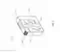
FIG. 2 illustrates a top angled view of a rear portion of the solar powered fan 100, according to an exemplary embodiment of the present general inventive concept.
The solar powered fan 100 may include, on a rear surface thereof, a power cord jack 160, first a charging indicator 170, and a second charging indicator 180
The power cord jack 160 may be connected to the battery 130, such that the battery 30 may be charged when the power cord jack 160 is connected to a electrical power outlet via a power cord.
The first charging indicator 170 may indicate that the battery 130 is being charged by a power cord via the power cord jack 160. More specifically, when the battery 130 is being charged via the power cord jack 160, a red light may indicate that the battery 130 has a low charge, a yellow light may indicate that the battery 130 is charging, and a green light may indicate that the battery 130 is fully charged. However, the indicator lights are not limited to these colors, and may be either solid or blinking lights. Alternatively, the first charging indicator 170 may be a screen that outputs numbers regarding an amount of charge retained by the battery 130.
The second charging indicator 170 may indicate that the battery 130 is being charged via the solar panel 150. More specifically, when the battery 130 is being charged via the solar panel 150, a red light may indicate that the battery 130 has a low charge, a yellow light may indicate that the battery 130 is charging, and a green light may indicate that the battery 130 is fully charged. However, the indicator lights are not limited to these colors, and may be either solid or blinking lights. Alternatively, the second charging indicator 180 may be a screen that outputs numbers regarding an amount of charge retained by the battery 130.
Although FIG. 2 illustrates separate first and second charging indicators 170 and 180, respectively, the present general inventive concept may include a single charging indicator, or multiple charging indicators, disposed anywhere on the body 110.
Although a few embodiments of the present general inventive concept have been shown and described, it will be appreciated by those skilled in the art that changes may be made in these embodiments without departing from the principles and spirit of the general inventive concept, the scope of which is defined in the appended claims and their equivalents.
Claims
1. A solar powered fan, comprising:
a body;
a fan rotatably disposed within and attached to the body; and
a solar panel disposed on a surface of the body and connected to the fan to provide power to the fan, such that the fan rotates when the solar panel receives energy from the Sun.
2. The solar powered fan of claim 1, further comprising:
a battery to provide power to the fan.
3. The solar powered fan of claim 2, wherein the solar panel charges the battery.
4. The solar powered fan of claim 1, wherein the body comprises:
at least one charging indicator to indicate whether the battery is being charged via at least one of the solar panel and a power cord jack connected to the battery.
Images & Drawings included:


Sources:
- United States Patent and Trademark Office - verify current appl. status at the USPTO↗
Similar patent applications:
- » 20150087216
SOLAR-POWERED FAN FOR A RECREATION VEHICLE AND SOLAR-POWERED, FAN EQUIPPED VENT COVER THAT FITS ON TOP OF A RECREATIONAL VEHICLE ROOF VENT - » 20160221418
SOLAR-POWERED FAN FOR A RECREATION VEHICLE AND SOLAR-POWERED, VENT COVER THAT FITS ON TOP OF A RECREATIONAL VEHICLE ROOF HAVING A FAN - » 20120178357
SOLAR-POWERED FAN THAT FITS INSIDE NEW AND/OR EXISTING ROOF VENTS - » 20070129002
Solar powered fan for portable enclosure - » 20080152482
Solar powered fan - » 20200370770
DUAL FAN, SOLAR POWERED VENTILATION SYSTEM FOR PORTABLE TOILET ENCLOSURES AND METHOD OF USE - » 20120302154
Solar powered vent fan system and kit of parts - » 20110217194
Solar-powered soffit fan - » 20150300196
Solar powered compressor fan driven turbine grid scale electricity generation system - » 20160010886
Concealed Housing For A Solar Powered Attic Fan
Recent applications in this class:
- » 20250175024 2025-05-29
ULTRACAPACITOR MODULE WITH AUTONOMOUS SELF LEARNING - » 20250167574 2025-05-22
CHARGING AND DISCHARGING DEVICE AND METHOD FOR CONTROLLING CHARGING AND DISCHARGING - » 20250141253 2025-05-01
PROCESSING APPARATUS OF BATTERY PACK AND ELECTRONIC DEVICE - » 20250132586 2025-04-24
POWER SYSTEM - » 20250105645 2025-03-27
ENERGY STORAGE EQUIPPED SAFETY SYSTEM AND METHOD - » 20250105644 2025-03-27
METHOD AND SYSTEM FOR BLACKOUT PREVENTION ON A DRILLING RIG - » 20250079867 2025-03-06
POWER SUPPLY UNIT FOR AEROSOL GENERATION DEVICE - » 20250079866 2025-03-06
ENERGY STORAGE DEVICE, METHOD FOR ENERGY STORAGE DEVICE TO DETERMINE WHETHER CONVERTER DEVICE CONNECTED THERETO HAS NEUTRAL LINE, AND POWER SUPPLY SYSTEM - » 20250079865 2025-03-06
CHARGING SYSTEMS AND ASSOCIATED METHODS - » 20250070581 2025-02-27
BATTERY PACK