Tire tread
US20190263186A1
2019-08-29
15/903,060
2018-02-23
✅ Patent granted
US 10,807,416 B2
2020-10-20
-
-
Steven D Maki
Robert N. Lipcsik
2038-09-08
Abstract:
A tread includes a plurality of circumferential grooves. Each of the plurality extends continuously in a tire circumferential direction. The plurality of circumferential grooves defining a circumferentially extending main rib and a circumferentially extending curtain rib axially separated by a curtain groove. The curtain groove having an axial width between 4% and 40% of a minimum axial width of a main groove of the plurality of circumferential grooves. The main groove is disposed axially opposite the curtain groove and adjacent to the curtain rib.
Assignee:
- THE GOODYEAR TIRE & RUBBER COMPANY 1,409 🇺🇸 Akron, OH, United States
Applicant:
Interested in similar patents?
Get notified when new applications in this technology area are published.
Classification:
B60C11/0304 » CPC main
Tyre tread bands; Tread patterns; Anti-skid inserts; Tread patterns Asymmetric patterns
B60C11/0302 » CPC further
Tyre tread bands; Tread patterns; Anti-skid inserts; Tread patterns directional pattern, i.e. with main rolling direction
B60C11/0309 » CPC further
Tyre tread bands; Tread patterns; Anti-skid inserts; Tread patterns; Patterns comprising block rows or discontinuous ribs further characterised by the groove cross-section
B60C11/04 » CPC further
Tyre tread bands; Tread patterns; Anti-skid inserts; Tread patterns in which the raised area of the pattern consists only of continuous circumferential ribs, e.g. zig-zag
B60C11/12 » CPC further
Tyre tread bands; Tread patterns; Anti-skid inserts; Tread patterns characterised by the use of narrow slits or incisions, e.g. sipes
B60C11/13 » CPC further
Tyre tread bands; Tread patterns; Anti-skid inserts; Tread patterns characterised by the groove cross-section, e.g. for buttressing or preventing stone-trapping
B60C11/1307 » CPC further
Tyre tread bands; Tread patterns; Anti-skid inserts; Tread patterns characterised by the groove cross-section, e.g. for buttressing or preventing stone-trapping with special features of the groove walls
B60C11/1323 » CPC further
Tyre tread bands; Tread patterns; Anti-skid inserts; Tread patterns characterised by the groove cross-section, e.g. for buttressing or preventing stone-trapping with special features of the groove walls asymmetric
B60C2011/0348 » CPC further
Tyre tread bands; Tread patterns; Anti-skid inserts; Tread patterns characterised by particular design features of the pattern; Grooves; Circumferential grooves Narrow grooves, i.e. having a width of less than 4 mm
B60C2011/0353 » CPC further
Tyre tread bands; Tread patterns; Anti-skid inserts; Tread patterns characterised by particular design features of the pattern; Grooves; Circumferential grooves characterised by width
B60C2011/0381 » CPC further
Tyre tread bands; Tread patterns; Anti-skid inserts; Tread patterns characterised by particular design features of the pattern; Grooves Blind or isolated grooves
B60C2011/0383 » CPC further
Tyre tread bands; Tread patterns; Anti-skid inserts; Tread patterns characterised by particular design features of the pattern; Grooves; Blind or isolated grooves at the centre of the tread
B60C2011/0388 » CPC further
Tyre tread bands; Tread patterns; Anti-skid inserts; Tread patterns characterised by particular design features of the pattern; Continuous ribs provided at the equatorial plane
B60C2011/0393 » CPC further
Tyre tread bands; Tread patterns; Anti-skid inserts; Tread patterns characterised by particular design features of the pattern; Continuous ribs Narrow ribs, i.e. having a rib width of less than 8 mm
B60C2200/04 » CPC further
Tyres specially adapted for particular applications for road vehicles, e.g. passenger cars
B60C11/03 IPC
Tyre tread bands; Tread patterns; Anti-skid inserts Tread patterns
Description
FIELD OF THE INVENTION
The present invention relates to a pneumatic tire that exhibits excellent noise performance while maintaining wet performance.
BACKGROUND OF THE PRESENT INVENTION
Conventionally, in addition to circumferential main grooves and lateral grooves, pneumatic tire treads may have sipes on a tread surface in order to demonstrate favorable functional characteristics (e.g., low noise generation, low rolling resistance, good traction, good durability, etc.).
SUMMARY OF THE INVENTION
A tread in accordance with the present invention includes a plurality of circumferential grooves. Each of the plurality extends continuously in a tire circumferential direction. The plurality of circumferential grooves defining a circumferentially extending main rib and a circumferentially extending curtain rib axially separated by a curtain groove. The curtain groove having an axial width between 4% and 40% of a minimum axial width of a main groove of the plurality of circumferential grooves. The main groove is disposed axially opposite the curtain groove and adjacent to the curtain rib.
According to another aspect of the tread, the curtain groove has a radial depth less than or equal to the main groove.
According to still another aspect of the tread, the axial width of the curtain groove narrows as the curtain groove extends radially inward.
According to yet another aspect of the tread, the curtain rib has a uniform axial width between 0.5 mm and 3.5 mm.
According to still another aspect of the tread, the curtain rib has a uniform axial width of about 2.0 mm.
According to yet another aspect of the tread, the main rib has a circumferential array of axially extending lateral grooves, the lateral grooves extending from one of the plurality of circumferential grooves other than the main groove.
According to still another aspect of the tread, one end of each of the lateral grooves joins the curtain groove.
According to yet another aspect of the tread, one end of the lateral grooves intersects with the curtain groove.
According to still another aspect of the tread, the curtain groove tapers radially inward to an axial width between 0.2 mm and 0.5 mm.
According to yet another aspect of the tread, the curtain groove tapers radially inward to an axial width less than an axial width of the curtain groove at an outer surface of the tread.
A tire tread in accordance with the present invention includes a plurality of annular grooves. Each of the plurality extends continuously in a tire circumferential direction. The plurality of annular grooves defines a circumferentially extending main rib and a circumferentially extending curtain rib axially separated by a curtain groove. The curtain groove has an axial width between 4% and 10% of a minimum axial width of a main groove of the plurality of annular grooves. The main groove is located axially opposite the curtain groove and axially adjacent to the curtain rib.
According to another aspect of the tire tread, the curtain groove has a radial depth equal to the main groove.
According to still another aspect of the tire tread, the axial width of the curtain groove narrows as the curtain groove extends radially inward.
According to yet another aspect of the tire tread, the curtain rib has an axial width between 1.0 mm and 2.0 mm.
According to still another aspect of the tire tread, the curtain rib has an axial width of about 1.0 mm.
According to yet another aspect of the tire tread, the main rib has a circumferential array of axially extending lateral grooves, the lateral grooves extending from one of the plurality of circumferential grooves other than the main groove.
According to still another aspect of the tire tread, one end of each of the lateral grooves joins the curtain groove.
According to yet another aspect of the tire tread, one end of the lateral grooves intersects with the curtain groove.
According to still another aspect of the tire tread, the curtain groove tapers radially inward to an axial width between 0.5 mm and 0.7 mm.
According to yet another aspect of the tire tread, the curtain groove tapers radially inward to an axial width less than an axial width of the curtain groove at an outer surface of the tread.
BRIEF DESCRIPTION OF THE DRAWINGS
A more complete appreciation of the present invention and many of the attendant advantages thereof will be readily ascertained as the same becomes better understood by reference to the following detailed description when considered in connection with the accompanying drawings, wherein:
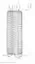
FIG. 1 schematically shows an orthogonal front view of an example tire tread in accordance with the present invention;
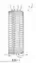
FIG. 2 schematically shows a detail view of part of the tire tread of FIG. 1; and
FIG. 3 schematically shows a section view taken along line 3-3 in FIG. 2.
DETAILED DESCRIPTION OF THE EXAMPLES OF THE PRESENT INVENTION
Examples of the present invention may be below described with reference to the accompanying drawings, wherein like reference numerals designate corresponding and/or identical elements throughout FIGS. 1-3.
As shown in FIGS. 1-2, an example non-pneumatic or pneumatic tire 1 according to the present invention (hereinafter may be referred to simply as “tire”) may be a tire mounted in a designated direction on a vehicle. The right side of the tire 1 in FIG. 1 may be set as the outer side when it is mounted on a vehicle. The tire 1 may be asymmetrical about a tire equator C. The tire 1 may be used for a passenger car, for example.
A tread 2 of tire 1 may have a pair of shoulder grooves 3, 4 and a pair of intermediate grooves 5, 6. The shoulder grooves 3, 4 may be positioned on each side of tire equator C and closest to either footprint edge Te, Te extending continuously in a circumferential direction. The shoulder and intermediate grooves 3, 4, 5, 6 may extend circumferentially and linearly in a straight line at a substantially constant groove width.
The grooves 3, 4, 5, 6 may define five circumferentially extending ribs of tread elements: a center rib 11, a pair of intermediate ribs 13, 15, and a pair of shoulder ribs 17, 19. Each rib 11, 13, 15, 17, 19 may be spaced from an adjacent row by the circumferentially continuous grooves 3, 4, 5, 6.
The tread elements 131 of the first intermediate rib 13 may define a circumferential array of spaced apart downwardly angled lateral grooves 132 extending from the first shoulder groove 3 toward the first intermediate groove 5. The continuous center rib 11 may have a circumferential array of widely spaced apart downwardly angled blind lateral grooves 112 extending at a downward angle from the first intermediate groove 5. The continuous second intermediate rib 15 may have a circumferential array of widely spaced apart shorter blind lateral grooves 152 extending from the second intermediate groove 6. The tread elements 171 of the first shoulder rib 17 may define a circumferential array of downwardly arched lateral grooves 172 extending from the outer edge Te to the first shoulder groove 3. The tread elements 191 of the second shoulder rib 19 may define a circumferential array of upwardly arched lateral grooves 192 extending from the outer edge Te to the first shoulder groove 4. Various other sipes 9 may be located across the ribs 11, 13, 15, 17, 19 of the tread 2, as specifically shown in FIG. 2.
FIG. 3 shows a cross-sectional view taken at “3-3” in FIG. 2. In accordance with the present invention, the example tread 2 may further define a circumferentially extending rib, or curtain 101, coupled with one or more or all of the ribs 11, 13, 15, 19 for reducing airborne/exterior noise propagation of the tread during rotation of the tire 1 under load. The curtain 101 may be coupled to the rib 11, 13, 15, 17, and/or 19. In the example tire 1 and tread 2 of FIGS. 1-3, a narrow curtain 101 and the first intermediate rib 13 are coupled by a narrow circumferential curtain groove 102. The curtain 101 may be the same radial height as the first intermediate rib 13 and have a uniform axial width between 0.5 mm and 3.5 mm or 0.5 mm and 1.5 mm. The axial width of the of the curtain groove 102 at an outer surface 103 of the tread 2 may be between 0.5 mm and 3.5 mm. As the curtain groove 102 extends radially inward, the axial width may lessen, or taper, to an axial width between 0.5 mm and 0.2 mm (FIG. 3). The radial depth of the curtain groove 102 may be less than or equal to the radial depth of the first intermediate groove 5 or the corresponding circumferential groove 3, 4, 5, and/or 6. The circumferential grooves 3, 4, 5, 6 may have minimum axial widths between 4.0 mm and 16.0 mm Thus, the axial width of the curtain groove 102 may be between 4% and 20% or 4% and 40% the minimum axial width of the first intermediate groove 5.
In one set of examples, the axial width of the curtain groove 102 at the outer surface 103 of the tread 2 may be 1.0 mm tapering to a 0.3 mm axial width at the radially innermost end of the curtain groove and the minimum axial width of the first intermediate groove 5 may be 5.0 mm, 11.0 mm, or 7.0 mm. In these examples, the axial width of the curtain groove 102 may be 20%, 9%, or 14% the minimum axial width of the first intermediate groove 5.
In another set of examples, the axial width of the of the curtain groove 102 at the outer surface 103 of the tread 2 may be 1.0 mm tapering to a 0.3 mm axial width at the radially innermost end of the curtain groove and the minimum axial width of the first intermediate groove 5 may be 5.1 mm, 10.8 mm, or 6.7 mm. In these examples, the axial width of the curtain groove 102 may be approximately 20%, 9%, or 15% the minimum axial width of the first intermediate groove 5.
In the example of FIGS. 1-3, the lateral grooves 132 of the first intermediate rib 13 may extend and join the curtain groove 102 in order to further suppress noise propagation. These examples of a narrow curtain 101 and a narrow curtain groove 102 thereby advantageously have very little, if any, effect on other tire characteristics, such as handling, wear, rolling resistance, and/or traction. Further, the addition of the curtain groove 102 may only lessen tire weight and material costs.
So far, a tire according to the present invention has been described in detail. However, the present invention is not limited to the above examples, and various modifications of the example may also apply. Numerous modifications and variations of the present invention are possible in light of the above teachings. It is therefore to be understood that within the scope of the appended claims, the present invention may be practiced otherwise than as specifically and exemplarily described herein.
Claims
What is claimed:1. A tire tread comprises:
a plurality of circumferential grooves, each of the plurality extending continuously in a tire circumferential direction,
the plurality of circumferential grooves defining a circumferentially extending main rib and a circumferentially extending curtain rib axially separated by a curtain groove, the curtain groove having an axial width between 4% and 40% of a minimum axial width of a main groove of the plurality of circumferential grooves, the main groove being disposed axially opposite the curtain groove and adjacent to the curtain rib.
2. The tire as set forth in claim 1 wherein the curtain groove has a radial depth less than or equal to the main groove.
3. The tire as set forth in claim 1 wherein the axial width of the curtain groove narrows as the curtain groove extends radially inward.
4. The tire as set forth in claim 1 wherein the curtain rib has a uniform axial width between 0.5 mm and 3.5 mm.
5. The tire as set forth in claim 1 wherein the curtain rib has a uniform axial width of about 2.0 mm.
6. The tire as set forth in claim 1 wherein the main rib has a circumferential array of axially extending lateral grooves, the lateral grooves extending from one of the plurality of circumferential grooves other than the main groove.
7. The tire as set forth in claim 6 wherein one end of each of the lateral grooves joins the curtain groove.
8. The tire as set forth in claim 6 wherein one end of the lateral grooves intersects with the curtain groove.
9. The tire as set forth in claim 1 wherein the curtain groove tapers radially inward to an axial width between 0.2 mm and 0.5 mm.
10. The tire as set forth in claim 1 wherein the curtain groove tapers radially inward to an axial width less than an axial width of the curtain groove at an outer surface of the tread.
11. A tread of a tire comprises:
a plurality of annular grooves, each of the plurality extending continuously in a tire circumferential direction,
the plurality of annular grooves defining a circumferentially extending main rib and a circumferentially extending curtain rib axially separated by a curtain groove, the curtain groove having an axial width between 4% and 40% of a minimum axial width of a main groove of the plurality of annular grooves, the main groove being disposed axially opposite the curtain groove and axially adjacent to the curtain rib.
12. The tire as set forth in claim 11 wherein the curtain groove has a radial depth equal to a radial depth of the main groove.
13. The tire as set forth in claim 11 wherein the axial width of the curtain groove narrows as the curtain groove extends radially inward.
14. The tire as set forth in claim 11 wherein the curtain rib has an axial width between 1.0 mm and 3.0 mm.
15. The tire as set forth in claim 11 wherein the curtain rib has an axial width of about 1.0 mm.
16. The tire as set forth in claim 11 wherein the main rib has a circumferential array of axially extending lateral grooves, the lateral grooves extending from one of the plurality of circumferential grooves other than the main groove.
17. The tire as set forth in claim 16 wherein one end of each of the lateral grooves joins the curtain groove.
18. The tire as set forth in claim 16 wherein one end of the lateral grooves intersects with the curtain groove.
19. The tire as set forth in claim 11 wherein the curtain groove tapers radially inward to an axial width between 0.5 mm and 0.7 mm.
20. The tire as set forth in claim 1 wherein the curtain groove tapers radially inward to an axial width less than an axial width of the curtain groove at an outer surface of the tread.
Images & Drawings included:

Sources:
- United States Patent and Trademark Office - verify current appl. status at the USPTO↗
Similar patent applications:
- » 20130323486
Tire, tread for retread tire, method for manufacturing the tread for retread tire, retread tire having the tread for retread tire, and method for manufacturing the retread tire - » 20250044078
TIRE TREAD DETECTION DEVICE AND TIRE TREAD DETECTION SYSTEM - » 20120174661
METHOD OF OPTIMIZING A TIRE TREAD COMPOUND, AND A TIRE TREAD COMPOUND MADE BY SAID METHOD - » 20190390951
Tire tread detection apparatus and tire pressure detector setting apparatus with tire tread detection function - » 20060223917
Method of optimizing a tire tread compound, and a tire tread compound made by said method - » 20160121569
MOLDING ELEMENT COMPRISING CUTTING MEANS FOR MOLDING AND VULCANIZING A TIRE TREAD AND METHODS OF MOLDING A TIRE TREAD USING THIS ELEMENT - » 20240066781
TIRE TREAD PRODUCTION LINE AND METHOD FOR MANUFACTURING A TIRE TREAD - » 20130213543
Tire tread with sipes and a method for the manufacture of a tire tread with sipes - » 20130213539
Tire tread with apertures and a method for the manufacture of a tire tread with apertures - » 20100241307
Method of selecting tire tread pattern for construction vehicle and system for supporting selection of tire tread pattern for construction vehicle
Recent applications in this class:
- » 20250196539 2025-06-19
HEAVY DUTY TIRE - » 20250178378 2025-06-05
VEHICLE TYRE WITH BALANCED LATERAL FORCES FOR REDUCED ROLLING RESISTANCE - » 20250153512 2025-05-15
TYRE FOR VEHICLE WHEELS - » 20250058588 2025-02-20
CAR TYRE - » 20250033418 2025-01-30
PNEUMATIC RADIAL TIRE FOR PASSENGER VEHICLES - » 20250026154 2025-01-23
Method for controlling the rolling resistance of a running tyre and method for reducing the consumption of a running vehicle - » 20250001808 2025-01-02
PNEUMATIC RADIAL TIRE FOR PASSENGER VEHICLES - » 20240408915 2024-12-12
PNEUMATIC RADIAL TIRE FOR PASSENGER VEHICLES - » 20240343069 2024-10-17
TIRE - » 20240278601 2024-08-22
TIRE
Recent applications for this Assignee:
- » 20250042202 2025-02-06
Tire comprising a dual-layer tread - » 20240269948 2024-08-15
METHOD AND APPARATUS FOR FORMING AN APEX - » 20240228756 2024-07-11
Rubber tire compound containing IPN-promoting resin - » 20240227335 2024-07-11
Molding method for tire production - » 20240194006 2024-06-13
DETECTION OF TIRE RADIUS MISMATCH - » 20240190188 2024-06-13
SYSTEM FOR AUTO-LOCATION OF TIRES EMPLOYING FOOTPRINT LENGTH - » 20240190185 2024-06-13
METHOD AND SYSTEM FOR DETECTING SWAPPED TIRES ON A VEHICLE - » 20240177589 2024-05-30
LOOSE SENSOR DETECTION - » 20240174033 2024-05-30
DETECTING TIRE OR WHEEL THEFT ACTIVITY - » 20240149622 2024-05-09
SYSTEM FOR AUTO-LOCATION OF TIRES EMPLOYING FOOTPRINT LENGTH