Circle in Square Rigidity Mechanism
US20190271159A1
2019-09-05
16/409,845
2019-05-12
Abstract:
A mechanical utility invention of a semi-circle in a square hollow space that creates a permanent or temporary rigidity key for the member beam of the parent application, U.S. Ser. No. 15/703,993. It has substantially more utilities than its conventional counterparts: spring latches, and expansion clips; in that it is different in shape, is gravity induced, movement is via compression, is comprised of minimal parts, can automatically prevent reverse motion of forward moving parts where prevention of accidental reverse motion is desired or necessary.
Interested in similar patents?
Get notified when new applications in this technology area are published.
Classification:
E04C3/32 » CPC main
Structural elongated elements designed for load-supporting; Columns; Pillars; Struts of metal
Description
BACKGROUND OF INVENTION
This invention was created in the interest of the construction industry and as an alternative rigidity mechanism for the expandable sustainable member beam recited in the parent application U.S. Ser. No. 15/703,993. There are many instances in construction where fasteners act as a rigidity mechanism, fastening to one object to prohibit another object from passing, such as with the segments of the member beam in the parent application. The circle in square rigidity invention allows two segments to be joined together that require movement between the segments, wherein the first segments or objects are allowed movement in one direction, but it is necessary to prohibit reverse motion after it passes. In some of those instances the application requires a light duty mechanism that uses little to no force and gravity to help move the segments; the circle in square rigidity invention was created for these instances; however it can be used on a large heavy weight scale. It allows motion between two segments in one direction while prohibiting reverse motion in the opposite direction. The circle in square rigidity mechanism allows a user to use very little force to start the movement between segments and allows gravity and compression to take over for the movement of pushing the circle out of the way so that a segment may pass. Thereafter, the circle swings automatically back in a position of protruding from the first segment, thus automatically preventing the subsequent from reverse motion without further user intervention. The invented rigidity mechanism allows for movement when necessary, but prohibits reverse motion until it intervention by the user. It is more versatile in utility than its conventional counter parts in that it can be easily be initiated with little force to start the movement of subsequent segments, and requires no intervention thereafter to prohibit reverse motion of the segment. Therefore, it is a desirable rigidity mechanism for beams, segments and objects which require assembly in hast, with little effort and where prohibiting accidental reverse motion is desired. It can be used to temporarily or permanently to prohibit reverse motion. Many of the conventional rigidity mechanisms require significant force by the user to allow passage of an the item for which it is attached, because they typically use a spring resistance method that requires the user to exert force against the spring in order to prohibit reverse motion. However, the invented circle in square rigidity mechanism requires much less pressure to allow passage while still strongly prohibiting reverse motion. This is possible as the pressure necessary to push the circle out of the segment cavity is provided by the subsequent segment itself. Additionally, many of the conventional counterparts come in two pieces or more pieces and often require a good deal of dexterity and familiarity with the product to correctly gain usefulness. The invented mechanical attributes in the circle in square system require little skill to gain usefulness as there are minimal parts, there is economy in force required to initiate, and it is strongly effective in prohibiting reverse motion.
A prior art approach is referenced in U.S. Pat. No. 10,258,183 B2, which depicts a free standing telescopic curtain retrieval arm movable in relation to one another. This invention is for curtain retrieval and has a substantially different use and shape than the instant. However, it is one of the most similar connection devices found, in that it is movable in relation to one another. Yet, another prior art exists in U.S. Pat. No. 10,259,627, depicts a fastening system with which is also flexible, but for substantially light duty as it appears to be a type of zip tie that is more useful for cinching vs prohibiting reverse motion. However, once cinched it becomes static. This utility is intended for mostly light duty strapping of pipes. Yet another connector device is referenced in U.S. patent application Ser. No. 15/240,918, this prior art is a clamp and rod design and is substantially different in shape and teaches uses different than that of the instant application. Additionally, of the similar search results found, none possessed the utility benefits of the connection system listed in this document.
Additionally, the circle in square is useful in applications such as screeding and ventilation, where air flow is necessary; as the air flow access is built into the wall of the segment for which is the square is manufactured as an open void for which the circle is attached. Additionally, most conventional rigidity mechanisms require a spring insertion or springable material to be inserted to a tubular delivery to gain utility in prohibiting reversing motion. Usually this is a moving detached part that often gets dislodged or detached during compression on light duty items and requires several brace parts to prevent dislodgement on heavier applications. Some turbine and other high velocity situations require apparatus in their vicinity to have little to no loose parts or easily detachable parts for safety, which could become detached and get caught in other apparatus. The circle in square, provides a mechanism nearly singular in parts and not easily detachable making it perfect for those scenarios. Furthermore, the circle in square design can be utilized as a safety catch of reverse motion, in situations where accidental reverse motion might be detrimental to the people or materials around it.
Therefore, it is thus promoted in this document that a great need still exists for a mechanical method that solves the problem of a rigidity mechanism that easily allows for forward motion of an attached item to utilize gravity as the greatest contributor to force passage, while its capabilities of prohibiting reverse motion are automatic.
BRIEF SUMMARY OF INVENTION
A semi-circle shaped rigidity mechanism with substantially more utility than its conventional counterparts, spring latches, and expansion clips. It is good for situations that require quick assemblage with little effort. Additionally, can be used in situations where accidental reverse motion has adverse consequences.
BRIEF DESCRIPTION
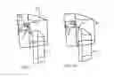
FIG. 1 shows a transparent view of two segments 1, the semi-circle 2, the square 32 and the clip 42.
FIG. 1A shows a transparent view of two segments 1, as recited in FIG. 1, and the semi-circle 2.
DETAILED DESCRIPTION
FIG. 1 shows a transparent view of two segments 1, in the expanded position, for which the semi-circle 2 is held by a loosely fastened attachment comprising a pin or rivet 42. The semi-circle hands is in the square 42 hollow space. The semi-circle is in the compressed position caused by pressure from the passing of a subsequent segment. During expansion the loosely fitted circle 2 in square 32 provides a mechanical means for the circle 2 to be pushed from the cavity and through the square 42 hollow space thus clearing the way for the subsequent segment 1 to pass.
FIG. 1A shows two segments 1, wherein the semi-circle is fastened in the weighted position; thus causing it to return to its original position thereby prohibiting reverse motion of subsequent segments 1. inner cavity, effectively creating a block which prohibits reverse motion of subsequent segments 1. An additional locking mechanism can provide permanence if desired; such as, but not limited to, a clip (not shown) for which to hold the semi-circle 2 in a particular position.
Claims
1. A semi-circle shaped key fitted in the hollow space cut out of a segment wall of a member beam from the parent application U.S. Ser. No. 15/703,993, used for gaining rigidity between the segments, wherein designed to prohibit reverse motion of segments joined together where movement of said segment is desired in one direction, but it is necessary to prohibit reverse motion in the opposite direction, comprising: a semi-circle, wherein said semi-circle is fastened loosely off center in a hollow square space in the walls of said segments;
wherein said semi-circle comprises;
a means for loosely fastening in the hollow space in a manner that allows for movement while receiving pressure from a passing segment,
further said semi-circle comprising:
an off center position fastening providing means for it to be weighted on one side, thereby returning to its original position of protruding into the cavity of the segment, and automatically prohibiting reverse motion of the subsequent segment.
Images & Drawings included:

Sources:
- United States Patent and Trademark Office - verify current appl. status at the USPTO↗
Recent applications in this class:
- » 20240117634 2024-04-11
Studs with triangular longitudinal channels - » 20230358044 2023-11-09
Anchorage device, anchorage comprising the anchorage device and method of producing the anchorage - » 20230088085 2023-03-23
Steel Thermal Stud - » 20220403654 2022-12-22
Structural post with internal connector system - » 20220120083 2022-04-21
Structural post with internal connector system - » 20220090381 2022-03-24
Modular framing structure design and a method of using the same - » 20200308834 2020-10-01
Strut and method of using same - » 20200270865 2020-08-27
Structural element - » 20200102750 2020-04-02
Self-leveling Detachable Base - » 20200102749 2020-04-02
Apparatus for supporting overhead structure