Wheel having image display
US20190291507A1
2019-09-26
16/220,308
2018-12-14
✅ Patent granted
US 10,710,400 B2
2020-07-14
-
-
Jason R Bellinger
Cooper Legal Group, LLC
2038-12-14
Abstract:
A hub for displaying images is provided. The hub includes a hub body and a dazzling imaging portion, in which the hub body includes a wheel disc surface, a center flange and a rim, the wheel disc surface includes spokes, one end of each spoke is connected to the center flange and the other end is connected to the rim, the center flange includes a center hole and bolt holes uniformly distributed around the center hole, and the rim is connected to the ends of the spokes and extends in a direction perpendicular to the wheel disc surface; the dazzling imaging portion is composed of a circuit board, connecting wires, an FPC, a battery, a decorative cap and decorative lights; and the decorative cap is composed of a circular cover plate and one or more strip claw arms.
Inventors:
- Weidong LIU 85 🇨🇳 Qinhuangdao, China
- Chuanqun LI 4 🇨🇳 Qinhuangdao, China
- Shaoqian WANG 16 🇨🇳 Qinhuangdao, China
- Congshan JIA 1 🇨🇳 Qinhuangdao, China
Assignee:
- CITIC DICASTAL CO., LTD 296 🇨🇳 Qinhuangdao, China
Applicant:
Interested in similar patents?
Get notified when new applications in this technology area are published.
Classification:
B60B7/006 » CPC main
Wheel cover discs, rings, or the like, for ornamenting, protecting or obscuring, wholly or in part, the wheel body, rim, hub, or tyre sidewall characterised by the surface the dominant aspect being the surface appearance the surface being reflective or including lighting
B60Q1/326 » CPC further
Arrangement of optical signalling or lighting devices, the mounting or supporting thereof or circuits therefor the devices being primarily intended to indicate the vehicle, or parts thereof, or to give signals, to other traffic for indicating vehicle sides, e.g. clearance lights on or for wheels
G09F21/045 » CPC further
Mobile visual advertising by land vehicles supported by the wheels
B60B7/00 IPC
Wheel cover discs, rings, or the like, for ornamenting, protecting or obscuring, wholly or in part, the wheel body, rim, hub, or tyre sidewall
B60Q1/32 IPC
Arrangement of optical signalling or lighting devices, the mounting or supporting thereof or circuits therefor the devices being primarily intended to indicate the vehicle, or parts thereof, or to give signals, to other traffic for indicating vehicle sides, e.g. clearance lights
G09F21/04 IPC
Mobile visual advertising by land vehicles
B60B1/042 » CPC main
Spoked wheels; Spokes thereof; Wheels with wire or other tension spokes; Attaching spokes to rim or hub Attaching spokes to hub
B60B27/0047 » CPC further
Hubs characterised by functional integration of other elements
B60B1/0261 » CPC further
Spoked wheels; Spokes thereof; Wheels with wire or other tension spokes characterised by spoke form
B60B1/04 IPC
Spoked wheels; Spokes thereof; Wheels with wire or other tension spokes Attaching spokes to rim or hub
B60B1/02 IPC
Spoked wheels; Spokes thereof Wheels with wire or other tension spokes
B60B27/00 IPC
Hubs
Description
CROSS-REFERENCE TO RELATED APPLICATIONS
The present application claims benefit of Chinese Patent Application No. 201810232961.3, filed on Mar. 21, 2018, the contents of which are hereby incorporated by reference in its entirety.
BACKGROUND
Automobiles have evolved into important products for people's daily lives. People are increasingly demanding automotive aesthetics while pursuing performance. As an important part of an automobile, the automobile hub is not only related to the driving safety and comfort of the automobile, but also has an important influence on the aesthetics of the entire vehicle. As an important safety part and appearance part of the automobile, the aluminum alloy hub plays an important role in good comprehensive performance of safety, aesthetics, recyclability and light weight (at least 30% of the weight reduced), especially wins the favor of the market in the attractive appearance, and has become the best choice for people.
However, as people's demands for the appearance and personalization of automobiles are increasing, it is hoped that the wheel disc surface of the wheel also has a better decorative and display function, thereby providing a better body appearance. At present, the wheel disc surface of the wheel is generally decorated by color or color register coating thereof. This method only can produce a static decorative effect on the wheel disc surface. Decorative lights are arranged on the wheel disc surfaces of some wheels at present to provide a dynamic wheel disc decoration effect. However, since the wheel is a non-stop rotating component, the decorative lights on the wheel are difficult in obtaining electric energy from the body. Generally, only a battery with small capacity can be used for supplying power, which limits the selection and use of the decorative lights.
SUMMARY
The present disclosure relates to the technical field of motor vehicle parts, specifically to a hub for displaying dynamic images.
The object of the present disclosure is to provide a dynamic imaging hub having an independent power supply system. Specifically, a hub with an automatic power generation system is provided. The use of the hub is expected to achieve different dynamic patterns on the front of the hub during driving of the automobile by controlling the parameters such as color and strength of a series of light-emitting diodes (LED) mounted on front ribs of the hub according to the rotational speed of the hub.
In one aspect of the present disclosure, provided is a hub for displaying images, the hub comprising a hub body and a dazzling imaging portion, the hub body includes a wheel disc surface, a center flange and a rim, the wheel disc surface includes spokes, one end of each spoke is connected to the center flange and the other end is connected to the rim, the center flange includes a center hole and bolt holes uniformly distributed around the center hole, and the rim is connected to the ends of the spokes and extends in a direction perpendicular to the wheel disc surface; the dazzling imaging portion is composed of a circuit board, connecting wires, an FPC, a battery, a decorative cap and decorative lights; the decorative cap is composed of a circular cover plate and one or more strip claw arms, the circular cover plate is configured to cover the center hole of the center flange, and the claw arms extend outward along the spokes; the decorative lights include LED light bars, and the LED light bars are configured such that the beads thereof are separately controlled to be turned on or off; the circuit board is configured to control the beads of the LED light bars to light or extinguish according to certain time sequence; and the decorative lights, the battery and the circuit board are connected with the FPC into an electrical circuit by the connecting wires.
In a preferred aspect of the disclosure, the FPC is mounted on one of the claw arms of the decorative cap, with one end connected to the circuit board, the LED light bars are mounted on the FPC orderly, and the decorative lights are mounted on the remaining claw arms of the decorative cap.
In a preferred aspect of the disclosure, the hub for displaying images further includes a magnetic power generation portion, and the magnetic power generation portion includes a bearing end cap, a rotating shaft, a first bearing, a second bearing, an eccentric weight, a strong magnet, a bearing end cap, a magnetic coil and a bushing, in which the bearing end cap and the bearing end cap respectively mount the first bearing and the second bearing on the circuit board and the bushing, the two ends of the rotating shaft are respectively connected with the first bearing and the second bearing, and the eccentric weight and the strong magnet are fixed in the middle of the rotating shaft; the magnetic coil is mounted on the bushing; and the magnetic coil is connected to the battery and the circuit board via the connecting wires.
In a preferred aspect of the disclosure, the shape of the eccentric weight is selected from the group consisting of a pear shape, an ellipse, a non-full cylinder or a rounded corner triangle.
In a further preferred aspect of the disclosure, a decorative cover is mounted on the decorative cap and encloses the magnetic power generation portion and the battery inside the decorative cap.
In a preferred aspect of the disclosure, the hub for displaying images further includes a rotational speed detecting portion, the rotational speed detecting portion includes a rotational speed sensor, and the rotational speed sensor is in data connection with the circuit board.
In a further preferred aspect of the disclosure, the rotational speed sensor is mounted on the decorative cap and connected to the FPC, and the rotational speed sensor is configured to transmit the detected rotational speed to the circuit board through the FPC.
In a further preferred aspect of the disclosure, the hub for displaying images further includes a control portion, the control portion includes a memory and a processor, the memory stores imaging data, and the processor is configured to read the current speed of the automobile from the rotational speed sensor of the rotational speed detecting portion and analyze same, and control the turn-on time, frequency, strength and color of the beads of the LED light bars; and the magnetic power generation part is electrically connected with the dazzling imaging portion by a wire.
In a further preferred aspect of the disclosure, the middle fastening portion of the decorative cap is an elastic tensioning mechanism.
In other aspects of the present disclosure, further disclosed is the following technical solution.
During normal driving of the automobile, the hub drives the circuit board, the battery bushing and the magnetic coil to rotate; since the eccentric weight is a non-full cylinder and the center of gravity is lower, the eccentric weight, the strong magnet and the rotating shaft do not rotate under the co-action of the bearing system and the eccentric weight, the magnetic coil continuously cuts the magnetic lines to generate current, and power is supplied to the LED lights through the connecting wires.
In a preferred aspect of the present disclosure, the magnetic power generation portion further includes a battery, and the battery is configured to supply power to the LED lights when the rotational speed of the automobile is low; the magnetic power generation portion supplies power to the LED lights during normal driving, and stores redundant power to the battery.
In a preferred aspect of the present disclosure, the magnetic power generation portion is connected to the dazzling imaging portion, the control portion and the rotational speed detecting portion, and the control portion is connected with the dazzling imaging portion via a flexible circuit board.
In a preferred aspect of the present disclosure, the control portion is a hand-held cell phone, and the hand-held cell phone is in data connection with the rotational speed detecting portion and the dazzling imaging portion via Bluetooth or a wireless network.
In a preferred aspect of the present disclosure, the flexible circuit board (FPC) has super-flexibility, can be changed in shape according to the front rib structure of the hub, and cooperates with the decorative cap of the selected wheel model to realize a dynamic imaging function of the hub with different front ribs; the FPC has high temperature resistance and can work normally within 100° C., which effectively eliminates the influence on the dynamic imaging function due to the heat generated during continuous high-speed driving of the automobile, and improves the stability of the dynamic imaging function.
During normal driving of the automobile, the hub drives the circuit board, the battery bushing and the magnetic coil to rotate; since the eccentric weight is a non-full cylinder, the center of gravity is lower, and the eccentric weight, the strong magnet and the rotating shaft do not rotate under the co-action of the bearing system and the eccentric weight, the magnetic coil continuously cuts the magnetic lines to generate current, and power is supplied to the LED lights through the connecting wires. The hub and a brake disc are mounted on a load-bearing axle of the automobile, and a brake drum can be frictionally engaged with the brake disc to brake the automobile. The battery is connected to the magnetic coil and the circuit board via connecting wires respectively. The battery supplies power to the LED lights when the rotational speed of the automobile is low; and the magnetic power generation portion supplies power to the LED lights during normal driving, and stores redundant power to the battery. The control system is mounted in the circuit board, the rotational speed sensor detects the rotational speed of the hub and transmits the detected data to the control system, and the control system controls the parameters such as color, strength and frequency of a series of LED lights mounted in the FPC via a pre-written program according to the rotational speed of the hub, so that the front of the hub presents different dynamic images.
The wheel of the present disclosure has the capability of dynamic imaging, and has the characteristics of simple structure, stable performance, safety and reliability.
BRIEF DESCRIPTION OF DRAWINGS
The embodiments of the present disclosure will be described in detail below in combination with the accompanying drawings, in which:
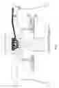
FIG. 1 is a structure diagram of a dynamic imaging hub according to the present disclosure.
FIG. 2 is a distribution diagram of a power generation mechanism in the dynamic imaging hub according to the present disclosure.
FIG. 3 is a schematic diagram of a front structure of the dynamic imaging hub according to the present disclosure.
FIG. 4 is a circuit principle diagram of the dynamic imaging hub according to the present disclosure.
LIST OF REFERENCE SYMBOLS
-
- 1—hub, 2—decorative cap, 3—circuit board, 4—first bearing end cap, 5—rotating shaft, 6—first bearing, 7—connecting wire, 8—FPC, 9—rotational speed sensor, 10—brake drum, 11—brake disc, 12—axle, 13—battery, 14—second bearing, 15—eccentric weight, 16—strong magnet, 17—second bearing end cap, 18—magnetic coil, 19—bushing, 20—decorative cover, 21—LED light, 22—decorative light; A—magnetic power generation portion, B—rotational speed detecting portion, C—dazzling imaging portion and D—control portion.
DETAILED DESCRIPTION
First Embodiment
In the present embodiment, provided is a hub for displaying dynamic images, the hub comprising a hub body and a dazzling imaging portion, in which the hub body includes a wheel disc surface, a center flange and a rim, the wheel disc surface includes spokes, one end of each spoke is connected to the center flange and the other end is connected to the rim, the center flange includes a center hole and bolt holes uniformly distributed around the center hole, and the rim is connected to the ends of the spokes and extends in a direction perpendicular to the wheel disc surface; the dazzling imaging portion is composed of a circuit board, connecting wires, an FPC, a battery, a decorative cap and decorative lights; the decorative cap is composed of a circular cover plate and one or more strip claw arms, the circular cover plate is configured to cover the center hole of the center flange, and the claw arms extend outward along the spokes; the decorative lights include LED light bars, and the LED light bars are configured such that the beads thereof are separately controlled to be turned on or off; the circuit board is configured to control the beads of the LED light bars to light or extinguish according to certain time sequence; and the decorative lights, the battery and the circuit board are connected with the FPC into an electrical circuit by the connecting wires. The FPC is mounted on one of the claw arms of the decorative cap, with one end connected to the circuit board, the LED light bars are mounted on the FPC orderly, and the decorative lights are mounted on the remaining claw arms of the decorative cap. The hub for displaying dynamic images further includes a magnetic power generation portion, and the magnetic power generation portion includes a bearing end cap, a rotating shaft, a first bearing, a second bearing, an eccentric weight, a strong magnet, a bearing end cap, a magnetic coil and a bushing, in which the bearing end cap and the bearing end cap respectively mount the first bearing and the second bearing on the circuit board and the bushing, the two ends of the rotating shaft are respectively connected with the first bearing and the second bearing, and the eccentric weight and the strong magnet are fixed in the middle of the rotating shaft; the magnetic coil is mounted on the bushing; and the magnetic coil is connected to the battery and the circuit board via the connecting wires. The shape of the eccentric weight is selected from the group consisting of a pear shape, an ellipse, a non-full cylinder or a rounded corner triangle. A decorative cover is mounted on the decorative cap and encloses the magnetic power generation portion and the battery inside the decorative cap. The hub for displaying dynamic images further includes a rotational speed detecting portion, the rotational speed detecting portion includes a rotational speed sensor, and the rotational speed sensor is in data connection with the circuit board. The rotational speed sensor is mounted on the decorative cap and connected to the FPC, and the rotational speed sensor is configured to transmit the detected rotational speed to the circuit board through the FPC. The hub for displaying dynamic images further includes a control portion which includes a memory and a processor. The memory stores imaging data, and the processor is configured to read the current speed of the automobile from the rotational speed sensor of the rotational speed detecting portion and analyze same, and control the turn-on time, frequency, strength and color of the beads of the LED light bars; and the magnetic power generation part is electrically connected with the dazzling imaging portion by a wire. The middle fastening portion of the decorative cap is an elastic tensioning mechanism.
During normal driving of the automobile, the hub drives the circuit board, the battery bushing and the magnetic coil to rotate; since the eccentric weight is a non-full cylinder, the center of gravity is lower, the eccentric weight, the strong magnet and the rotating shaft do not rotate under the co-action of the bearing system and the eccentric weight, the magnetic coil continuously cuts the magnetic lines to generate current, and power is supplied to the LED lights through the connecting wires. The hub and a brake disc are mounted on a load-bearing shaft of the automobile, and a brake drum can be frictionally engaged with the brake disc to brake the automobile. The battery is connected to the magnetic coil and the circuit board via connecting wires respectively. The battery supplies power to the LED lights when the rotational speed of the automobile is low; and the magnetic power generation portion supplies power to the LED lights during normal driving, and stores redundant power to the battery. The control system is mounted in the circuit board, the rotational speed sensor detects the rotational speed of the hub and transmits the detected data to the control system, and the control system controls the parameters such as color, strength and frequency of a series of LED lights mounted in the FPC via a pre-written program according to the rotational speed of the hub, so that the front of the hub presents different dynamic images. The principle of imaging is to calculate the change frequency of the LED lights by means of the rotational speed. It is supposed that the rotational speed of the hub is 60 rpm, that is, 60 revolutions per minute, and one revolution per second. A string of LED lights is arranged in the radial direction on the decorative cap of the hub. It is assumed to be 10 LED lights which are numbered from 1 to 10 from the axle center to the edge of the hub. Then it is assumed that the LED lights are 0 degrees just above the hub at 0 second; if the effect of 6:00 is desired to be displayed on the hub, No. 1-10 lights are lightened at 0 second to display the minute hand, No. 1-5 lights are lightened at 0.5 second to display the hour hand, then No. 1-10 lights are lightened at 1 second to display the minute hand, No. 1-5 lights are lightened at 1.5 second to display the hour hand, and so on. Thus, a complete 6:00 full-clock image will be displayed through visual persistence of human eyes. Complex patterns are also deduced by analogy, as long as 3 points are accurately calculated: 1, initial phase of the LED lights; 2, rotational speed of the hub 1; and 3, current time. It is possible to know the positions of the LED lights at certain moment. As long as the different LED lights are lightened at different positions, a complete pattern can be finally formed. As the number of the LED lights increases, the image effect is clearer.
Second Embodiment
The shape of the eccentric weight of the magnetic power generation portion can be selected from various structures, and three kinds are listed in the present disclosure and compared by experiments. The comparison method is to mount the eccentric weights of the three structures on a tester respectively, and detect the rotational speed of the wheel when the eccentric weights deflect 30 degrees. The test data and results are shown in Table 1.
| TABLE 1 |
| Comparison of wheel speeds for different eccentric |
| weights when the same weight deflects. |
| Eccentric weight model | Hub size | Bearing model | Wheel speed |
| A Pear shape | 20 inches | MR72ZZ | 25 r/s |
| B Ellipse | 20 inches | MR72ZZ | 8 r/s |
| C Rounded corner triangle | 20 inches | MR72ZZ | 15 r/s |
It can be seen from the above table that the pear-shaped structure in the A scheme is optimal.
Claims
1. A hub for displaying images, the hub comprising a hub body and a dazzling imaging portion, wherein the hub body comprises a wheel disc surface, a center flange and a rim, the wheel disc surface comprises spokes, one end of each spoke is connected to the center flange and the other end is connected to the rim, the center flange comprises a center hole and bolt holes uniformly distributed around the center hole, and the rim is connected to the ends of the spokes and extends in a direction perpendicular to the wheel disc surface; the dazzling imaging portion is composed of a circuit board, connecting wires, an flexible circuit board (FPC), a battery, a decorative cap and decorative lights; the decorative cap is composed of a circular cover plate and one or more strip claw arms, the circular cover plate is configured to cover the center hole of the center flange, and the claw arms extend outward along the spokes; the decorative lights comprise light-emitting diode (LED) light bars, and the LED light bars are configured such that the beads thereof are separately controlled to be turned on or off; the circuit board is configured to control the beads of the LED light bars to light or extinguish according to certain time sequence; and the decorative lights, the battery and the circuit board are connected with the FPC into an electrical circuit by the connecting wires.
2. The hub for displaying images according to claim 1, wherein the FPC is mounted on one of the claw arms of the decorative cap, with one end connected to the circuit board, the LED light bars are mounted on the FPC orderly, and the decorative lights are mounted on the remaining claw arms of the decorative cap.
3. The hub for displaying images according to claim 1, wherein the hub for displaying images further comprises a magnetic power generation portion, and the magnetic power generation portion comprises a bearing end cap, a rotating shaft, a first bearing, a second bearing, an eccentric weight, a strong magnet, a bearing end cap, a magnetic coil and a bushing, wherein the bearing end cap and the bearing end cap respectively mount the first bearing and the second bearing on the circuit board and the bushing, the two ends of the rotating shaft are respectively connected with the first bearing and the second bearing, and the eccentric weight and the strong magnet are fixed in the middle of the rotating shaft; the magnetic coil is mounted on the bushing; and the magnetic coil is connected to the battery and the circuit board via the connecting wires.
4. The hub for displaying images according to claim 1, wherein the shape of the eccentric weight is selected from the group consisting of a pear shape, an ellipse, a non-full cylinder or a rounded corner triangle.
5. The hub for displaying images according to claim 4, wherein a decorative cover is mounted on the decorative cap and encloses the magnetic power generation portion and the battery inside the decorative cap.
6. The hub for displaying images according to claim 1, wherein the hub for displaying images further comprises a rotational speed detecting portion, the rotational speed detecting portion comprises a rotational speed sensor, and the rotational speed sensor is in data connection with the circuit board.
7. The hub for displaying images according to claim 6, wherein the rotational speed sensor is mounted on the decorative cap and connected to the FPC, and the rotational speed sensor is configured to transmit the detected rotational speed to the circuit board through the FPC.
8. The hub for displaying images according to claim 1, wherein the hub for displaying images further comprises a control portion, the control portion comprises a memory and a processor, the memory stores imaging data, and the processor is configured to read the current speed of the automobile from the rotational speed sensor of the rotational speed detecting portion and analyze same, and control the turn-on time, frequency, strength and color of the beads of the LED light bars; and the magnetic power generation part is electrically connected with the dazzling imaging portion by a wire.
9. The hub for displaying images according to claim 1, wherein the middle fastening portion of the decorative cap is an elastic tensioning mechanism.
Images & Drawings included:


Sources:
- United States Patent and Trademark Office - verify current appl. status at the USPTO↗
Similar patent applications:
- » 20080101053
Multiplexed image displaying wheel assembly - » 10413489
Illumination optical unit employing dichroic mirror wheel and image display system including the illumination optical unit - » 20070137078
Displaying image mechanism wheel assembly - » 20200410912
Wheel dynamic imaging display rack - » 10829161
Manufacturing method of color wheel, and color wheel fabricated thereby and incorporated in color wheel assembly and image display apparatus - » 10851186
Manufacturing method of color wheel, and color wheel fabricated thereby and incorporated in color wheel assembly and image display apparatus - » 20230314920
PHOSPHOR WHEEL AND PROJECTION IMAGE DISPLAY DEVICE - » 20050030659
Color wheel, manufacturing method of same, and color wheel assembly and image display apparatus incorporating same - » 20240319738
System and Method for Displaying Animated Images from Wheeled Mobile Robots - » 20250189780
PHOSPHOR WHEEL, LIGHT SOURCE DEVICE, PROJECTION TYPE IMAGE DISPLAY DEVICE, AND METHOD FOR PRODUCING PHOSPHOR WHEEL
Recent applications in this class:
- » 20250050680 2025-02-13
Bicycle hub and spoke arrangement - » 20240308267 2024-09-19
Cycle Hub Assembly - » 20240066914 2024-02-29
WHEEL PLATE ASSEMBLY AND METHOD FOR PRODUCING WHEEL PLATE INCLUDING COMPOSITE MATERIAL - » 20190337327 2019-11-07
Spoke attachment flange for a hub for a bicycle wheel and method for mounting a spoke on the flange - » 20190337326 2019-11-07
Spoke attachment flange for a hub for a bicycle wheel, method for mounting a spoke on the flange and method for manufacturing the hub - » 20190329588 2019-10-31
Low-speed vehicle wheel assembly - » 20190291506 2019-09-26
Bicycle rear wheel hub - » 20190001745 2019-01-03
NON-PNEUMATIC WHEEL AND METHOD OF CONSTRUCTION - » 20190001744 2019-01-03
NON-PNEUMATIC WHEEL - » 20170313124 2017-11-02
SOLID CARBON REAR WHEEL COMPRISING A POLYGONALLY OUTSIDE CONTOURED HUB
Recent applications for this Assignee:
- » 20240116101 2024-04-11
Closed-loop control method and system for mold temperature in wheel casting process - » 20230381853 2023-11-30
Riser tube coating for cast aluminum alloy and using method thereof - » 20230194176 2023-06-22
Magnesium alloy material smelting device - » 20230194171 2023-06-22
Aluminum alloy material smelting device - » 20230193433 2023-06-22
Magnesium alloy, preparation method thereof, and process for preparing wheels by using the magnesium alloy - » 20230080640 2023-03-16
Spinning process of magnesium alloy wheel hub - » 20230074156 2023-03-09
Magnesium alloy for wheel and preparation method thereof - » 20230071499 2023-03-09
Forging process of magnesium alloy wheel hub - » 20230050493 2023-02-16
Casting ladle for casting aluminum alloy - » 20230003317 2023-01-05
Electric control valve detection device and electric control valve signal detection method