MOTOR CORE
US20190334414A1
2019-10-31
16/504,014
2019-07-05
Abstract:
A motor core has multiple silicon steel sheets and multiple layers of electrically insulating colloid. Each one of the multiple layers of electrically insulating colloid is disposed between adjacent two of the silicon steel sheets. This reduces the chance of forming eddy currents, reducing the eddy current loss of the motor core during operation.
Interested in similar patents?
Get notified when new applications in this technology area are published.
Classification:
C21D8/1244 » CPC further
Modifying the physical properties by deformation combined with, or followed by, heat treatment during manufacturing of articles with special electromagnetic properties the heat treatment(s) being of interest
C09D183/08 » CPC further
Coating compositions based on macromolecular compounds obtained by reactions forming in the main chain of the macromolecule a linkage containing silicon, with or without sulfur, nitrogen, oxygen, or carbon only; Coating compositions based on derivatives of such polymers; Polysiloxanes containing silicon bound to organic groups containing atoms other than carbon, hydrogen, and oxygen
H02K11/01 » CPC main
Structural association of dynamo-electric machines with electric components or with devices for shielding, monitoring or protection for shielding from electromagnetic fields, i.e. structural association with shields
C22C38/02 » CPC further
Ferrous alloys, e.g. steel alloys containing silicon
C21D8/12 IPC
Modifying the physical properties by deformation combined with, or followed by, heat treatment during manufacturing of articles with special electromagnetic properties
H02K1/27 IPC
Details of the magnetic circuit characterised by the shape, form or construction; Rotating parts of the magnetic circuit Rotor cores with permanent magnets
H02K1/04 » CPC further
Details of the magnetic circuit characterised by the material used for insulating the magnetic circuit or parts thereof
H02K15/03 » CPC further
Methods or apparatus specially adapted for manufacturing, assembling, maintaining or repairing of dynamo-electric machines of stator or rotor bodies having permanent magnets
H02K15/12 » CPC further
Methods or apparatus specially adapted for manufacturing, assembling, maintaining or repairing of dynamo-electric machines Impregnating, heating or drying of windings, stators, rotors or machines
H02K15/02 » CPC further
Methods or apparatus specially adapted for manufacturing, assembling, maintaining or repairing of dynamo-electric machines of stator or rotor bodies
Description
CROSS-REFERENCE TO RELATED APPLICATIONS
The present application is a divisional application of U.S. application Ser. No. 15/622,002 filed on Jun. 13, 2017, the disclosure of which is hereby incorporated by specific reference thereto.
BACKGROUND OF THE INVENTION
1. Field of the Invention
The present invention relates to a motor core, especially to a motor core capable of reducing eddy current loss of the motor core in operation.
2. Description of Related Art
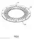
A motor includes a stator and a rotor, and the stator and the rotor together also can be called motor core. The stator is ring-shaped, and the rotor is cylindrical in shape. The stator and the rotor are made of a plurality of silicon steel sheets. Take the stator for example, as shown in FIGS. 8 to 10A, each one of the silicon steel sheets 90 is ring-shaped. Multiple positioning portions 91 are formed in a top surface of each one of the silicon steel sheets 90 at spaced intervals. Multiple silicon steel sheets 90 are stacked with each other and are engaged with each other by the positioning portions 91, such that the motor core has a thickness.
To form a motor core, multiple silicon steel sheets 90 are stacked with each other directly in the manufacturing process, and then combined with each other by welding or bonding, etc. Therefore, the magnetic line of force may pass through the multiple silicon steel sheets 90 during the operation of the motor, which means the magnetic line of force would run in the multiple silicon steel sheets 90. However, the motor core has a magnetic resistance that will slow down the magnetic field lines, that is, hysteresis phenomenon. Hysteresis phenomenon will cause loss of current, known as hysteresis loss. In addition, during the process of the magnetic line of force running in the motor core, turning and rotation of magnetic line will occur, which is the so-called phenomenon of eddy current. Eddy current phenomenon will cause loss of current, known as the eddy current loss. The silicon steel sheets 90 are directly stacked with each other, so the magnetic hysteresis loss and eddy current loss of the situation are particularly significant, and this will cause poor efficiency of the motor output.
To overcome the shortcomings of the conventional motor core, the present invention provides a motor core to mitigate or obviate the aforementioned problems.
SUMMARY OF THE INVENTION
The main objective of the present invention is to provide a motor core. The motor core has multiple silicon steel sheets and multiple layers of electrically insulating colloid. Each one of the multiple layers of electrically insulating colloid is disposed between adjacent two of the silicon steel sheets. This significantly reduces the chance of forming eddy currents, thereby drastically reducing the eddy current loss of the motor core during operation.
Other objects, advantages, and novel features of the invention will become more apparent from the following detailed description when taken in conjunction with the accompanying drawings.
BRIEF DESCRIPTION OF THE DRAWINGS
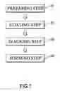
FIG. 1 is a block diagram of a method of manufacturing a motor core in accordance with the present invention;
FIG. 2 is a perspective view of a first embodiment of silicon steel sheets for a motor core made by the method in FIG. 1;
FIG. 3 is an exploded perspective view of the silicon steel sheets for the motor core made by the method in FIG. 1;
FIG. 4 is a cross sectional side view of the first embodiment of silicon steel sheets for a motor core made by the method in FIG. 1;
FIG. 4A is an enlarged side view of the silicon steel sheets in FIG. 4;
FIG. 5 is a perspective view of a first embodiment of the motor core made by the method in FIG. 1;
FIG. 6 is an exploded perspective view of a second embodiment of silicon steel sheets for a motor core made by the method in FIG. 1;
FIG. 7 is a cross sectional side view of the second embodiment of the silicon steel sheets for a motor core made by the method in FIG. 1;
FIG. 7A is an enlarged side view of the silicon steel sheets in FIG. 7;
FIG. 8 is a perspective view of conventional silicon steel sheets;
FIG. 9 is an exploded perspective view of the conventional silicon steel sheets in FIG. 8;
FIG. 10 is a cross sectional side view of the conventional silicon steel sheets in FIG. 8; and
FIG. 10A is an enlarged side view of the conventional silicon steel sheets in FIG. 10.
DETAILED DESCRIPTION OF PREFERRED EMBODIMENT
With reference to FIGS. 1 to 4A, a first embodiment of a manufacturing method of a motor core in accordance with the present invention comprises the following steps: a preparing step S1, a coating step S2, a stacking step S3, and a forming step S4.
In the preparing Step S1, multiple silicon steel sheets 10 are cleaned and dried.
In the coating step S2, an electrically insulating colloid 20 is coated between each pair of adjacent silicon steel sheets 10, and preferably, the electrically insulating colloid 20 is arranged annularly at spaced intervals on upper and lower surfaces of each pair of adjacent silicon steel sheets 10.
In the stacking step S3, the silicon steel sheets 10 on which the electrically insulating colloid 20 is applied are stacked on each other to form a layered structure in which a gap is formed between each pair of adjacent silicon steel sheets 10.
In the forming step S4, the stacked silicon steel sheets 10 are subjected to a colloid curing process so that the electrically insulating colloid 20 forms a thermosetting plastic, and the silicon steel sheets 10 are electrically unconnected and the finished product of a motor core is shown in FIG. 5. In addition, the colloid curing step may be a heating or anaerobic or pressurization process. The heating range of the colloid curing procedure is 100 C to 250 C when the colloid curing step is a heating step. For the pressurization program, the pressing force of the pressing process is 2000 kgf to 10000 kgf.
With reference to FIGS. 6 to 7A, a second embodiment of a manufacturing method for a motor core in accordance with the present invention is substantially the same as the first embodiment except for the following features. In the coating step S2, the electrically insulating colloid 20 is completely covered on the upper and lower surfaces of each pair of adjacent silicon steel sheets 10. In the stacking step S3, the gaps between the adjacent steel sheets 10 are filled with the electrically insulating colloid 20.
In summary, the main feature of the present invention is that the electrically insulating colloid 20 is applied on the upper and lower surfaces of each pair of adjacent silicon steel sheets 10 so that the electrically insulating colloid 20 is provided between the upper and lower surfaces of each pair of adjacent silicon steel sheets 10. The magnetic field lines cannot pass through the electrically insulating colloid 20 during the operation, so that the magnetic field lines can only run in the respective silicon steel sheets 10, and the chance of forming vortices is greatly reduced. Therefore, the present invention can significantly reduce the eddy current loss of the motor core during operation.
With reference to FIGS. 2 to 4A, a first embodiment of a motor core product in accordance with the present invention comprises multiple silicon steel sheets 10 and multiple layers of electrically insulating colloid 20.
Each one of the silicon steel sheets 10 is disk-shaped, and the electrically insulating colloids 20 are arranged at intervals on the upper and lower surfaces of each pair of adjacent silicon steel sheets 10, so that a gap is formed between each pair of adjacent silicon steel sheets 10.
With reference to FIGS. 6 to 7A, a second embodiment of a motor core in accordance with the present invention is substantially the same as the first embodiment except for the following features. The multiple layers of electrically insulating colloids 20 are completely coated on the upper and lower surfaces of each pair of adjacent silicon steel sheets 10 so that an electrically insulating colloid 20 is filled in the gap between each pair of adjacent silicon steel sheets 10.
Even though numerous characteristics and advantages of the present invention have been set forth in the foregoing description, together with details of the structure and function of the invention, the disclosure is illustrative only, and changes may be made in detail, especially in matters of shape, size, and arrangement of parts within the principles of the invention to the full extent indicated by the broad general meaning of the terms in which the appended claims are expressed.
Claims
What is claimed is:1. A motor core comprising:
multiple silicon steel sheets; and
multiple layers of electrically insulating colloid each disposed between adjacent two of the silicon steel sheets.
2. The motor core as claimed in claim 1, wherein each layer of the electrically insulating colloid is annularly arranged at spaced intervals on upper and lower faces of corresponding two of the silicon steel sheets, so that a gap is formed between the corresponding two of the silicon steel sheets.
Images & Drawings included:


Sources:
- United States Patent and Trademark Office - verify current appl. status at the USPTO↗
Similar patent applications:
- » 20250022639
NON-ORIENTED ELECTRICAL STEEL SHEET, IRON CORE AND MOTOR CORE, AND METHOD FOR MANUFACTURING IRON CORE AND MOTOR CORE - » 20200010918
Method for producing non-oriented electrical steel sheet, method for producing motor core, and motor core - » 20220278566
Method for producing non-oriented electrical steel sheet, method for producing motor core, and motor core - » 20190382867
Method for producing non-oriented electrical steel sheet, method for producing motor core, and motor core - » 20250149930
MOTOR CORE MANUFACTURING METHOD, POWER GENERATOR MANUFACTURING METHOD, MOTOR CORE, AND POWER GENERATOR - » 20230223827
MOTOR CORE ASSEMBLY AND MANUFACTURING METHOD FOR A MOTOR CORE ASSEMBLY - » 20240096531
NON-ORIENTED ELECTRICAL STEEL SHEET, MOTOR CORE, METHOD FOR MANUFACTURING NON-ORIENTED ELECTRICAL STEEL SHEET, AND METHOD FOR MANUFACTURING MOTOR CORE - » 20250140456
NON-ORIENTED ELECTRICAL STEEL SHEET, MOTOR CORE, METHOD FOR MANUFACTURING NON-ORIENTED ELECTRICAL STEEL SHEET, AND METHOD FOR MANUFACTURING MOTOR CORE - » 20060237096
Soft magnetic material, dust core, transformer core, motor core, and method for producing dust core - » 20230223798
MOTOR CORE AND MOTOR
Recent applications in this class:
- » 20240421668 2024-12-19
CRYOCOOLER - » 20200350805 2020-11-05
Magnetic shield for a superconducting generator - » 20200287445 2020-09-10
Termination unit - » 20200235642 2020-07-23
Motor rotor - » 20200112234 2020-04-09
Excitation operation brake - » 20190006917 2019-01-03
INTERFERENCE-SHIELDING HALL PLATE - » 20190006916 2019-01-03
Harmonic shunting electric motor with faceted shaft for improved torque transmission - » 20180358868 2018-12-13
Manufacturing method for a motor core - » 20180316246 2018-11-01
Electric machine having a rotor with retaining sleeve - » 20170104392 2017-04-13
ELECTRIC COMPRESSOR