Guide sleeve
US20190337180A1
2019-11-07
16/475,233
2018-01-16
✅ Patent granted
US 10,981,289 B2
2021-04-20
WO; PCT/EP2018/050923; 20180116
WO; WO2018/134167; 20180726
Lee D Wilson
Bookoff McAndrews, PLLC
2038-03-27
Abstract:
The invention relates to a guide sleeve for a machine tool for the automated placement of stripping claws, wherein a receiving slot (2) is provided at one end and a solid material base (4) is provided at the other end, and wherein a machine-tool stop (3) is positioned between the receiving slot (2) and the solid material base (4). The guide sleeve is characterised in that the receiving slot (2) is an elongate hole.
Assignee:
- BOXPLAN GMBH & CO.KG 3 🇩🇪 Radolfzell, Germany
- BOXPLAN GMBH & CO. KG 1 🇩🇪 Steisslingen, Germany
Applicant:
Interested in similar patents?
Get notified when new applications in this technology area are published.
Classification:
B26D7/1818 » CPC main
Details of apparatus for cutting, cutting-out, stamping-out, punching, perforating, or severing by means other than cutting; Means for removing cut-out material or waste by pushing out
B26D2007/189 » CPC further
Details of apparatus for cutting, cutting-out, stamping-out, punching, perforating, or severing by means other than cutting; Means for removing cut-out material or waste Mounting blanking, stripping and break-out tools
B26D2007/1809 » CPC further
Details of apparatus for cutting, cutting-out, stamping-out, punching, perforating, or severing by means other than cutting; Means for removing cut-out material or waste by stripping fingers
B23Q1/00 IPC
Members which are comprised in the general build-up of a form of machine, particularly relatively large fixed members
B26D7/18 IPC
Details of apparatus for cutting, cutting-out, stamping-out, punching, perforating, or severing by means other than cutting Means for removing cut-out material or waste
Description
TECHNICAL FIELD
The invention relates to a guide sleeve according to the preamble of claim 1.
BACKGROUND ART
The background art has no such guide sleeves, as the stripping claws according to the background art are hammered manually by personal into the stripping tool to be manufactured
OBJECT OF THE INVENTION
The object of the present invention is to overcome the disadvantages of the background art. In particular, a guide sleeve is to be provided that enables the automated manufacture of stripping tools, wherein not only the already mechanically or automatically used stripping pins are to be introduced to save time, but also the stripping claws, which have previously been introduced manually.
Solution of the Object
The features according to claim 1 lead to the solution of the object.
Advantageous embodiments are described in the dependent claims.
The guide sleeve has a receiving slot on one end and a solid material base on the other end, wherein a machine tool stop is arranged between the receiving slot and the solid material base. The receiving slot is thereby designed as an elongated slot. This has the advantage that received stripping claws can be held in a defined position in the guide sleeve before they can be driven mechanically into the stripping tool to be manufactured for example by a ram. Slipping of the stripping tool in the receiving slot prior to insertion into the stripping tool is successfully prevented.
The receiving slot comprises a stripping claw stop. This has the advantage that the received stripping claw is held in a defined position before it is mechanically inserted into the stripping tool by means of a ram. It is to be prevented that the stripping claw slips too deeply into the guide sleeve.
The receiving slot has a circumferential chamfer in a front outlet area of the guide sleeve. The circumferential chamfer is inclined at an angle of preferably 25 to 35° and more preferably at an angle of 30° with respect to a longitudinally proceeding central axis. It is advantageous here that the stripping claw is guided through the chamfer in a defined area of the receiving slot when loading the guide sleeve through the chamfer.
The receiving slot breaks through an outer wall of the guide sleeve at its longest extension. This is not mandatory. The longest extension describes the two points of an elongated hole that are farthest from each other. Another advantage here is that a broken through outer wall ensures the highest possible flexibility when loading the stripping claw.
A relief slot is present at right angles to the receiving slot. The relief slot and the receiving slot form a plus sign thereby. This arrangement ensures a defined flexibility of the overall arrangement. Furthermore, the outer wall of the guide sleeve breaks through.
The guide sleeve has an inner bore up to the solid material base. In the inner bore, for example, a ram can be provided, which serves for driving out the loaded stripping claw.
Between the machine tool stop and the solid material base, two through bores are present, wherein the two through bores are arranged orthogonally to one another in different planes. In addition, the solid material base has base slots arranged orthogonally to each other, wherein the first base slot extends up to the first through bore and the second base slot extends up to the second through bore. The two base slots have a base chamfer in an end outlet area.
DESCRIPTION OF THE FIGURES
Further advantages, features and details of the invention will become apparent from the following description of preferred exemplary embodiments and by means of the drawings; these show in:
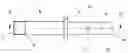
FIG. 1 a side view of a guide sleeve according to the invention;
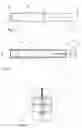
FIG. 2 a sectional view through the guide sleeve in FIG. 1 along the line II-II rotated by 90 degrees;
FIG. 3 a plan view of the guide sleeve in FIG. 1.
EXEMPLARY EMBODIMENT
In FIG. 1, a guide sleeve 1 for a machine tool for the automated setting of stripping claws not shown in detail is illustrated, wherein a receiving slot 2 is present on one end of the guide sleeve 1 and a solid material base 4 is present on the other end.
The receiving slot 2 is formed as an elongated slot and has a circumferential chamfer 6 in a front outlet area 7 of the guide sleeve 1. The circumferential chamfer is inclined at an angle of preferably 25 to 35° and more preferably at an angle of 30° with respect to a longitudinally proceeding central axis M. The receiving slot 2 respectively breaks through an outer wall 16 of the guide sleeve 1 at its longest extension.
A relief slot 8 is present at right angles to the receiving slot 2. The relief slot 8 also breaks through the outer wall 16 of the guide sleeve 1.
The receiving slot 2 comprises a stripping claw stop 5. It is to be prevented thereby that the stripping claw loaded in the guide sleeve slips too deeply into the guide sleeve.
A machine tool stop 3 is arranged between the receiving slot 2 and the solid material base 4.
The guide sleeve 1 has an inner bore 9 up to the solid material base 4. In the inner bore 9, for example, a ram can be provided, not shown in detail, which serves for driving out the loaded stripping claw.
Between the machine tool stop 3 and the solid material base 4, two through bores 10 and 11 are present, wherein the two through bores 10 and 11 are arranged orthogonally to one another in different planes.
The solid material base 4 also has orthogonally arranged base slots 12 and 13. The first base slot 12 extends up to the first through bore 10 and the second base slot 13 extends up to the second through bore 11. The two base slots 12 and 13 have a base chamfer 15 in an end outlet area 14. The base 15 preferably has an angle of 35 to 55° and more preferably an angle of 45° to the central axis M.
Although only a preferred embodiment of the invention has been described and illustrated, it will be apparent that a person skilled in the art can add numerous modifications without departing from the spirit and scope of the invention.
| LIST OF REFERENCE NUMERALS |
| 1 | Guide sleeve |
| 2 | Receiving slot |
| 3 | Machine tool stop |
| 4 | Solid material base |
| 5 | Stripping claw stop |
| 6 | Chamber |
| 7 | Front outlet area |
| 8 | Relief slot |
| 9 | Inner bore |
| 10 | Through bore |
| 11 | Through bore |
| 12 | Base slot |
| 13 | Base slot |
| 14 | End outlet area |
| 15 | Base chamfer |
| 16 | Outer wall |
| 17 | |
| 18 | |
| 19 | |
| 20 | |
| 21 | |
| 22 | |
| 23 | |
| 24 | |
| 25 | |
| 26 | |
| 27 | |
| 28 | |
| 29 | |
| 30 | |
| 31 | |
| 32 | |
| 33 | |
| 34 | |
| 35 | |
| 36 | |
| 37 | |
| 38 | |
| 39 | |
| 40 | |
| 41 | |
| 42 | |
| 43 | |
| 44 | |
| 45 | |
| 46 | |
| 47 | |
| 48 | |
| 49 | |
| 50 | |
| 51 | |
| 52 | M Central axis |
| 53 | |
| 54 | |
| 55 | |
| 56 | |
| 57 | |
| 58 | |
| 59 | |
| 60 | |
| 61 | |
| 62 | |
| 63 | |
| 64 | |
| 65 | |
| 66 | |
Claims
1. A guide sleeve for a machine tool for automated setting of stripping claws, wherein a receiving slot (2) is present on one end and a solid material base (4) on the other end and wherein a machine tool stop (3) is arranged between the receiving slot (2) and the solid material base (4),
characterized in that
the receiving slot (2) is an elongated hole.
2. The guide sleeve of claim 1, characterized in that the receiving slot (2) comprises a stripping claw stop (5).
3. The guide sleeve of claim 1, characterized in that the receiving slot (2) has a circumferential chamfer (6) in a front outlet area (7) of the guide sleeve (1).
4. The guide sleeve of claim 1, characterized in that the receiving slot (2) respectively breaks through an outer wall (16) of the guide sleeve (1) at its longest extension.
5. The guide sleeve of claim 1, characterized in that a relief slot (8) is present at right angles to the receiving slot (2).
6. The guide sleeve of claim 5, characterized in that the relief slot (8) breaks through the outer wall (16) of the guide sleeve (1).
7. The guide sleeve of claim 1, characterized in that the guide sleeve (1) has an inner bore (9) up to the solid material base (4).
8. The guide sleeve of claim 1, characterized in
that two through bores (10, 11) are present between the machine tool stop (3) and the solid material base (4), wherein the two through bores (10, 11) are arranged orthogonal to each other in different planes.
9. The guide sleeve of claim 1, characterized in that the solid material base (4) has base slots (12, 13) arranged orthogonally to each other.
10. The guide sleeve of claim 9, characterized in that the first base slot (12) extends up to the first through bore (10) and the second base slot (13) extends up to the second through bore (11).
11. The guide sleeve of claim 9, characterized in that the two base slots (12, 13) have a base chamfer (15) in an end outlet area (14).
Images & Drawings included:
Sources:
- United States Patent and Trademark Office - verify current appl. status at the USPTO↗
Similar patent applications:
- » 20180344480
Device for spinal surgery, corresponding guide sleeve and kit with guide sleeve - » 20230072036
GUIDE PIN, GUIDE SLEEVE, GUIDE, MAINTENANCE KIT, BRAKE CALIPER, ASSEMBLY METHOD - » 20210316707
Guide sleeve for guiding a collar of a relay valve for an electropneumatic modulator - » 16773686
Magnetic bit holder with automatic retracting guide sleeve - » 20050241381
Tire pressure gauge with guiding sleeve - » 20060081278
Umbrella operatively closed by directly pulling runner downwardly along a guiding sleeve - » 20070059192
Flanged sleeve guide - » 20060141417
Method for making surgical guiding sleeves components for a surgical template - » 20050201883
Scroll machine with stepped sleeve guide - » 13975385
Device, system and method for in-situ drill guide sleeve orientation
Recent applications in this class:
- » 20250282074 2025-09-11
FOOD PROCESSOR WITH DICING GRID ACCESSORY AND CLEANING TOOL THEREFOR - » 20250282073 2025-09-11
PUNCHING DEVICE AND PUNCHING METHOD USING SAME - » 20250282072 2025-09-11
PUNCH, PUNCHING MACHINE AND METHOD USING THE SAME - » 20250144835 2025-05-08
FOOD CUTTER - » 20250108532 2025-04-03
DEVICE, PROCESSING MACHINE, AND METHOD FOR SEPARATING BLANKS - » 20250001638 2025-01-02
SMART DIE OUTPUT LANE ASSEMBLY - » 20240173882 2024-05-30
ROTARY CUTTING SYSTEM, DIE BOARD AND SCRAP EJECTOR FOR SAME, AND METHODS OF ASSEMBLY - » 20240091970 2024-03-21
SHEET PROCESSING MACHINE - » 20240042643 2024-02-08
TOOL CLAMPING ASSEMBLY AND ASSEMBLY - » 20230191643 2023-06-22
Device and method for separating blanks
Recent applications for this Assignee:
- » 20190337182 2019-11-07
Device for inserting a first ram or a second ram in an alternating manner - » 20190337181 2019-11-07
STRIPPING CLAW