System and method for creation of a dynamically sharp filter
US20190339353A1
2019-11-07
16/035,586
2018-07-13
✅ Patent granted
US 10,742,333 B2
2020-08-11
-
-
Peter M Bythrow | Alexander L. Syrkin
Malone IP Law | Steven J. Malone
2038-07-13
Abstract:
A method of creating a dynamically sharp location based filter includes: placing a moving object containing two or more antennas used for direction finding of a radiation source within a anechoic testing chamber; moving one or more radio transmitters within the anechoic chamber relative to a future spatial location, angle, and/or position of the moving object over a defined time; record an expected angle of arrival of one or more signals of the one or more radio transmitters with respect to the future spatial location, angle, and/or position of the moving object over the defined time; and program a filter within the moving object based on the recorded expected angle of arrival of the one or more signals.
Applicant:
Interested in similar patents?
Get notified when new applications in this technology area are published.
Classification:
G01S1/302 » CPC further
Beacons or beacon systems transmitting signals having a characteristic or characteristics capable of being detected by non-directional receivers and defining directions, positions, or position lines fixed relatively to the beacon transmitters; Receivers co-operating therewith using radio waves; Systems for determining direction or position line using a comparison of transit time of synchronised signals transmitted from non-directional antennas or antenna systems spaced apart, i.e. path-difference systems the synchronised signals being continuous waves or intermittent trains of continuous waves, the intermittency not being for the purpose of determining direction or position line and the transit times being compared by measuring the phase difference Systems in which the direction is determined by using an interferometric type transmitting antenna array
H04B15/00 » CPC main
Suppression or limitation of noise or interference
G05D1/12 » CPC further
Control of position, course or altitude of land, water, air, or space vehicles, e.g. automatic pilot Target-seeking control
G06F21/602 » CPC further
Security arrangements for protecting computers, components thereof, programs or data against unauthorised activity; Protecting data Providing cryptographic facilities or services
H04B1/0071 » CPC further
Details of transmission systems, not covered by a single one of groups - ; Details of transmission systems not characterised by the medium used for transmission adapting radio receivers, transmitters andtransceivers for operation on two or more bands, i.e. frequency ranges with one or more circuit blocks in common for different bands using a common intermediate frequency for more than one band
H04B1/0475 » CPC further
Details of transmission systems, not covered by a single one of groups - ; Details of transmission systems not characterised by the medium used for transmission; Transmitters; Circuits with means for limiting noise, interference or distortion
H04B7/1858 » CPC further
Radio transmission systems, i.e. using radiation field; Relay systems; Active relay systems; Space-based or airborne stations; Stations for satellite systems; Satellite systems for providing broadband data service to individual earth stations Arrangements for data transmission on the physical system, i.e. for data bit transmission between network components
H04B7/18506 » CPC further
Radio transmission systems, i.e. using radiation field; Relay systems; Active relay systems; Space-based or airborne stations; Stations for satellite systems; Airborne stations Communications with or from aircraft, i.e. aeronautical mobile service
H04B7/18513 » CPC further
Radio transmission systems, i.e. using radiation field; Relay systems; Active relay systems; Space-based or airborne stations; Stations for satellite systems; Systems using a satellite or space-based relay Transmission in a satellite or space-based system
H04B7/18582 » CPC further
Radio transmission systems, i.e. using radiation field; Relay systems; Active relay systems; Space-based or airborne stations; Stations for satellite systems; Satellite systems for providing broadband data service to individual earth stations Arrangements for data linking, i.e. for data framing, for error recovery, for multiple access
H04B7/185 IPC
Radio transmission systems, i.e. using radiation field; Relay systems; Active relay systems Space-based or airborne stations; Stations for satellite systems
H04B1/10 IPC
Details of transmission systems, not covered by a single one of groups - ; Details of transmission systems not characterised by the medium used for transmission; Receivers Means associated with receiver for limiting or suppressing noise or interference
H04B1/00 IPC
Details of transmission systems, not covered by a single one of groups - ; Details of transmission systems not characterised by the medium used for transmission
H04B1/04 IPC
Details of transmission systems, not covered by a single one of groups - ; Details of transmission systems not characterised by the medium used for transmission; Transmitters Circuits
H04K3/00 IPC
Jamming of communication; Counter-measures
G01S1/30 IPC
Beacons or beacon systems transmitting signals having a characteristic or characteristics capable of being detected by non-directional receivers and defining directions, positions, or position lines fixed relatively to the beacon transmitters; Receivers co-operating therewith using radio waves; Systems for determining direction or position line using a comparison of transit time of synchronised signals transmitted from non-directional antennas or antenna systems spaced apart, i.e. path-difference systems the synchronised signals being continuous waves or intermittent trains of continuous waves, the intermittency not being for the purpose of determining direction or position line and the transit times being compared by measuring the phase difference
G06F21/60 IPC
Security arrangements for protecting computers, components thereof, programs or data against unauthorised activity Protecting data
G01S19/393 » CPC further
Satellite radio beacon positioning systems; Determining position, velocity or attitude using signals transmitted by such systems; Determining a navigation solution using signals transmitted by a satellite radio beacon positioning system the satellite radio beacon positioning system transmitting time-stamped messages, e.g. GPS [Global Positioning System], GLONASS [Global Orbiting Navigation Satellite System] or GALILEO Trajectory determination or predictive tracking, e.g. Kalman filtering
G01S5/0294 » CPC main
Position-fixing by co-ordinating two or more direction or position line determinations; Position-fixing by co-ordinating two or more distance determinations using radio waves Trajectory determination or predictive filtering, e.g. target tracking or Kalman filtering
G01S19/39 IPC
Satellite radio beacon positioning systems; Determining position, velocity or attitude using signals transmitted by such systems; Determining a navigation solution using signals transmitted by a satellite radio beacon positioning system the satellite radio beacon positioning system transmitting time-stamped messages, e.g. GPS [Global Positioning System], GLONASS [Global Orbiting Navigation Satellite System] or GALILEO
G01S5/02 IPC
Position-fixing by co-ordinating two or more direction or position line determinations; Position-fixing by co-ordinating two or more distance determinations using radio waves
H04B1/1081 » CPC further
Details of transmission systems, not covered by a single one of groups - ; Details of transmission systems not characterised by the medium used for transmission; Receivers; Means associated with receiver for limiting or suppressing noise or interference Reduction of multipath noise
H04B1/40 » CPC further
Details of transmission systems, not covered by a single one of groups - ; Details of transmission systems not characterised by the medium used for transmission; Transceivers, i.e. devices in which transmitter and receiver form a structural unit and in which at least one part is used for functions of transmitting and receiving Circuits
H04K3/44 » CPC further
Jamming of communication; Counter-measures; Jamming having variable characteristics characterized by the control of the jamming waveform or modulation type
Description
RELATED APPLICATIONS
This application claims priority to U.S. Provisional Application Ser. No. 62/531,881 titled “High Speed Data Sampling For Filtering, Recreating GPS Signals, and High Speed Communications” filed on Jul. 13, 2017 which is hereby incorporated by reference, in its entirety, for all it teaches and discloses.
FIELD OF THE INVENTION
The present invention discloses a system and method for digital direction finding and creation of a dynamically sharp filter.
SUMMARY
A method of creating a dynamically sharp location based filter includes: placing a moving object with at least a pair of antennas used for direction finding of a radiation source within a anechoic testing chamber; moving one or more radio transmitters within the anechoic chamber relative to a future spatial location, angle, and/or position of the moving object over a defined time; record an expected angle of arrival of one or more signals of the one or more radio transmitters with respect to the future spatial location, angle, and/or position of the moving object over the defined time; and program a filter within the moving object based on the recorded expected angle of arrival of the one or more signals.
A method for finding an orthogonal direction of a radiation source with respect a digitally optimized interference pattern of a first fixed electromagnetic element and a second fixed electromagnetic element includes: one or more processors including non-transitory memory programmed to: detect a first signal associated with the first fixed electromagnetic element, the first signal transmitted by the radiation source; detect a second signal associated with the second fixed electromagnetic element, the second signal transmitted by the radiation source; recursively digitally phase shift the first detected signal and/or the second detected signal to create a changing interference pattern; sample the changing interference pattern while digitally phase shifting the first detected signal and/or the second detected signal to obtain the digitally optimized interference pattern, wherein the digitally optimized interference pattern is formed by destructive interference between the first signal and the second signal to obtain a local minima associated with the destructive interference; bisect the digitally optimized interference pattern about the local minima forming a reference line or a reference plane; determine the orthogonal direction of the radiation source using the reference line or the reference plane; and use the determined orthogonal direction of the radiation source with respect to the digitally optimized interference pattern of the first fixed electromagnetic element and the second fixed electromagnetic element to at least partially control a vehicle, a flying device, an electronic device, a satellite, an autonomous vehicle, a projectile, an autonomous robot, a tracking system, or a combination thereof.
The method digitally optimized interference pattern may contain maximum near-field interference associated with the fixed positions of the first fixed electromagnetic element and the second fixed electromagnetic element. The fixed positions of the first fixed electromagnetic element and the second fixed electromagnetic element may be spaced apart less than 1 wavelength of the first signal or the second signal. The fixed positions of the first fixed electromagnetic element and the second fixed electromagnetic element may be spaced apart less than V2 wavelength of the first signal and/or the second signal. The fixed positions of the first fixed electromagnetic element and the second fixed electromagnetic element may be spaced apart approximately ¼ wavelength or ¼ wavelength multiples of the first signal and/or the second signal. The local minima of the digitally optimized interference pattern may be a maximized local minima of the destructive interference between the first signal and the second signal. The bisection of the digitally optimized interference pattern may be a symmetrical bisection about an axis formed by the local minima. The fixed positions of the first fixed electromagnetic element and the second fixed electromagnetic element may be intentionally spaced apart to cause destructive interference between the first signal and the second signal. The digitally optimized interference pattern may be a digitally optimized near-field interference pattern. The first fixed electromagnetic element and the second fixed electromagnetic element may be co-located on the same printed circuit board. The first fixed electromagnetic element and the second fixed electromagnetic element may be electrical elements of an integrated circuit chip package. The first fixed electromagnetic element and the second fixed electromagnetic element may be electrical antennas. The first fixed electromagnetic element and the second fixed electromagnetic element may be at least partially encapsulated in a common medium. The first fixed electromagnetic element and the second fixed electromagnetic element may be similar electrical antennas. The first fixed electromagnetic element and the second fixed electromagnetic element may be non-similar electrical antennas. The first fixed electromagnetic element or the second fixed electromagnetic element may be a ground plane of a printed circuit board. The first fixed electromagnetic element or the second fixed electromagnetic element may be a planar micro-strip antenna. The first fixed electromagnetic element and/or the second fixed electromagnetic element may be printed antennas. The first fixed electromagnetic element and the second fixed electromagnetic element may be separated by a dielectric layer of a printed circuit board. The radiation source may be a moving electromagnetic radiation source.
BRIEF DESCRIPTION OF THE DRAWINGS
In order that the advantages of the invention will be readily understood, a more particular description of the invention briefly described above will be rendered by reference to specific embodiments illustrated in the appended drawings. Understanding that these drawings depict only typical embodiments of the invention and are not therefore to be considered limiting of its scope, the invention will be described and explained with additional specificity and detail through use of the accompanying drawings, in which:
FIG. 1 shows a direction finding antenna system in accordance with an embodiment of the invention;
FIG. 2 shows a direction finding antenna method in accordance with an embodiment of the invention;
FIG. 3 shows a direction finding antenna method in accordance with an embodiment of the invention;
FIG. 4 show a direction finding antenna system in accordance with an embodiment of the invention; and
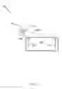
FIG. 5, shows a moving device (DUT, device under test) within an anechoic chamber.
DETAILED DESCRIPTION
It will be readily understood that the components of the present invention, as generally described and illustrated in the Figures herein, could be arranged and designed in a wide variety of different configurations. Thus, the following more detailed description of the embodiments of the invention, as represented in the Figures, is not intended to limit the scope of the invention, as claimed, but is merely representative of certain examples of presently contemplated embodiments in accordance with the invention. The presently described embodiments will be best understood by reference to the drawings.
FIG. 1 shows a direction finding system and method 100 including a radiation source 102, electromagnetic radiation 114, a first signal 104 and a first element 108, a second signal 106 and a second element 110, and a common circuit board 112. In one embodiment, antenna element 108 and antenna element 110 create an interference pattern relative to the positioning of each antenna when receiving a radiated signal 114 by way of signals 104 and 106. The method includes: detecting a first signal 104 associated with the first fixed electromagnetic element 108, the first signal transmitted by the radiation source 102; detect a second signal 106 associated with the second fixed electromagnetic element 110, the second signal transmitted by the radiation source 102; recursively digitally phase shift the first detected signal and/or the second detected signal to create a changing interference pattern using one or more processors; sampling the changing interference pattern while digitally phase shifting the first detected signal and/or the second detected signal to obtain the digitally optimized interference pattern, wherein the digitally optimized interference pattern is formed by destructive interference between the first signal and the second signal to obtain a local minima associated with the destructive interference; bisecting the digitally optimized interference pattern about the local minima farming a reference line or a reference plane; determining the orthogonal direction of the radiation source using the reference line or the reference plane; and using the determined orthogonal direction of the radiation source with respect to the digitally optimized interference pattern of the first fixed electromagnetic element and the second fixed electromagnetic element to at least partially control a vehicle, a flying device, an electronic device, a satellite, an autonomous vehicle, a projectile, an autonomous robot, a tracking system, or a combination thereof.
FIG. 2 illustrates a method 200 described in relation to FIG. 1. The method includes: detecting a first signal 204 associated with the first fixed electromagnetic element 208, the first signal transmitted by the radiation source 216; detect a second signal 206 associated with the second fixed electromagnetic element 210, the second signal transmitted by the radiation source 216; recursively digitally phase shift the first detected signal and/or the second detected signal to create a changing interference pattern 216 using one or more processors; sampling the changing interference pattern while digitally phase shifting the first detected signal and/or the second detected signal to obtain the digitally optimized interference pattern 224, wherein the digitally optimized interference pattern is formed by destructive interference between the first signal and the second signal to obtain a local minima 222 associated with the destructive interference; bisecting 218 the digitally optimized interference pattern about the local minima forming a reference line or a reference plane 218; determining the orthogonal direction 220 of the radiation source 216 using the reference line or the reference plane; and using the determined orthogonal direction of the radiation source with respect to the digitally optimized interference pattern of the first fixed electromagnetic element and the second fixed electromagnetic element to at least partially control a vehicle, a flying device, an electronic device, a satellite, an autonomous vehicle, a projectile, an autonomous robot, a tracking system, or a combination thereof.
FIG. 3, illustrates a method 300 of pin pointing a radiation source using a pair of antenna pairs (two of FIG. 1). The method includes: bisecting 312 a first digitally optimized interference pattern about the local minima 318 forming a reference line or a reference plane 312 and determining the orthogonal direction 310 of the radiation source 302 using the reference line or the reference plane of a first pair of antennas; and bisecting 314 the second digitally optimized interference pattern about the local minima 316 forming a reference line or a reference plane 312 and determining the orthogonal direction 308 of the radiation source 302 using the reference line or the reference plane of a second pair of antennas; and determining the radiation source 302 to be at the intersection 302 of the first and second orthogonal directions.
FIG. 4, shows a function block diagram of a system for detecting, sampling, and processing interference patterns of the direction finding invention. A dual antenna diplexer is used to receive the radiation energy at the first antenna and the second antenna. Fast sampling at 1.8 GHz or higher is needed to sample differences between the two antenna interference patterns. Data sampled is processed by a FPGA with parallel data processing techniques. DAC, ADC, LNA and PA are used to condition, filter and detect signals in accordance know digital signal processing techniques.
FIG. 5, shows a moving device (DUT, device under test) within an anechoic chamber. Electromagnetic ration sources are positioned to create dynamically moving radiation sources within the anechoic chamber. The DUT (moving device) is positioned on a moving table and can pitch, roll, yaw, and change direction while under test. In one embodiment, a missile is the moving device positioned on the moving table and GPS constellations are the radio transmitters that can move within the anechoic chamber. A flight plan may be loaded to control GPS transmitters to create a future scenario of a flight of the missile. The missile may have a future starting location and future flight plan that is loaded into a program controlling positions and locations of GPS transmitters and positions and angles of the missile. The missile may record using direction finding antennas, transmission angles and positions of GPS radio sources relative to the missiles position, angle, direction, pitch roll, etc. and dynamically form a spatially sharp dynamic filter that is dependent on a specific time, day, flight plan, speed, and direction of a missile flight allowing the missile to be programmed with a dynamically sharp filter for a future missile flight. This would allow the missile to reject spoofing signals that do not conform to specific sharp filter requirement preprogrammed into a filter within the missile. GPS radios may also represent fixed or moving radiation sources such as moving vehicle radio systems, ground antenna systems, and orbiting radio systems.
The systems and methods disclosed herein may be embodied in other specific forms without departing from their spirit or essential characteristics. The described embodiments are to be considered in all respects only as illustrative and not restrictive. The scope of the invention is, therefore, indicated by the appended claims rather than by the foregoing description. All changes which come within the meaning and range of equivalency of the claims are to be embraced within their scope.
Claims
1. A method of creating a dynamically sharp location based filter comprising:
placing a moving object containing two or more antennas used for direction finding of a radiation source within a anechoic testing chamber;
moving one or more radio transmitters within the anechoic chamber relative to a future spatial location, angle, and/or position of the moving object over a defined time;
record an expected angle of arrival of one or more signals of the one or more radio transmitters with respect to the future spatial location, angle, and/or position of the moving object over the defined time; and
program a filter within the moving object based on the recorded expected angle of arrival of the one or more signals.
Images & Drawings included:


Sources:
- United States Patent and Trademark Office - verify current appl. status at the USPTO↗
Recent applications in this class:
- » 20250291022 2025-09-18
PREVENTING ALTIMETER INTERFERENCE - » 20250237732 2025-07-24
SYSTEM AND METHOD FOR LOCALIZING DEVICES USING NETWORK SIGNATURES AND COVERAGE MAPS MEASURED BY ROBOTS - » 20250224481 2025-07-10
PROVIDING TRANSIT INFORMATION - » 20250224480 2025-07-10
GEODETIC FRAME KALMAN FILTER FOR TARGET GEOLOCATION AND TRACKING - » 20250189618 2025-06-12
MACHINE-LEARNING TRAINED LOCAL-AREA ID TRACKING FOR RADIO STATE CONTROL OF ASSET TRACKERS - » 20250020760 2025-01-16
ASSET TRACKER, METHOD OF TRACKING AN ASSET AND SECURITY SERVER FOR LOCATING THE ASSET - » 20240302486 2024-09-12
GENERAL AND ROBUST DISTRIBUTED LINEAR FILTERING AND PREDICTION WITH OPTIMAL GAIN - » 20240019532 2024-01-18
Event detection on far edge mobile devices using delayed positioning data - » 20230366975 2023-11-16
OBJECT TRACKING METHOD AND SYSTEM - » 20230341505 2023-10-26
METHODS AND APPARATUS FOR POSITIONING OF A MOVING UNMANNED AERIAL VEHICLE