Actuator having two motors and cooling fan module using the same
US20200021211A1
2020-01-16
16/508,502
2019-07-11
✅ Patent granted
US 10,944,343 B2
2021-03-09
-
-
Thai T Dinh
Millman IP Inc.
2039-07-11
Abstract:
An actuator for a cooling fan module includes a controller, a first motor and a second motor. The controller includes a controlling unit configured to receive control commands, and a motor driving unit electrically connected to the controlling unit and powered by a DC power supply. The first motor is electrically connected to the motor driving unit. The second motor is connected in parallel to the first motor. The first motor and the second motor are synchronously driven and controlled by the controller.
Inventors:
- Ruifeng QIN 22 🇨🇳 Hong Kong, China
- Tao QU 9 🇨🇳 Shenzhen, China
- Kwokkuen TSE 1 🇨🇳 Hong Kong, China
Assignee:
- JOHNSON ELECTRIC INTERNATIONAL AG 212 🇨🇭 Murten, Switzerland
Applicant:
Interested in similar patents?
Get notified when new applications in this technology area are published.
Classification:
H02P7/29 » CPC further
Arrangements for regulating or controlling the speed or torque of electric DC motors for regulating or controlling an individual dc dynamo-electric motor by varying field or armature current by master control with auxiliary power using discharge tubes or semiconductor devices using semiconductor devices controlling armature supply only using pulse modulation
F04D15/00 IPC
Control, e.g. regulation, of pumps, pumping installations or systems
F04D15/0088 » CPC further
Control, e.g. regulation, of pumps, pumping installations or systems Testing machines
H02P7/292 » CPC further
Arrangements for regulating or controlling the speed or torque of electric DC motors for regulating or controlling an individual dc dynamo-electric motor by varying field or armature current by master control with auxiliary power using discharge tubes or semiconductor devices using semiconductor devices controlling armature supply only using static converters, e.g. AC to DC
H02P5/68 » CPC main
Arrangements specially adapted for regulating or controlling the speed or torque of two or more electric motors controlling two or more dc dynamo-electric motors
F04D15/0066 » CPC further
Control, e.g. regulation, of pumps, pumping installations or systems by changing the speed, e.g. of the driving engine
Description
CROSS REFERENCE TO RELATED APPLICATIONS
This non-provisional patent application claims priority under 35 U.S.C. § 119(a) from Patent Application No. 201810748380.5 filed in The People's Republic of China on Jul. 11, 2018.
FIELD OF THE DISCLOSURE
This present disclosure relates to a cooling fan module for a motor vehicle. In particular, the present disclosure relates to a cooling fan module with two motors.
BACKGROUND OF THE DISCLOSURE
In recent years, demands for an actuator having two or more motors to drive two or more devices is increasing rapidly. For example, to provide broader cooling area, a cool fan module for a vehicle should be equipped with two or more motors. When multiple motors are used in an actuator, coordinated control of multiple motors is required to achieve coordinated operation. Traditionally, this kind of actuator is expensive since it includes two or more relays or PWM units to respectively control the two or more motors to enable each of the motor can to be controlled independently. Therefore, a low cost actuator including two or more motors is desired.
SUMMARY
Thus, there is a desire for an actuator and a corresponding cooling fan module to address the aforementioned problems.
According to one aspect, an actuator for a cooling fan module is provided. The actuator includes a controller, a first motor and a second motor. The controller includes a controlling unit configured to receive control commands, and a motor driving unit electrically connected to the controlling unit and powered by a DC power supply. The first motor is electrically connected to the motor driving unit. The second motor is connected in parallel to the first motor. The first motor and the second motor are synchronously driven and controlled by the controller.
According to another aspect, a cooling fan module is provided. The cooling fan module includes the actuator as above and two fans respectively driven by the first and the second motors.
BRIEF DESCRIPTION OF THE DRAWINGS
A preferred embodiment of the disclosure will now be described, by way of example only, with reference to figures of the accompanying drawings. In the figures, identical structures, elements or parts that appear in more than one figure are generally labeled with a same reference numeral in all the figures in which they appear. Dimensions of components and features shown in the figures are generally chosen for convenience and clarity of presentation and are not necessarily shown to scale. The figures are listed below.
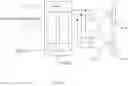
FIG. 1 is a schematic block diagram of a cooling fan module having two motors and an actuator in according with a first embodiment;
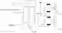
FIG. 2 is a schematic diagram of a circuit of the actuator of FIG. 1;
FIG. 3 is a schematic block diagram of a cooling fan module having two motors and an actuator in according with a second embodiment;
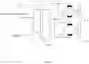
FIG. 4 is a schematic diagram of a circuit of the actuator of FIG. 3;
FIG. 5 is a schematic diagram of a circuit of the actuator in according with a third embodiment;
FIG.6 is a velocity sampling curve of the two motors of FIG. 1;
FIG.7 is a velocity sampling curve of the two motors of FIG. 3.
DETAILED DESCRIPTION OF THE PREFERRED EMBODIMENTS
The subject matter will be described in conjunction with the accompanying drawings and the preferred embodiments. The described embodiments are only a few and not all of the embodiments of the present disclosure. All other embodiments obtained by those ordinarily skilled in the art based on the embodiments of the present disclosure without any creative efforts fall within the protection scope of the present disclosure. It is to be understood that, the drawings are provided for reference only and are not intended to be limiting of the invention. The dimensions shown in the drawings are only for convenience of illustration and are not intended to be limiting.
It should be noted that when a component is considered to be “connected” to another component, it can be directly connected to another component or may also have a centered component. Unless otherwise defined, all technical and scientific terms used herein have the same meaning as commonly understood by those ordinarily skilled in the art. The terminology used in the specification of the present disclosure is only for the purpose of describing particular embodiments and is not intended to limit the invention.
Referring to FIG. 1, an embodiment of a cooling fan module includes an actuator in according with a first embodiment, a first cooling fan 5, and a second cooling fan 6. The actuator includes a controller 100 for brush DC motors, a motor 3 to drive the first cooling fan 5, and a motor 4 to drive the second cooling fan 6. The motor 3 and the motor 4 are both brush DC motor. The controller 100 includes a controlling unit 1 for receiving control commands (for example, PWM commands, LIN commands, etc.), and a motor driving unit 2 electrically connected to the controlling unit 1 and powered by a DC power supply. The motor drive unit 2 is provided with an output interface to simultaneously drive the motor 3 and the motor 4. The controller 100 is integrated in or on the motor 3. Therefore, the motor 3 is directly electrically coupled to the controller 100. The motor 4 is connected in parallel to the motor 3 with two additionally wires. Therefore, the motor 3 and the motor 4 share the same controller 100, and no additional controller is required.
Referring also to FIG. 2, in the first embodiment of actuator, the motor drive unit 2 includes a drive circuit for DC brush motor. Specifically, the motor drive unit 2 includes a PWM member 21, a DC voltage regulator 22, an electronic switch 23, a positive output terminal 24, and a negative output terminal 25. An output of the controlling unit 1 is connected to an input of the PWM member 21. The electronic switch 23 is connected between the negative output terminal 25 and a ground end of the DC power supply. An output of the PWM member 21 is connected to a switching end of the electronic switch 23. The DC voltage regulator 22 is connected between the positive output terminal 24 and the negative output terminal 25. The positive output terminal 24 is further connected to the positive output of the DC power supply. Preferably, the DC voltage regulator 22 can be a Zener diode. Preferably, the electronic switch 23 can be a triode or a field effect transistor.
In the first embodiment of actuator, the controlling unit 1 includes a plurality of analog-to-digital converters. Two of the analog-to-digital converters are respectively connected to the positive output terminal 24 and the negative output terminal 25 of the motor driving unit 2. Therefore, the controlling unit 1 can real-time monitor a voltage of the power supply voltage and a voltage applied to the motor 3.
In the first embodiment of actuator, the controller 100 further includes a current feedback unit. Preferably, the motor current feedback unit may comprise a resistor 8 and an amplifier 9 connected in parallel with the resistor 8. The resistor 8 is connected between the motor drive unit 2 and the ground end of the DC power supply. The output of the amplifier 9 is connected to the controlling unit 1. The voltage on the resistor 8 is amplified by the amplifier 9, and then applied to the micro-processing unit 1. Therefore, the current flowing through the motor can be derived with one of the analog-to-digital converters. The total current of the cooling fan module can be real-time monitored.
In the first embodiment of actuator embodiment, the controller 100 further includes an instruction input interface 7 for a PWM or LIN protocol, and the instruction input interface 7 is connected to a command receiving end of the controlling unit 1.
In the first embodiment of actuator embodiment, the cooling fan module further includes a failure diagnostic unit 10. The failure diagnostic unit 10 may include an electronic switch connected between the instruction input interface 7 and the ground end of the DC power supply. A switching end of the electronic switch 23 is connected to the controlling unit 1. When there is a failure for a current or voltage of the cooling fan module, such as current stall, overcurrent, overvoltage, undervoltage, etc., the diagnostic unit 10 can be turned off and set the cooling fan module to a protection mode.
Referring to FIG. 3, another embodiment of a cooling fan module includes an actuator in according with a second embodiment, the first fan 5, and the second fan 6. The actuator includes a controller 100′ for brushless motors, a motor 3′, and a motor 4′. The motor 3′ and the motor 4′ are both brushless DC motor. The controller 100′ includes a controlling unit 1′ for receiving control commands (for example, PWM commands, LIN commands, etc.), and a motor driving unit 2′ electrically connected to the controlling unit 1′ and powered by a DC power supply. The controller 100′ is integrated in or on the motor 3. Therefore, the motor 3′ is directly electrically coupled to the controller 100′. The motor 4′ is connected in parallel to the motor 3′ with three wires respectively connected to three phases of the motor 3′. Therefore, the motor 3′ and the motor 4′ share the same controller 100′, and no additional controller is required.
Referring to FIG. 4, in the second embodiment of the actuator, the motor drive unit 2′ includes a drive circuit for brushless DC motor. Specifically, the motor drive unit 2′ includes a three-phase bridge circuit 26 formed by six electric switches. The switching ends of the electric switches of the three-phase bridge circuit 26 are connected to the controlling unit 1′ and controlled by PWM signals generated by the controlling unit.
In the second embodiment of actuator, the controller 100′ further includes the instruction input interface 7 and/or the failure diagnostic unit 10 as that in the first embodiment of actuator.
Referring to FIG. 5, a third embodiment of the actuator includes the controller 100′ as the same in the second embodiment of actuator, the motor 3″, and the motor 4″. The motor 3″ is a brushless DC motor. The motor 4″ is a brush DC motor. The motor 3″ is directly coupled to the controller 100′. The motor 4′ is connected to the motor 3′ with two wires. One of the wires is connected to a positive input of the three-phase bridge circuit 26. The other wire is connected to any of three output of the three-phase bridge circuit 26.
In any of present embodiments above, the first fan 5 and the second fan 6 can work with synchronous speed control to be conveniently applied to certain field, such as cooling for an engine of automobile. Referring to FIG. 6, in the cooling fan with an actuator in according with the first embodiment and two brush DC motors, the speed of the two motors are different at a certain duty ratio of the electronic switch 23 according a controlling signal of controller 1. However, speed rates of the two motor relative to the duty ratio are almost the same. Therefore, the speed of the two motor are controlled synchronously by adjust the duty ratio of the PWM member 21. Referring to FIG. 7, in the cooling fan with an actuator in according with the second embodiment and two brushless DC motors, the speed of the two motors are almost the same at any duty ratio of the switches of the three-phase bridge circuit 26 according to a controlling signal of controller 1′.
The above descriptions are only preferred embodiments of the present disclosure, and are not to limit the present disclosure. Any changes, equivalents, modifications and the like, which are made within the spirit and principle of the present disclosure, shall fall within the protection scope of the present disclosure.
Claims
1. An actuator, comprising
a controller comprising a controlling unit configured to receive control commands, and a motor driving unit electrically connected to the controlling unit and powered by a DC power supply;
a first motor electrically connected to the motor driving unit; and
a second motor connected in parallel to the first motor, wherein the first motor and the second motor are synchronously driven and controlled by the controller.
2. The actuator of claim 1, wherein the controller is integrated in or on the first motor, the second motor is connected in parallel to the first motor with wires.
3. The actuator of claim 2, wherein the motor driving unit is configured to drive brush DC motors, and comprises a PWM member, a DC voltage regulator, an electronic switch, a positive terminal, and a negative output terminal, an output of the controlling unit is connected to an input of the PWM member, the electronic switch is connected between the negative output terminal and a ground end of the DC power supply, an output of the PWM member is connected to a switching end of the electronic switch, two coupling ends of the DC voltage regulator are respectively connected with the positive output terminal and the negative output terminal, the DC voltage regulator is connected between the positive output terminal and the negative output terminal, the positive output terminal is further connected to the positive output of the DC power supply.
4. The actuator of claim 3, wherein the controlling unit comprises a plurality of analog-to-digital converters, two of the analog-to-digital converters are respectively connected to the positive output terminal and the negative output terminal of the motor drive unit.
5. The actuator of claim 2, wherein the motor driving unit is configured to drive brushless DC motors, and comprises a three-phase bridge circuit formed by six electric switches, the switching ends of the electric switches of the three-phase bridge circuit are connected to the controlling unit and controlled by PWM signals generated by the controlling unit.
6. The actuator of claim 1, wherein the controller further comprises a current feedback unit comprising a resistor and an amplifier connected in parallel with the resistor, the resistor is connected between the motor drive unit and the ground end of the DC power supply, the output of the amplifier is connected to the controlling unit.
7. The actuator of claim 1, wherein the controller further comprises an instruction input interface for a PWM or LIN protocol, and the instruction input interface is connected to a command receiving end of the controlling unit.
8. The actuator of claim 7, further comprising a failure diagnostic unit, wherein the failure diagnostic unit comprises an electronic switch connected between the instruction input interface and the ground end of the DC power supply, a switching end of the electronic switch of the failure diagnostic unit is connected to the controlling unit.
9. The actuator of claim 3, wherein the first motor is a brush DC motor, the second motor is a brush DC motor.
10. The actuator of claim 5, wherein the first motor is a brushless DC motor, the second motor is a brush DC motor or a brushless DC motor.
11. A cooling fan module comprising the actuator of claim 1, and two fans respectively driven by the first motor and the second motor.
Images & Drawings included:


Sources:
- United States Patent and Trademark Office - verify current appl. status at the USPTO↗
Recent applications in this class:
- » 20250247027 2025-07-31
TORQUE CONTROLLER, TORQUE CONTROL METHOD, AND DRIVER - » 20250247026 2025-07-31
PREDICTIVE VOLTAGE BOOST FOR ACTIVE ELECTRIC MOTOR DAMPING - » 20250211142 2025-06-26
PAIRING FEATURE FOR DRIVING DC MOTORS WITH PARALLEL CAPACITORS IN OVERCURRENT RECOVERY MODE - » 20250055391 2025-02-13
CONTROL UNIT, DRIVE DEVICE, AND CONTROL METHOD - » 20250007430 2025-01-02
MOTOR CONTROL DEVICE - » 20240178770 2024-05-30
Head-mounted display apparatus and method for controlling the head-mounted display apparatus - » 20230231498 2023-07-20
Motor control device - » 20230163703 2023-05-25
Electrical drive system for a work machine having two electric motors that can be regulated independently of one another - » 20220376637 2022-11-24
Drive device, short circuit detection method, and computer program - » 20220103097 2022-03-31
SWING CAR CONTROLLER
Recent applications for this Assignee:
- » 20240344620 2024-10-17
THERMAL MANAGEMENT SYSTEM AND VALVE THEREOF - » 20240229945 2024-07-11
MULTI-PORT VALVE AND THERMAL MANAGEMENT SYSTEM HAVING MULTI-PORT VALVE - » 20240035581 2024-02-01
Multi-port valve, and thermal management system provided with same and application thereof - » 20230358325 2023-11-09
Multi-ports valve and thermal management system having same - » 20230268800 2023-08-24
ROTOR BEARING ARRANGEMENT FOR ELECTRIC MOTOR - » 20230043226 2023-02-09
Electric tool, electric motor and rotor assembly thereof - » 20230031766 2023-02-02
ELECTRIC POWER TOOL, MOTOR, AND ROTOR THEREOF - » 20220320921 2022-10-06
PUMP AND ELECTRIC MOTOR STATOR THEREOF - » 20220205516 2022-06-30
Gearbox and driving device using the same - » 20220205455 2022-06-30
Liquid pump