PERSONAL FAN DEVICE
US20200032815A1
2020-01-30
16/516,724
2019-07-19
Abstract:
An illustrated view of an exemplary personal fan device for directing fan wind to a desired location is presented. The personal fan device is useful for providing for providing a directed fanning of wind to a desired location. The personal fan device further provides a comfortable and efficient cooling or drying of a desired area for those having had surgery, injury, childbirth, etc. and have a need for healing of a wound in a sensitive area. The device has a cylinder that has a cover with preferably seven (7) holes and is void in an interior of the cylinder. The cylinder further is covered by a padding for comfort of an individual. A fan is presented that has a fan blade and a motor that is actuated by an actuator. The fan can be placed at a bottom of the cylinder for fan wind to enter the interior of the cylinder and exit through the holes in the cover.
Interested in similar patents?
Get notified when new applications in this technology area are published.
Classification:
F04D29/522 » CPC main
Details, component parts, or accessories; Casings; Connections of working fluid for axial pumps especially adapted for elastic fluid pumps
F04D25/06 » CPC further
Pumping installations or systems; Units comprising pumps and their driving means the pump being electrically driven
F04D19/002 » CPC further
Axial-flow pumps Axial flow fans
F04D29/52 IPC
Details, component parts, or accessories; Casings; Connections of working fluid for axial pumps
F04D19/00 IPC
Axial-flow pumps
Description
PRIORITY
This utility application claims the benefit of U.S. Provisional Patent Application No. 62/686,517, filed on Jul. 30, 2018, the entirety of which is hereby incorporated by reference.
FIELD OF THE INVENTION
This invention relates to fans. More particularly, it relates to a device to direct fan wind while being comfortable.
BACKGROUND
A fan is a powered machine used to create flow within a fluid, typically a gas such as air. A fan consists of a rotating arrangement of vanes or blades which act on the air. The rotating assembly of blades and hub is known as an impeller, a rotor, or a runner. Usually, it is contained within some form of housing or case. This may direct the airflow or increase safety by preventing objects from contacting the fan blades. Most fans are powered by electric motors, but other sources of power may be used, including hydraulic motors, hand cranks, internal combustion engines, and solar power.
Mechanically, a fan can be any revolving vane or vanes used for producing currents of air. Fans produce air flows with high volume and low pressure (although higher than ambient pressure), as opposed to compressors which produce high pressures at a comparatively low volume. A fan blade will often rotate when exposed to an air fluid stream, and devices that take advantage of this, such as anemometers and wind turbines, often have designs similar to that of a fan.
Typical applications include climate control and personal thermal comfort (e.g., an electric table or floor fan), vehicle engine cooling systems (e.g., in front of a radiator), machinery cooling systems (e.g., inside computers and audio power amplifiers), ventilation, fume extraction, winnowing (e.g., separating chaff of cereal grains), removing dust(e.g. sucking as in a vacuum cleaner), drying (usually in combination with a heat source) and to provide draft for a fire.
While fans are often used to cool people, they do not actually cool air (electric fans may warm it slightly due to the warming of their motors), but work by evaporative cooling of sweat and increased heat convection into the surrounding air due to the airflow from the fans. Thus, fans may become ineffective at cooling the body if the surrounding air is near body temperature and contains high humidity. During periods of very high heat and humidity, governments actually advise against use of fans.
Fans are difficult to hold in a desired position when held for long periods of time. When surgery or injury has occurred to sensitive areas, often ice packs are insufficient or dangerous to have on those sensitive areas. A fan can be used but is often causing discomfort and thus being unused during these times.
In light of the foregoing, there is a need to have a device that can provide cooling from a fan such that a fan can be in a comfortable position without the use of one's hands.
BRIEF DESCRIPTION OF THE DRAWINGS
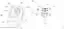
FIG. 1 is an illustrated view of an exemplary personal fan device.
DETAILED DESCRIPTION
The phrases “in one embodiment,” “in various embodiments,” “in some embodiments,” and the like are used repeatedly. Such phrases do not necessarily refer to the same embodiment. The terms “comprising,” “having,” and “including” are synonymous, unless the context dictates otherwise. Such terms do not generally signify a closed list.
“Above,” “adhesive,” “affixing,” “any,” “around,” “both,” “bottom,” “by,” “comprising,” “consistent,” “customized,” “enclosing,” “friction,” “in,” “labeled,” “lower,” “magnetic,” “marked,” “new,” “nominal,” “not,” “of,” “other,” “outside,” “outwardly,” “particular,” “permanently,” “preventing,” “raised,” “respectively,” “reversibly,” “round,” “square,” “substantial,” “supporting,” “surrounded,” “surrounding,” “threaded,” “to,” “top,” “using,” “wherein,” “with,” or other such descriptors herein are used in their normal yes-or-no sense, not as terms of degree, unless context dictates otherwise.
Reference is now made in detail to the description of the embodiments as illustrated in the drawings. While embodiments are described in connection with the drawings and related descriptions, there is no intent to limit the scope to the embodiments disclosed herein. On the contrary, the intent is to cover all alternatives, modifications and equivalents. In alternate embodiments, additional devices, or combinations of illustrated devices, may be added to, or combined, without limiting the scope to the embodiments disclosed herein.
Referring to FIG. 1, an illustrated view of an exemplary personal fan device 100 for directing fan wind to a desired location is presented. The personal fan device 100 is useful for providing for providing a directed fanning of wind to a desired location. The personal fan device 100 further provides a comfortable and efficient cooling or drying of a desired area for those having had surgery, injury, childbirth, etc. and have a need for healing of a wound in a sensitive area.
The personal fan device 100 has a cylinder 200 and a fan 300. The cylinder 200 is preferably a length of twenty-six (26) inches, however other lengths are hereby contemplated, including, but not limited to, twenty-four (24) inches, thirty (30) inches, etc. The cylinder 200 preferably has a diameter of fourteen (14) inches, however other diameters are hereby contemplated, including, but not limited to, ten (10) inches, eighteen (18) inches, etc. The cylinder 200 is preferably a cylindrical shape, however other shapes are hereby contemplated, including but not limited to, square, rectangular, round, etc.
The cylinder 200 has an outside 201, an inside 202, a back 203 and a plurality of covers 204. The cylinder 200 is preferably made of a plastic material, however other materials are hereby contemplated, including, but not limited to, poly-vinyl chloride (PVC), aluminum, etc.
The back 203 of the cylinder 200 is preferably open, thus allowing access to the inside area 202 of the cylinder 200. A first of the covers 204 of the cylinder 200 is removably coupled to a front end 205 of the cylinder 200. A second of the covers 204 of the cylinder 200 is removably coupled to the back 203 of the cylinder 200.
The covers 204 of the cylinder 200 are preferably one-eighth (⅛) inch in width, however other widths are here by contemplated, including, but not limited to, one-sixteenth inch ( 1/16), one-fourth (¼) inch, etc. The covers 204 are made of a plastic material, however other materials are hereby contemplated, including, but not limited to, poly-vinyl chloride (PVC), aluminum, etc.
The covers 204 of the cylinder 200 has a plurality of openings 206. The number of openings 206 is preferably seven (7), however other number of openings are hereby contemplated, including, but not limited to, five (5), nine (9), etc. The openings 206 of the covers 204 of the cylinder 200 preferably have a diameter of one (1) inch, however other diameters are hereby contemplated, including, but not limited to, one-half (0.5) inch, two (2) inches, etc. The covers 204 of the cylinder 200 preferably has a diameter of fourteen (14) inches, however other diameters are hereby contemplated, including, but not limited to, ten (10) inches, eighteen (18) inches, etc. The diameter of the covers 204 of the cylinder 200 is preferably the same diameter as the cylinder 200 but may be smaller or larger based on desired diameter.
An exterior 206 of the cylinder 200 preferably has a padding 207. The padding 207 is preferably foam, however other types of padding are hereby contemplated, including, but not limited to, cotton, down feathering, etc. The padding 207 is useful for comfort and longer using of the personal fan device 100.
The fan 300 has a body 301, a fan blade 302, a motor 303, a power source 304, an interior 305, an exterior 306 and an actuator 307. The fan 300 is preferably a personal fan but may be any other type of small fan. The fan 300 preferably has a diameter of eight (8) inches, however other diameters are hereby contemplated, including, but not limited to, six (6) inches, ten (10) inches, etc. The diameter of the fan 300 must be less than the diameter of the cylinder 200.
The fan 300 is coupled to the exterior 206 of the cylinder 200 between the front end 205 and the back 203 and further between, but not covered by, the padding 207.
The actuator 307 is coupled to the motor 303 which allows current from the power source 304 to flow to the motor 303 or to prevent current from flowing from the power source 304 to the motor 303. The actuator 307 is preferably a button, however other types of actuators are hereby contemplated, including, but not limited to, slide actuators, toggle switch, etc. The power source 304 is preferably ac/dc, but other power sources are hereby contemplated, including, but not limited to, rechargeable battery, disposable battery, solar, etc. The motor 303 and the power source 304 are configured to be contained in the interior 305 of the body 301 of the fan 300.
The fan blade 302 is controlled by the motor 303 and is coupled to the motor 303. When the motor 303 is actuated by the actuator 307, the fan blade 302 is rotated thus creating wind. The body 300 of the fan 300 may be inserted into the back 203 of the cylinder 200 and rests in the inside 202 of the cylinder 200. Optionally and or additionally, the body 301 of the fan 300 may have a padding 308. The padding 308 is preferably a foam material, however other materials are further contemplated, including, but not limited to, cotton, down, etc.
In the numbered clauses below, specific combinations of aspects and embodiments are articulated in a shorthand form such that (1) according to respective embodiments, for each instance in which a “component” or other such identifiers appear to be introduced (with “a” or “an,” e.g.) more than once in a given chain of clauses, such designations may either identify the same entity or distinct entities; and (2) what might be called “dependent” clauses below may or may not incorporate, in respective embodiments, the features of “independent” clauses to which they refer or other features described above.
Those skilled in the art will appreciate that the foregoing specific exemplary processes and/or devices and/or technologies are representative of more general processes and/or devices and/or technologies taught elsewhere herein, such as in the claims filed herewith and/or elsewhere in the present application.
The features described with respect to one embodiment may be applied to other embodiments or combined with or interchanged with the features of other embodiments, as appropriate, without departing from the scope of the present invention.
Other embodiments of the invention will be apparent to those skilled in the art from consideration of the specification and practice of the invention disclosed herein. It is intended that the specification and examples be considered as exemplary only, with a true scope and spirit of the invention being indicated by the following claims.
Claims
What is claimed is:1. A personal fan device for directing fan wind, the device comprising:
a cylinder, the cylinder comprising:
a back and front edge;
a cover, the cover being configured to allow air to egress from an interior of the cylinder, wherein the cover being coupled to front edge;
a plurality of openings, the plurality of openings being on the cover,
wherein the air passing through the plurality of openings; and
an exterior, the exterior having a padding;
fan, the fan comprising:
a body, the body having an exterior and an interior;
a fan blade, the fan blade for producing wind;
a motor, the motor being coupled in the interior of the body, wherein the motor being coupled to a power source, and wherein the motor being coupled to the fan blade;
an actuator, the actuator coupled to the exterior of the body, wherein the actuator configured to activate/deactivate the motor; and
wherein the fan being configured on the body of the cylinder.
2. The device of claim 1, wherein cylinder having a length being twenty-six (26) inches.
3. The device of claim 1, wherein the cylinder being made of a plastic material.
4. The device of claim 1, wherein the holes having a diameter being one (1) inch.
5. The device of claim 1, wherein the cylinder having a diameter being fourteen (14) inches.
6. The device of claim 1, wherein the plurality of holes being seven (7).
7. The device of claim 1, wherein the padding of the outside of the cylinder being foam.
8. The device of claim 1, wherein the padding of the body of the fan being foam.
9. The device of claim 1, wherein the fan having a diameter being eight (8) inches.
10. The device of claim 1, wherein the cover having a diameter being fourteen (14) inches.
11. The device of claim 1, wherein the actuator being a button.
12. The device of claim 1, wherein the power source being ac/dc.
13. The device of claim 1, wherein the diameter of the cylinder being the same diameter of the cover.
14. The device of claim 1, wherein the diameter of the cover being no smaller than the diameter of the cylinder.
Images & Drawings included:
Sources:
- United States Patent and Trademark Office - verify current appl. status at the USPTO↗
Similar patent applications:
- » 20240418407
FAN ASSISTED PERSONAL HEATER DEVICE - » 20110194252
MOBILE ELECTRONIC DEVICES WITH INTEGRATED PERSONAL COOLING FAN - » 20090102406
Motor control circuit, fan motor, electronic device, and notebook personal computer - » 20090140677
Motor drive circuit, fan motor, electronic device, and notebook personal computer - » 20090167219
Motor drive circuit, fan motor, electronic device, and notebook personal computer - » 20100123023
Personal misting device with manually-operated and retractable folding fan
Recent applications in this class:
- » 20250172160 2025-05-29
NECK HANGING FAN - » 20250137464 2025-05-01
COMPRESSOR ASSEMBLY WITH A SILENCER - » 20250122885 2025-04-17
FAN MODULE - » 20250092881 2025-03-20
FAN HOUSING - » 20250084869 2025-03-13
AXIAL-FLOW HEAT-DISSIPATION FAN - » 20250067278 2025-02-27
COMBINED FAN - » 20250027510 2025-01-23
PORTABLE FAN - » 20250027509 2025-01-23
Fan - » 20240392805 2024-11-28
COOLING FAN AND COOLING FAN MODULE - » 20240392804 2024-11-28
TELESCOPIC FOLDABLE FAN