Sensorized tensioner
US20200088272A1
2020-03-19
16/472,083
2017-12-21
✅ Patent granted
US 11,506,264 B2
2022-11-22
WO; PCT/IB2017/058283; 20171221
WO; WO2018/116237; 20180628
Henry Y Liu
FisherBroyles, LLP | Susan M. Oiler
2040-01-13
Abstract:
A tensioner that has a base adapted to be secured to an engine, and at least one arm hinged to a pin fixed to the base and bearing a pulley adapted to cooperate with a belt of a transmission of the engine, and elastic means for pushing the at least one arm in a direction so as to keep the pulley against the belt. The tensioner has sensor means for acquiring in real time a plurality of data relating to the tensioner to estimate the state of efficiency of the same.
Inventors:
- Gianluca CARICCIA 4 🇮🇹 Torino, Italy
- Marco Ravoni 1 🇮🇹 Chieti, Italy
- Federico Licata 1 🇮🇹 Pecetto Torinese, Italy
- Gianluca Cariccia 4 🇮🇹 Turin, Italy
Assignee:
- DAYCO EUROPE S.R.L. 62 🇮🇹 Chieti, Italy
Applicant:
Interested in similar patents?
Get notified when new applications in this technology area are published.
Classification:
F16H7/1209 » CPC main
Gearings for conveying rotary motion by endless flexible members; Means for varying tension of belts, ropes, or chains by adjusting the axis of a pulley of an idle pulley with vibration damping means
F16H2007/081 » CPC further
Gearings for conveying rotary motion by endless flexible members; Means for varying tension of belts, ropes, or chains; Actuators for final output members Torsion springs
F16H7/12 IPC
Gearings for conveying rotary motion by endless flexible members; Means for varying tension of belts, ropes, or chains by adjusting the axis of a pulley of an idle pulley
F16H2007/0865 » CPC further
Gearings for conveying rotary motion by endless flexible members; Means for varying tension of belts, ropes, or chains; Finally actuated members, e.g. constructional details thereof Pulleys
F16H2007/0882 » CPC further
Gearings for conveying rotary motion by endless flexible members; Means for varying tension of belts, ropes, or chains; Control or adjustment of actuators the tension being a function of temperature
F16H2007/0893 » CPC further
Gearings for conveying rotary motion by endless flexible members; Means for varying tension of belts, ropes, or chains; Path of movement of the finally actuated member Circular path
F16H7/08 IPC
Gearings for conveying rotary motion by endless flexible members Means for varying tension of belts, ropes, or chains
F16H2007/0861 » CPC further
Gearings for conveying rotary motion by endless flexible members; Means for varying tension of belts, ropes, or chains comprising means for sensing tensioner position
Description
PRIORITY CLAIM
This application claims priority from Italian Patent Application No. 102016000130235 filed on Dec. 22, 2016, the disclosure of which is incorporated by reference.
TECHNICAL FIELD
The present invention concerns a tensioner for a belt transmission of a motor vehicle.
BACKGROUND ART
The performance of a tensioner depends on the value of a plurality of parameters that vary over time with use of the tensioner. Said parameters are, for example, wear in the coupling between the pin and the bushing of the tensioner, the damping provided by the tensioner, or the parallelism of the tensioner arm with respect to the surface of the engine on which the tensioner is mounted.
Although said parameters can be easily measured on a test bench, it is not possible to measure the state of efficiency of the commonly used tensioners during operation. This means that unexpected breakages or malfunctions can occur.
DISCLOSURE OF INVENTION
The object of the present invention is to obtain a tensioner that allows estimation of the efficiency thereof in real time.
The above-mentioned object is achieved by a tensioner according to claim 1.
BRIEF DESCRIPTION OF THE DRAWINGS
For a better understanding of the present invention, a preferred embodiment is described below by way of non-limiting example and with reference to the attached drawings in which:
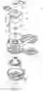
FIG. 1 is a perspective view of a sensorized tensioner according to the invention;
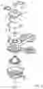
FIG. 2 is an exploded perspective view of the tensioner of FIG. 1;
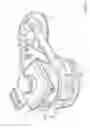
FIG. 3 is a section view of the tensioner of FIG. 1;
FIG. 4 is a diagram illustrating the operation of a method for estimation of the efficiency of the tensioner of FIG. 1;
FIGS. 5 and 6 are graphs representing parameters for estimation of the efficiency of the tensioner of FIG. 1 as a function of the time; and
FIG. 7 is a diagram illustrating the operation of a method for estimation of the efficiency of the tensioner of FIG. 1 according to a closed-loop control.
BEST MODE FOR CARRYING OUT THE INVENTION
With reference to FIGS. 1 to 3, a sensorized tensioner 1 is illustrated comprising a base 2, adapted to be fixed to an engine (not illustrated), an arm 3 and a pulley 4. The arm 3 has an elongated shape and comprises a central body 6 and an end 7 extending distally from the central body 6. The central body 6 is hinged to the base 2 by means of a pin 9 and the end 7 carries a pulley 4 by means of bearings 8. The pulley 4 is configured to cooperate with a belt (not illustrated) of a transmission of the engine.
The tensioner 1 further comprises a spring 5 comprising a first end connected to the body 6 of the arm 3 and to a second end connected to the base 2. The spring 5 is sized so as to provide a predetermined tensioning force to the transmission belt by means of the pulley 4.
The pin 9 is integral with the base 2 and cooperates with a slide bushing 11 coaxial with it and integral with the arm 3. The pin 9 and the arm 3 are axially constrained by means of an elastic element, for example a disc spring 13, preloaded. The tensioner 1 is operatively connected to a base of an internal combustion engine by a screw 12 integral with the pin 9.
Lastly, the tensioner 1 comprises sensor means 14 configured to acquire the value of a plurality of physical quantities relative to some elements of the tensioner 1. Preferably said sensor means 14 comprise a temperature sensor, preferably a thermocouple 16 and a position sensor, preferably a magnet 17.
The tensioner 1 further comprises an electronic unit 20 configured to cooperate with the sensor means 14 in order to collect the values of the physical quantities quantified by the sensor means 14. The electronic unit 20 essentially comprises an electronic circuit 18 configured to cooperate with the temperature sensor and the position sensor and a connector 19 adapted to allow communication of the data collected by the electronic circuit 18 to a control unit of the vehicle (not illustrated).
The electronic circuit 18 may also be configured to process the above-mentioned values and communicate the results to the vehicle control unit according to the method described below in further detail.
The tensioner 1 further comprises a supporting structure 22 having a substantially box-shape and housing inside it the electronic circuit 18. Preferably, the supporting structure 22 is integral with the base 2 and is positioned above the same, namely above the elastic element 13, and is made in two elements, one upper and one lower, which can be opened to house the electronic circuit 18 inside.
The supporting structure 22 comprises, obtained on the upper element, a hole 24 within which a tubular element 25 is housed integrally connected to the arm 3 of the tensioner by means of a flange 23 extending in a cantilever from the distal portion 7 towards the structure 22.
The magnet 17 is conveniently housed inside the tubular element 25, for example it is carried by the bottom surface thereof by means of an interlock coupling. The magnet 17 is configured to interact, by means of the magnetic field it generates, with the electronic circuit 18 in order to identify the position of the arm 3 with respect to the base 2.
The thermocouple 16, in the known art, comprises two metal filaments 21, which connect the electronic circuit 18 to the pin 9 and the bushing 11 respectfully, in order to measure the temperature thereof during use of the tensioner 1. Conveniently the metal filaments 21 pass through the supporting structure 22 and can be conveniently housed in appropriate guides.
The invention further relates to a method for estimation of the state of efficiency of the tensioner 1 by means of the data collected by the sensor means 14.
Preferably said method is an open-loop control, as illustrated in FIG. 4, said method essentially comprising the steps of:
-
- acquiring data (block 27) relative to operating parameters of the tensioner 1;
- calculating a plurality of quantities (block 29) representative of the state of efficiency of the tensioner 1;
- comparing the quantities (block 30) with stored threshold values; and
- activating a signal if the comparison determines a condition of inefficiency of the tensioner 1.
The acquisition of data (block 27) comprises:
-
- the acquisition, via the sensor means 14, of a plurality of quantities relative to operation of the tensioner, such as the temperature T between pin 9 and bushing 11 or the position of the arm 3 (block 32) with respect to the base 2;
- the acquisition of data previously stored in the electronic circuit 18 (or the vehicle control unit) such as the properties of the material of the pin 8 or of the bushing 11 (blocks 34, 35), data relative to the arrangement of the tensioner with respect to the belt transmission system (block 31), geometrical data relative to the tensioner itself (block 34);
- the acquisition of data coming from other sensors of the vehicle, for example data relative to the application (block 32), such as the r.p.m. of the engine, or the percentage of use of the engine at a predetermined velocity %αi and at a predetermined engine load. Calculation of the quantities representative of the state of efficiency of the tensioner 1 (block 29) comprises the steps of:
- calculating the friction coefficients fPB,fSB and the wear coefficients KPB,KSB of the pin 9 and the bushing 11 (block 38), by means of the data coming from the blocks 27, 34, 35, stored in appropriate tables or graphs correlating temperature, pressure and velocity and obtained by experimental means;
- calculating the wear (block 39) δPB,δSB of the pin 9 and/or of the bushing 11 using a wear model (for example Reye's hypothesis) by means of the data coming from the blocks 27, 38;
- calculating the wear and the parallelism as a function of the time by means of an appropriate geometric model of the tensioner (block 40) receiving in input the data coming from the blocks 33 and 39 and correlating the wear of the bushing 11 with the parallelism. Said calculation of wear and parallelism is made using mathematical relationships deduced from experimental tests;
- calculating the axial force acting on the arm 3 by means of an axial force model (block 41) comprising maps of values collected experimentally, receiving in input the data from the block 40 and from a block 42;
- calculating the damping of the tensioner 1 by means of a model (block 42) adapted to calculate the damping of the tensioner, substantially by calculating the acting force multiplied by the application arm thereof and the friction coefficient, and receiving in input data from the blocks 33, 34, 35 and 42;
- estimating the pressure P acting between pin 9 and bushing 8 by means of an experimental free body diagram model (block 43) of the tensioner receiving in input data from the blocks 41, 31 and 33;
- estimating the velocity V of the arm 3 by means of an experimentally processed duty cycle model (block 44). It receives the data from the blocks 32, 33 and the temperature T;
The wear, parallelism and damping values of the tensioner 1 are calculated and updated in real time and are compared with predetermined threshold values (block 30).
FIGS. 5 and 6 give two examples of comparison in real time of said quantities, damping and parallelism respectively, with pre-set threshold values.
FIG. 5 shows the damping, in Nm, as a function of the time, in hours, and a lower threshold value is provided, Sset, below which the damping of the tensioner 1 is considered inadequate.
FIG. 6 shows the parallelism, in mm, as a function of the time, in hours, and an upper threshold value, Pset, is provided above which the parallelism of the tensioner 1 is considered inadequate.
The threshold values can be stored previously on the electronic circuit 18 or in the vehicle control unit.
When the value of the quantity representative of the state of efficiency of the tensioner 1 exceeds an upper and/or lower threshold value, a signal is sent to the vehicle control unit and the state of the tensioner is signalled.
The signalling can be of any known type, for example a light on the dashboard and/or an acoustic alarm.
Preferably prior to said signalling it is also possible to indicate numerically, for example by means of display of the remaining kilometres, the residual life of the tensioner and the signalling will be activated only when a threshold value is exceeded.
FIG. 7 illustrates a variant of the method of FIG. 4, in which a closed-loop control of the parallelism is present.
In this variation the parallelism is measured directly by means of an appropriate proximity sensor //, not illustrated, carried in a known manner by the tensioner 1.
The closed control by means of the proximity sensor // allows greater precision and therefore improved prediction of the remaining life of the tensioner 1.
From an examination of the characteristics of the tensioner described, the advantages that can be obtained are evident.
The use of a tensioner 1 provided with sensor means 14 configured to acquire data relative to the tensioner 1 allows monitoring of the state of the tensioner 1 in real time and notification to the user of a state of inefficiency of the tensioner 1 if the efficiency values exceed a predetermined threshold.
Lastly, it is clear that modifications or variations that do not depart from the protective scope defined by the claims can be made to the tensioner 1 described and to the relative method for estimation of the efficiency illustrated.
For example, the tensioner 1 could be of any type, for example a dual-arm tensioner.
The models for calculation of the parameters indicating the efficiency of the tensioner 1 described above could be different.
The closed-loop control could be realized not only via the proximity sensor but by means of other sensors.
Claims
1. A tensioner comprising:
a base adapted to be secured to an engine,
at least one arm hinged to a pin fixed to said base and bearing a pulley adapted to cooperate with a belt of a transmission of said engine,
elastic means for pushing said at least one arm in a direction so as to keep said pulley against said belt, and
sensor means for acquiring in real time a plurality of data relating to said tensioner to estimate the state of efficiency of the same.
2. The tensioner according to claim 1, wherein said sensor means comprise a temperature sensor and a position sensor for measuring the angular position of said arm with respect to said base.
3. The tensioner according to claim 2, wherein said temperature sensor measures a temperature of or near said pin.
4. The tensioner according to claim 2, wherein the temperature sensor is formed by a thermocouple.
5. The tensioner according to claim 2, wherein said position sensor is carried by said base and interacts with an element carried by said at least one arm.
6. The tensioner according to claim 1, comprising an electronic circuit connected to said sensor means and provided with means for processing signals generated by said sensor means, and a connector to connect said electronic circuit to a control unit of said vehicle.
7. The tensioner according to claim 1, comprising a proximity sensor configured to measure the parallelism of said arm of said tensioner.
8. A method for the estimation of the state of efficiency of a tensioner, the method comprising:
acquiring data relating to operating parameters from the sensor means arranged on the tensioner;
calculating a plurality of quantities representing the state of efficiency of the tensioner on the basis of the acquired data;
comparing said calculated quantities with stored threshold values; and
activating a signal if said comparison determines a condition of inefficiency of the tensioner.
9. The method for the estimation of the state of efficiency of a tensioner according to claim 8, wherein said operating parameters acquired by said sensor means comprise the temperature between a pin and a bushing of said tensioner and the position of an arm with respect to a base of said tensioner.
10. The method according to claim 8, wherein said calculation step comprises:
calculating friction coefficients of said pin and said bushing;
calculating wear parameters of at least one of either said pin or said bushing;
calculating the wear, the parallelism and the damping of said tensioner; and
estimating the pressure P and the velocity V between said pin and said bushing.
11. The method according to claim 8, wherein the condition of inefficiency of the tensioner is represented by the exceeding of a predetermined threshold value (P↓set, S↓set) by said calculated quantities.
12. The method according to claim 8, wherein said method is an open-loop control.
13. The method according to claim 8, wherein said method comprises at least one closed-loop control of one of said quantities representing the state of efficiency of the tensioner.
Images & Drawings included:


Sources:
- United States Patent and Trademark Office - verify current appl. status at the USPTO↗
Similar patent applications:
- » 20160223450
Water tension sensor, system for characterising and continuously measuring soil water, system for indicating critical soil water tension and irrigation rod - » 10388816
Seat belt tension sensor having shock isolation - » 10761134
Seat belt tension sensor - » 10604319
Method of attaching a seat belt to a seat belt tension sensor - » 10653463
Seat belt tension determination using multiple belt tension sensors - » 10691460
Riser tensioner sensor assembly - » 10373172
Seat belt tension sensor assembly - » 10460384
Seat belt tension sensor - » 12286439
Suitcase with internal netting connected to tension sensors for weighing contents - » 10250161
Seat belt tension sensor
Recent applications in this class:
- » 20240247706 2024-07-25
BELT TENSIONER WITH INTEGRATED IDLER PULLEY FOR AN ENDLESS DRIVE BELT OF AN ENGINE - » 20230140725 2023-05-04
Bearing pivot tensioner assembly - » 20220412438 2022-12-29
Tensioning systems and methods - » 20220325783 2022-10-13
DRIVE BELT TENSIONER FOR ELECTRIC VEHICLE - » 20220018421 2022-01-20
Belt tensioning device with a belt drive - » 20190107179 2019-04-11
Friction Type One-Way High Damping Tensioner - » 20180355955 2018-12-13
Variable belt tensioner for engine and method for controlling mild hybrid vehicle using variable belt tensioner for engine - » 20180066733 2018-03-08
Accessory drive tensioner with improved arrangement of tensioner arm and biasing member - » 20180010669 2018-01-11
Magnetic stop for moving components - » 20170002902 2017-01-05
Belt tensioner for a belt drive
Recent applications for this Assignee:
- » 20250224017 2025-07-10
POWER TRANSMISSION BELT AND RELATED TRANSMISSION SYSTEM - » 20240287292 2024-08-29
POWER TRANSMISSION BELT - » 20240167535 2024-05-23
POWER TRANSMISSION BELT AND ITS TRANSMISSION SYSTEM - » 20240157930 2024-05-16
METHOD FOR CONTROLLING A HYBRID POWERTRAIN AND HYBRID POWERTRAIN OPERATING ACCORDING TO SUCH A METHOD - » 20240011550 2024-01-11
Filtering pulley - » 20230417312 2023-12-28
Filtering pulley - » 20230258247 2023-08-17
Tensioner for an accessory drive of a motor vehicle and accessory drive including such a tensioner - » 20230167892 2023-06-01
Filtering pulley - » 20230167883 2023-06-01
IMPROVED FILTERING PULLEY, SYSTEM COMPRISING SUCH PULLEY AND RELATED CONTROL METHOD - » 20230104355 2023-04-06
TENSIONER FOR AN ACCESSORY DRIVE OF A MOTOR VEHICLE AND ACCESSORY DRIVE INCLUDING SUCH A TENSIONER