Spring loaded quick release system
US20200088488A1
2020-03-19
16/569,822
2019-09-13
✅ Patent granted
US 10,921,082 B2
2021-02-16
-
-
Stephen Johnson
Jacobson Holman PLLC
2039-09-13
Abstract:
The invention provides a quick release mechanism that allows two component parts to be connected to and disconnected from each other easily. In particular the invention provides a clip on and off system that allows two components to be connected together at the push of a button. The invention is particularly intended as a quick release system for the attachment of a firearm to a bipod.
Assignee:
- Backlanz Limited 1 🇳🇿 lnvercargill, New Zealand
- BACKLANZ LIMITED 1 🇳🇿 Invercargill, New Zealand
Applicant:
Interested in similar patents?
Get notified when new applications in this technology area are published.
Classification:
F41A23/10 » CPC main
Gun mountings, e.g. on vehicles; Disposition of guns on vehicles; Mountings without wheels; Bipods adjustable
F41A23/52 » CPC further
Gun mountings, e.g. on vehicles; Disposition of guns on vehicles Base plates for gun mountings
Description
FIELD OF THE INVENTION
The invention provides a quick release mechanism that allows two component parts to be connected to and disconnected from each other easily. In particular the invention provides a clip on and off system that allows two components to be connected together at the push of a button. The invention is particularly intended as a quick release system for the attachment of a firearm to a bipod.
BACKGROUND TO THE INVENTION
When using a firearm in conjunction with a bipod, it is much easier to keep the bipod detached from the firearm when not in use. It is a lot easier to carry as it does not dig into a wearer's back when slung over their shoulder whilst being carried or and it does not get stuck on a backpack or caught on any bush the shooter maybe traveling through. Having the bipod disconnected also makes the firearm a lot lighter when the shooter wants to perform a shot from a standing position.
The problem for the firearm user is that once he or she wants to use the firearm with the bipod attached, they must secure the two together which often takes time and is cumbersome. The present invention was created to make a bipod more easily connected to a firearm and to give the shooter the option of keeping the bipod detached.
OBJECT OF THE INVENTION
It is therefore an object of this invention to provide a simple system where a firearm can be attached and detached from a bipod, or to at least provide the user with a choice.
SUMMARY OF THE INVENTION
The invention provides a spring-loaded quick release mechanism which allows two components to be connected and disconnected quickly at the push of a button. A first component is preferably a firearm, and a second component is preferably a bipod. Alternatively, one component may be a tripod and another component may be a camera or other piece of equipment.
When connected, the components are held firmly together by forces generated by the spring of the quick-release system but whilst being held firmly together, rotation and pivoting are still possible.
The invention provides a spring-loaded quick release mechanism comprising: a ball pin attached to a first component;
a quick-release mechanism attached to a second component; and whereby
upon engagement between the ball pin and the quick-release mechanism the first and second components are releasably attached.
Preferably the quick-release mechanism comprises a compression spring which spring loads the quick-release mechanism when a force is applied to the mechanism either by the ball pin or a latch on the quick-release mechanism being depressed. This quick-release mechanism, or spring-loaded latch is a key feature of the invention in firmly holding the first and second components together. This mechanism may be made from a variety of materials, although metal has advantages over plastics as the components then slide over each other more smoothly. The mechanism may be 3D printed.
The ball pin is preferably of a specific length to allow the quick-release mechanism, when depressed, to engage onto the ball pin to thus maintain the compression spring under compression. The ball pin may be adjustable in length which allows varying degrees of tension to be applied to the two components which are being held together.
The ball pin may be attached to a mounting bracket which is itself attached to the underside of a first component. The first component is preferably a firearm.
The mounting bracket may be 3D printed in metal, and preferably stainless steel. This makes it light in weight.
The quick-release mechanism may be housed in a latch housing which may be held onto the bipod by mounting screws. The latch housing may be 3D printed in metal and more preferably in stainless steel, but it could alternatively be printed, machined or injection moulded in a plastic.
The housing may include a centre locator.
The housing may include a lip mechanism to prevent the latch from overloading.
However, within the scope of the invention is included a housing manufactured in a single piece with a second component (such as the bipod). In this instance, the bipod and housing would not be screwed together.
The quick-release mechanism preferably includes a push button for release, which, when depressed, disengages the ball pin from the quick-release latch, detaching the bipod from the mounting bracket.
The invention proves a method of releasably attaching a bipod to a firearm comprising the use of a spring-loaded quick-release mechanism as described in this specification.
It is acknowledged that the terms “comprise”, “comprises” and “comprising” may, under varying jurisdictions, be attributed with either an exclusive or an inclusive meaning. For the purpose of this specification, and unless otherwise noted, these terms are intended to have an inclusive meaning—i.e. they will be taken to mean an inclusion of not only the listed components which the use directly references, but also to other non-specified components or elements.
DESCRIPTION OF THE DRAWINGS
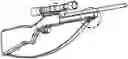
FIG. 1 consists of FIGS. 1 and 1A, FIG. 1 is a view of the mounting bracket fitted to a firearm with a sling attached to the stop block; and
FIG. 1A is a close up view of the mounting bracket fitted to a firearm;
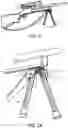
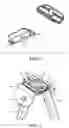
FIG. 2 consists of FIGS. 2 and 2A, FIG. 2 is a view of a bipod with latch engaged onto the mounting bracket—legs down; and
FIG. 2A is a close up view of a bipod with latch engaged onto the mounting bracket—legs down;
FIG. 3 consists of FIGS. 3 and 3A, FIG. 3 is a view of a bipod with latch fitted engaged onto the mounting bracket—legs up; and
FIG. 3A is a close up view of a bipod with latch fitted engaged onto the mounting bracket—legs up;
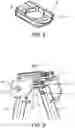
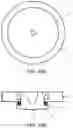
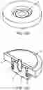
FIG. 4 shows a mounting bracket. Although this is shown with a curved surface, the surface could be flat right across without sloped edges. It is not essential that the housing comprises a centre locator or lips to prevent the latch from overloading;
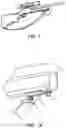
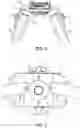
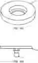
FIG. 5 is a view of the latch housing fitted to a bipod;
FIG. 6 is a front view of the latching mechanism and latch housing fitted to a bipod;
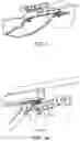
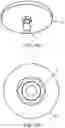
FIG. 7 is a view from underneath of the latching mechanism and latch housing fitted to a bipod with a mounting bracket attached;
FIG. 8 is a view of the latching mechanism fitted to a bipod and the latch housing detached;
FIG. 9 is a view of the latching mechanism engaged onto the mounting bracket;
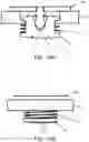
FIG. 10 consists of 10A-10M which show various components and views; and
FIG. 10A shows components 21 and 22; and
FIG. 10B shows component 21 with the latch depressed; and
FIG. 10C shows component 21 without a latch; and
FIG. 10D shows component 22; and
FIG. 10E shows component 22; and
FIG. 10F shows component 21 with latch; and
FIG. 10G shows component 21 with latch; and
FIG. 10H shows a sectional view; and
FIG. 10K shows a side sectional view; and
FIG. 10M shows a side view.
DETAILED DESCRIPTION OF THE INVENTION
Description of Parts:
Mounting bracket 1. This is used to accommodate the ball pin 2. The bracket is mounted onto the stock of a firearm with the ball pin. This ensures a centralised mounting point and fewer components.
Ball pin 2. This connects the bracket 1 that is attached to the firearm to the quick release latch 12 that is fitted to the bipod. The ball pin is of a certain length to allow the quick release latch 12 when depressed, to engage onto the ball pin 2 and keep a spring 11 under compression when released. The ball pin 2 transfers force from the mounting bracket 1 into the spring-loaded latch 12 allowing the firearm to pivot side to side with movement of the spring 11.
Stop block 3. The purpose of the stop block is to catch on the lip of the latch housing 6 to prevent the latch from being overloaded with leverage forces from the bipod legs. The stop block also locates the mounting bracket in slots on the latch housing. The forward stop block also holds the centre lock on the latch housing. This is an advantage because it allows the firearm to pan horizontally side to side.
There is provided a hole in the stop block to allow the attachment of a sling, strap or the like that is used to carry the firearm over a user's shoulder.
Attachment means for bipod legs, in this embodiment shown as bipod leg pivot bolts. These allow the legs to be folded up and down into position.
Latch Housing 6. This is used to hold the hexagonal nut that holds the quick release latch 12. The quick release latch travel travels up and down in the hexagonal hole. When the mounting bracket 1 and the bipod 14 are connected the latch housing acts as a spacer allowing the mounting bracket 1 to hold firmly against the latch housing with the pressure that is generated by the spring 11. Angled surfaces rest against the mounting bracket so the bipod naturally wants to point longitudinally on the rifle but will allow panning of the rifle if force is applied.
Lips on housing 7. These are to stop any excessive forces being applied to spring loaded latch 12 preventing it from failing.
Mounting bracket guide slots 8. This is used to help locate the stops on the mounting bracket 1 in the correct location to rotate under the lips 7 on the latch housing. This is an advantage as it helps locate the bipod in the correct position when mounting it to the rifle.
Centre lock 9. This locates the bipod parallel with the rifle to prevent the bipod from spinning when the bipod is in the legs up position. The forces on the spring-loaded latch 12 holds the stop 3 in the centre lock. When the bipod is in use on the rifle and forward pressure is applied the movement from the spring-loaded latch allows the stop on the mounting bracket 1 to lift up out of the centre lock. This then allows the rifle to pan horizontally.
Latch housing mounting screws 10. These hold the latch housing 6 and bipod 11 together.
Multi wave compression spring 11. This is used to spring load the quick release latch 9 when a force is applied to the quick release latch 9 either through the ball pin or the latch being depressed by hand, the spring 8 compresses and depresses allowing the latch to slide up and down through clearance hole in the bipod and the latch housing 6 allowing a range of movement for the bipod. Having the latch spring loaded holds the bipod firmly against the mounting plate eliminating any unnecessary movement unless a force is applied to compress the spring. For the latch to be engaged onto the ball pin the latch is depressed by hand until it is engaged onto the ball pin, When the hand pressure is released the spring pulls the mounting bracket 1 and the bipod and latch housing together 6.
Quick release clip on and off latch 12. This is used to engage onto the ball pin 2 and hold the bipod 14 attached to the latch housing 6 and mounting bracket 1 together. The multi wave compression spring 11 is fitted over the body of the quick release latch 12 and sits between the bottom side of the bipod 14 and the flanged end of the latch. During manufacturing assembly, the latch is fitted through the clearance hole in the bipod and screwed into a low-profile nut on the top side of the bipod that is held in place on the inside of the latch housing 6. When the latch is fitted through the clearance hole in the bipod and screwed into the low profile nut the spring 11 becomes under compression. The latch travels up and down inside the latch housing inside the hexagonal hole when load is applied through it being pushed and pulled by the ball pin 2 when it is engaged into the spring-loaded latch. For example, the firearm is able to be canted side to side as this movement is transferred through the ball pin and into the spring-loaded quick release latch. The latch also allows rotational movement.
Push button release 13. This button is located on the latch and when it is depressed it disengages the ball pin from the quick release latch, detaching the bipod from the mounting bracket 1 attached to the firearm stock.
Bipod bracket 14. This accommodates the quick release latch 12, the latch housing 6 and the bipod legs 15.
Bipod legs 15. Provide the stable platform to shoot off—shown for perspective.
Referring now to FIGS. 10 A-M, there is shown:
Component 22 is attached to component 21. The ball pin 2 is apart or attached to component 22 that is used to connect component 21 and 22 together.
Ball pin 2 holds component 21 and 22 together when the ball pin is engaged into the quick release latch 12. The ball pin is of a certain length to allow the quick release latch 12 when depressed, to engage onto the ball pin 2 and keep a spring 11 under compression when released. The ball pin 2 transfers force from the component 22 into the spring-loaded latch 12 allowing rotational movement. The Ball pin 2 can be fastened to component 22 or even manufactured as one whole piece so the ball pin and component 22 are one component.
Component 21 accommodates the quick release latch 12. Component 21 has a hole the latch can slide through. Component 21 has clearance hole that allows the low-profile nut on the quick release latch 12 to slide up and down in. The low-profile nut sits at the bottom of the clearance hole and holds the latch in place. This stops the latch from falling through the Component.
Multi wave compression spring 11. This is used to spring load the quick release latch 12. When a force is applied to the quick release latch either through the ball pin or the latch being depressed by hand, the spring 11 compresses and depresses allowing the latch to slide up and down through clearance hole in component 21 allowing a range for component 22. Having the latch spring loaded holds component 21 firmly against the component 22 eliminating any unnecessary movement unless a force is applied to compress the spring. For the latch to be engaged onto the ball pin the latch is depressed by hand until it is engaged onto the ball pin 2, When the hand pressure is released the spring pulls Component 21 and Component 22 together
Quick release clip on and off latch 12. This is used to engage onto the ball pin 2 and hold component 21 and component 22 together. The multi wave compression spring 11 is fitted over the body of the quick release latch 12 and sits between the bottom side of the component 21 and the flanged end of the latch. During manufacturing assembly, the latch is fitted through the clearance hole in component 21 and screwed into a low-profile nut on the top side of component 21. When the latch is fitted through the clearance hole in the bipod and screwed into the low profile nut the spring 11 becomes under compression. The latch travels up and down inside the clearance hole component 21 when load is applied through it being pushed and pulled by the ball pin 2 attached to component 22 when it is engaged into the spring-loaded latch. Component 21 and component 22 can also rotate whilst being held firmly together.
Push button release 13. This button is located on the latch and when it is depressed it disengages the ball pin from the quick release latch, detaching Component 21 from component 22.
How to operate latching mechanism:
-
- 1. Rotate the mounting bracket stop blocks 3&4 into the guide slots 8 in the latch housing 6. The ball pin that is attached to the mounting bracket will now sit in the hole of the quick release latch 12.
- 2. From underneath apply force to the outside edges of the latch so the latch travels up through the latch housing and engages onto the ball pin. When it engages a click will be heard.
- 3. Operate the bipod as desired.
- 4. To horizontally pan apply forward pressure to the firearm until the stop block 3 comes out of the centre lock 9.
- 5. To disconnect, depress the button on the latch 10 and the bipod will detach.
It will be appreciated that whilst the invention has been described with reference to a specific embodiment and a specific use of the spring-loaded quick release mechanism, it may be used in other situations. When the latching mechanism was created it was realised this system could also be used on the likes of cameras/spotting scope and tripod by means of fixing a mounting bracket into the bottom of the camera/spotting scope and the latching system into the tripod. Having a mounting bracket for multiple items will also make the bipod or tripod universal as you could interchange the items. It is possible that this latching mechanism could be used on backpacks to allow the firearm or any other item to connect and disconnect from the backpack. Designs of other products such as tripod do not have the pivot block that slots into the latch housing allowing 360-degree rotation.
Claims
1. A spring-loaded quick release mechanism which allows two components to be connected and disconnected quickly at the push of a button and wherein when connected, the components are held firmly together by forces generated by the spring of the quick-release system but whilst being held firmly together, rotation and pivoting are still possible.
2. A spring-loaded quick release mechanism according to claim 1, wherein a first component is a firearm, and a second component is a bipod.
3. A spring-loaded quick release mechanism comprising: a ball pin attached to a mounting bracket on a first component; a quick-release mechanism attached to a second component; and whereby upon engagement between the ball pin and the quick-release mechanism the first and second components are releasably attached.
4. A device according to claim 1, wherein the quick-release mechanism comprises a compression spring which spring loads the quick-release mechanism when a force is applied to the mechanism either by the ball pin or a latch on the quick-release mechanism being depressed.
5. A device according to claim 1, wherein the ball pin is of a specific length to allow the quick-release mechanism, when depressed, to engage onto the ball pin to thus maintain the compression spring under compression.
6. A device according to claim 1, wherein the ball pin is adjustable, allowing the tension on the components to be varied.
7. A device according to claim 1, wherein the ball pin is attached to a mounting bracket which is itself attached to the underside of the first component.
8. A device according to claim 1, wherein the mounting bracket is 3D printed any metal or plastic.
9. A device according to claim 1, wherein the quick-release mechanism is housed in a housing, which is held onto the bipod by mounting screws.
10. A device according to claim 1, wherein the housing and bipod are manufactured in a single piece and are not screwed together.
11. A device according to claim 1, wherein the quick-release mechanism includes a push button for release, which, when depressed, disengages the ball pin from the quick-release latch, detaching the bipod from the mounting bracket.
12. A device according to claim 1, wherein one component is a tripod and the other component is selected from the group comprising: a camera, firearm, a torch, a spotting scope, backpack, and a door latch.
Images & Drawings included:
Sources:
- United States Patent and Trademark Office - verify current appl. status at the USPTO↗
Recent applications in this class:
- » 20250257969 2025-08-14
ADJUSTABLE BIPOD - » 20250216167 2025-07-03
Motorized Extension for a Bipod Gun Support - » 20250198720 2025-06-19
Rible Bipod Feet - » 20250123071 2025-04-17
FIREARM SHOOTING REST - » 20250116474 2025-04-10
ACCESSORY MOUNT - » 20250027736 2025-01-23
Adjustable bipod - » 20240410669 2024-12-12
CENTER HEIGHT ADJUSTABLE SHOOTING STICKS FOR MOUNTAINOUS TERRAIN - » 20240302123 2024-09-12
BIPOD WITH SLING STUD MOUNT - » 20240263906 2024-08-08
BIPOD FOR A SMALL ARMS WEAPON, VARIABLY SELECTABLE SURFACE INTERFACE APPARATUS, AND METHOD FOR RECONFIGURING SAME - » 20240240905 2024-07-18
BIPOD