Sound device
US20200213767A1
2020-07-02
16/702,549
2019-12-04
✅ Patent granted
US 11,109,161 B2
2021-08-31
-
-
Andrew L Sniezek
W&G Law Group LLP
2040-01-05
Abstract:
The present invention provides a sound device, which includes a bottom plate, a support fixed to the bottom plate, a frame arranged on the support, and a diaphragm fixed to the frame. The sound device further includes a first piezoelectric ceramic sheet and a second piezoelectric ceramic sheet that are disposed separately on the support, and the first piezoelectric ceramic sheet and the second piezoelectric ceramic sheet are respectively provided with a transmission member abutting against the diaphragm. The sound device in the present disclosure can increase a driving force, increase a vibration amplitude, enhance a product sensitivity, broaden a response range, increase a driving fulcrum, improve a vibration balance, and avoid a product distortion.
Inventors:
- Bo Xiao 69 🇨🇳 SHENZHEN, China
- Ronglin Linghu 58 🇨🇳 Shenzhen, China
- Xiaodong Liu 19 🇨🇳 Shenzhen, China
Assignee:
- AAC TECHNOLOGIES PTE. LTD 958 🇸🇬 Singapore, Singapore
Applicant:
Interested in similar patents?
Get notified when new applications in this technology area are published.
Classification:
H01L41/187 » CPC further
Piezo-electric devices in general; Electrostrictive devices in general; Magnetostrictive devices in general; Processes or apparatus specially adapted for the manufacture or treatment thereof or of parts thereof; Details thereof; Selection of materials for piezo-electric or electrostrictive devices, e.g. bulk piezo-electric crystals Ceramic compositions, i.e. synthetic inorganic polycrystalline compounds incl. epitaxial, quasi-crystalline materials
H04R1/026 » CPC further
Details of transducers, loudspeakers or microphones; Casings; Cabinets ; Supports therefor; Mountings therein Supports for loudspeaker casings
H04R1/02 IPC
Details of transducers, loudspeakers or microphones Casings; Cabinets ; Supports therefor; Mountings therein
H04R17/00 » CPC main
Piezo-electric transducers; Electrostrictive transducers
Description
TECHNICAL FIELD
The present disclosure relates to electroacoustic devices, in particular to a sound device.
BACKGROUND
A sound device is an electroacoustic device that converts an audio electrical signal into a sound signal, and is widely used in communication terminal devices such as a mobile phone, a fixed telephone, and an earphone, to realize an audio output.
A driving structure composed of a voice coil and a magnetic steel is usually used in common sound devices. The voice coil is energized to generate an electromagnetic induction force with the magnetic steel, thus driving a diaphragm to vibrate and sound.
The sound device in related technologies adopts a piezoelectric ceramic sheet as the driving structure to replace a combination of the voice coil and the magnetic steel. The piezoelectric ceramic sheet is provided with a transmission member abutting against the diaphragm, and a deformation generated by energizing the piezoelectric ceramic sheet is transmitted to the diaphragm through the transmission member, thereby driving the diaphragm to vibrate and sound. However, an abutting position between the single transmission member and the diaphragm is very critical, because a poor abutting position easily causes the diaphragm to suffer from a poor vibration, a distortion, an insufficient driving force and a poor sensitivity.
Therefore, it is necessary to provide a new sound device with an improved driving structure.
BRIEF DESCRIPTION OF THE DRAWINGS
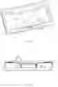
FIG. 1 is a schematic exploded perspective structural view of a sound device in the present disclosure;
FIG. 2 is a schematic partial perspective structural view of the sound device in the present disclosure;
FIG. 3 a schematic sectional structural view of the sound device in the present disclosure.
DETAILED DESCRIPTION
The present disclosure is further described in detail below with reference to accompanying drawings and specific embodiments in order to provide a better understanding of a solution of the present disclosure and advantages in various aspects. Further, the following specific embodiments are provided to facilitate a clearer understanding of the contents of the present disclosure, not to limit the present disclosure.
As shown in FIGS. 1 to 3, the present disclosure provides a sound device which includes a bottom plate 1, a support 2 fixed to the bottom plate 1, a first piezoelectric ceramic sheet 3 and a second piezoelectric ceramic sheet 4 that are disposed separately on the support 2, a frame 5 arranged on the support 2, a diaphragm 9 fixed to the frame 5, and a front cover 10 pressed on the diaphragm 9.
Both the support 2 and the frame 5 are hollow annular members. An outer contour of an orthogonal projection of the support 2 on the bottom plate 1 coincides with an outer contour of an orthogonal projection of the frame 5 on the bottom plate 1, and an inner contour of an orthogonal projection of the support 2 on the bottom plate 1 is closer to a center side than an inner contour of an orthogonal projection of the frame 5 on the bottom plate 1. The first piezoelectric ceramic sheet 3 and the second piezoelectric ceramic sheet 4 are provided with a pressing block 6 abutting against an inner wall surface of the frame 5, and the pressing block 6 presses the first piezoelectric ceramic sheet 3 and the second piezoelectric ceramic sheet 4 against the support 2. A transmission member 7 is further respectively arranged at a central region of the first piezoelectric ceramic sheet 3 and at a central region of the second piezoelectric ceramic sheet 4, and the transmission member 7 abuts against the diaphragm 9. The first piezoelectric ceramic sheet 3 and the second piezoelectric ceramic sheet 4 are connected in parallel to drive the diaphragm 9. Preferably, the first piezoelectric ceramic sheet 3 and the second piezoelectric ceramic sheet 4 are arranged in parallel. A deformation generated by energizing the piezoelectric ceramic sheet is transmitted to the diaphragm 9 through the transmission member 7.
Further, the diaphragm 9 includes a dome 91 and a folded ring 92 bent and extending from the dome 91. The dome 91 and the folded ring 92 may be a separate structure or an integrated structure. The transmission member 7 is columnar and abuts against the dome 91 of the diaphragm 9.
In this embodiment, the first piezoelectric ceramic sheet 3 and the second piezoelectric ceramic sheet 4 are connected by a connecting member 8. Preferably, the connecting member 8 is arranged on an outer wall surface of the frame 5 and connects the first piezoelectric ceramic sheet 3 and the second piezoelectric ceramic sheet 4. In other embodiments, the connecting member 8 may alternatively be arranged on the outer wall surface of the support 2. The connecting member 8 may be used as an electrical connecting terminal of the piezoelectric ceramic sheet, and may further ensure a relative position between the two piezoelectric ceramic sheets. The forgoing description is only for an illustrative purpose and is not to be construed as limiting the present disclosure.
Comparing with existing technologies, the sound device in the present disclosure can increase a driving force, increase a vibration amplitude, enhance a product sensitivity, broaden a response range, increase a driving fulcrum, improve a vibration balance, and avoid a product distortion.
It should be noted that, for those skilled in the art, various changes and modifications may be made without departing from the inventive concept of the present disclosure, and all these changes and modifications fall within the protection scope of the present disclosure.
Claims
What is claimed is:1. A sound device, comprising a bottom plate, a support fixed to the bottom plate, a frame arranged on the support, and a diaphragm fixed to the frame, wherein the sound device further comprises a first piezoelectric ceramic sheet and a second piezoelectric ceramic sheet that are disposed separately on the support, and the first piezoelectric ceramic sheet and the second piezoelectric ceramic sheet are respectively provided with a transmission member abutting against the diaphragm.
2. The sound device in accordance with claim 1, wherein the first piezoelectric ceramic sheet and the second piezoelectric ceramic sheet are arranged in parallel.
3. The sound device in accordance with claim 1, wherein the first piezoelectric ceramic sheet and the second piezoelectric ceramic sheet are connected by a connecting member arranged on an outer wall surface of the frame or the outer wall surface of the support.
4. The sound device in accordance with claim 1, wherein the first piezoelectric ceramic sheet and the second piezoelectric ceramic sheet are connected in parallel.
5. The sound device in accordance with claim 1, wherein the first piezoelectric ceramic sheet and the second piezoelectric ceramic sheet are further provided with a pressing block, and the pressing block presses the first piezoelectric ceramic sheet and the second piezoelectric ceramic sheet against the support.
6. The sound device in accordance with claim 1, wherein the diaphragm comprises a dome and an folded ring arranged around the dome, and the transmission member is columnar and abuts against the dome.
7. The sound device in accordance with claim 1, wherein the transmission member is respectively arranged at a central region of the first piezoelectric ceramic sheet and at a central region of the second piezoelectric ceramic sheet.
Images & Drawings included:


Sources:
- United States Patent and Trademark Office - verify current appl. status at the USPTO↗
Similar patent applications:
- » 20140318348
SOUND PROCESSING DEVICE, SOUND PROCESSING METHOD, PROGRAM, RECORDING MEDIUM, SERVER DEVICE, SOUND REPRODUCING DEVICE, AND SOUND PROCESSING SYSTEM - » 20120051550
SOUND RECORDING DEVICE, SOUND PLAYBACK DEVICE, AND SOUND RECORDING/PLAYBACK DEVICE - » 20160035365
SOUND ENCODING DEVICE, SOUND ENCODING METHOD, SOUND DECODING DEVICE AND SOUND DECODING METHOD - » 20130021502
SOUND CORRECTOR, SOUND RECORDING DEVICE, SOUND REPRODUCING DEVICE, AND SOUND CORRECTING METHOD - » 20090066798
Sound corrector, sound recording device, sound reproducing device, and sound correcting method - » 20100030562
Sound determination device, sound detection device, and sound determination method for determining frequency signals of a to-be-extracted sound included in a mixed sound - » 20190028077
Sound processing device, sound control device, and sound control method - » 20200204918
Sound device and electronic device using sound device - » 20100215191
SOUND DETERMINATION DEVICE, SOUND DETECTION DEVICE, AND SOUND DETERMINATION METHOD - » 20250039630
SOUND GENERATION DEVICE, SOUND REPRODUCTION DEVICE, AND SOUND GENERATION METHOD
Recent applications in this class:
- » 20250280244 2025-09-04
Apparatus - » 20250274716 2025-08-28
VIBRATION GENERATING MODULE, SOUND APPARATUS COMPRISING THE SAME, AND VEHICULAR APPARATUS - » 20250247653 2025-07-31
LOUDSPEAKERS - » 20250240577 2025-07-24
Shear Mode Transducer and Methods - » 20250220358 2025-07-03
SOUND OUTPUT APPARATUS - » 20250211917 2025-06-26
PIEZOELECTRIC ACOUSTIC TRANSDUCER, MANUFACTURING METHOD OF PIEZOELECTRIC ACOUSTIC TRANSDUCER - » 20250211916 2025-06-26
VIBRATION DRIVING APPARATUS - » 20250203296 2025-06-19
DISPLAY DEVICE WITH PIEZOELECTRIC ACTUATOR - » 20250203295 2025-06-19
VIBRATION APPARATUS AND APPARATUS INCLUDING THE SAME - » 20250175743 2025-05-29
ACOUSTIC APPARATUS
Recent applications for this Assignee:
- » 20250106561 2025-03-27
MICROELECTROMECHANICAL SYSTEM MEMBRANE - » 20250042724 2025-02-06
CAPACITIVE SENSING CIRCUIT AND CAPACITIVE SENSING METHOD - » 20240284120 2024-08-22
Acoustic transducer and method for manufacturing acoustic transducer - » 20240284119 2024-08-22
Acoustic transducer and method for manufacturing acoustic transducer - » 20240236551 2024-07-11
LOUDSPEAKER ASSEMBLY AND HAND-HELD DEVICE - » 20240236550 2024-07-11
Sound reproducing apparatus and method - » 20240223942 2024-07-04
Speaker module - » 20240223941 2024-07-04
Speaker module - » 20240223937 2024-07-04
Speaker module - » 20240214749 2024-06-27
MEMS OPTICAL MICROPHONE