Methods for optimizing bunch distance of fractured horizontal wells of shale gas
US20200225384A1
2020-07-16
16/837,078
2020-04-01
✅ Patent granted
US 10,761,241 B2
2020-09-01
-
-
Brian S Cook
IPro, PLLC
2040-04-01
Abstract:
The present disclosure provides a method for optimizing bunch distance of fractured horizontal wells of shale gas, which relates to the technical field of oil exploration. The method comprises first establishing a stress field distribution model for a single fracture; then establishing an induced stress distribution model of segmented single-bunch fracturing for a horizontal well; later establishing an induced stress distribution model of segmented multi-bunch fracturing for a horizontal well; last optimizing fracturing parameters and fracture distance according to the distribution pattern of the induced stress difference.
The method considers the stress barrier, stress interference effects, and the variation of the effective net pressure during the synchronous expansion of fractures, so the calculation model is more in line with the actual working conditions, has higher precision, and can provide more accurate theoretical guidance for the optimization design of segmented multi-bunch fracturing of a horizontal well.
Inventors:
- MING YUE 14 🇨🇳 BEIJING, China
- Weiyao ZHU 9 🇨🇳 Beijing, China
- DEBIN KONG 7 🇨🇳 Beijing, China
- YUWEI LIU 1 🇨🇳 Beijing, China
- WENCHAO LIU 5 🇨🇳 Beijing, China
- YUNFENG LIU 9 🇨🇳 Beijing, China
Assignee:
- UNIVERSITY OF SCIENCE AND TECHNOLOGY BEIJING 123 🇨🇳 Beijing, China
Applicant:
Interested in similar patents?
Get notified when new applications in this technology area are published.
Classification:
G01V99/005 » CPC main
Subject matter not provided for in other groups of this subclass Geomodels or geomodelling, not related to particular measurements
E21B43/26 » CPC further
Methods or apparatus for obtaining oil, gas, water, soluble or meltable materials or a slurry of minerals from wells; Methods for stimulating production by forming crevices or fractures
E21B2200/20 » CPC further
Special features related to earth drilling for obtaining oil, gas or water Computer models or simulations, e.g. for reservoirs under production, drill bits
G01V99/00 IPC
Subject matter not provided for in other groups of this subclass
E21B49/00 » CPC further
Testing the nature of borehole walls; Formation testing; Methods or apparatus for obtaining samples of soil or well fluids, specially adapted to earth drilling or wells
Description
CROSS-REFERENCE TO RELATED APPLICATIONS
The present application claims the benefit of Chinese Patent Application No. Application No. 201910137958.8 filed on Feb. 25, 2019, the contents of which are hereby incorporated by reference.
TECHNICAL FIELD
The present disclosure relates to the technical field of oil exploration and is more particularly concerned with a method for optimizing bunch distance of fractured horizontal wells of shale gas.
BACKGROUND
Shale gas has developed rapidly around the world, and its distribution area is also quite wide, showing the features of great developing potential. At present, shale gas resources have been found in such area as Bohai Gulf, Songliao, and Sichuan in China. According to related prediction and speculation, the total amount of shale gas resources in China would exceed 30×1012 m3, which has enormous developing potential.
Shale gas reservoirs show the characteristics of low porosity, and the permeability of substrate is quite low. During the exploration of shale gas, fracture is the major technology and plays an important role in the development of shale gas.
SUMMARY
The present disclosure provides a method for optimizing bunch distance of fractured horizontal wells of shale gas, comprising establishing a stress field distribution model for a single fracture; establishing an induced stress distribution model of multi-segment single-bunch fracturing for a horizontal well; establishing an induced stress distribution model of multi-segment multi-bunch fracturing for a horizontal well; calculating the induced stress outside a fracture in a segment adjacent to previous fractured segment; calculating the induced stress between fractures inside a segment; calculating the induced stress outside a fracture in a segment adjacent to next fractured segment; calculating the horizontal induced stress difference of segmented multi-bunch fracturing for a horizontal well; according to the induced stress difference, determining the optimal bunch distance.
According to at least an embodiment of the present disclosure, the stress field distribution model for a single fracture is
{ σ h = p n ( 1 - a 2 r ( a 2 r ) 2 + 1 4 + a 2 r 4 ( ( a 2 r ) 2 + 1 4 ) 3 ) σ H = 2 p n v ( 1 - a 2 h ( a 2 r ) 2 + 1 4 )
- where σh is the induced stress in the minimum horizontal geostress direction of a fracture, MPa;
- σH is the induced stress in the maximum horizontal geostress direction of a fracture, MPa; pn is original net pressure in fractures, MPa; a is the distance from the fracture center to a measuring point, m; r is fracture half length, m; v is rock Poisson ratio.
According to at least an embodiment of the present disclosure, the induced stress distribution model of multi-segment single-bunch fracturing for a horizontal well comprises: the actual net pressure inside the fracture of the Nth segment, i.e. effective net pressure
p e n ( N ) = p n - ∑ i = 1 N - 1 σ h i ( N )
where pen (N) is the effective net pressure in the fracture of the Nth segment, MPa; pn is the original pressure in the fracture of the Nth segment, MPa; σhi(N) is the induced stress in the minimum horizontal geostress direction generated by the fracturing of the ith segment in the fracture of the Nth segment, MPa.
The horizontal induced stress in the formation around the fracture of the Nth segment is
{ σ h N = p e n ( N ) ( 1 - a 2 r ( a 2 r ) 2 + 1 4 + a 2 r 4 ( ( a 2 r ) 2 + 1 4 ) 3 ) σ H N = 2 p e n ( N ) v ( 1 - a 2 r ( a 2 r ) 2 + 1 4 )
where σhN is the induced stress in the minimum horizontal geostress direction generated by the fracturing of the Nth segment to the formation around the Nth segment, MPa; σHN is the induced stress in the maximum horizontal geostress direction generated by the fracturing of the Nth segment to the formation around the Nth segment, MPa.
After the fracturing of the Nth segment, the total induced stress in the formation around the segment is obtained by superimposing the induced stresses generated by each segment fracture at the point:
{ σ h ′ = ∑ i = 1 N σ h i σ H ′ = ∑ i = 1 N σ H i
where σ′h is the induced stress in the formation around the segment in the minimum horizontal geostress direction after the fracturing of the Nth segment, MPa; σ′H is the induced stress in the formation around the segment in the maximum horizontal geostress direction after the fracturing of the Nth segment, MPa; σhi is the induced stress in the minimum horizontal geostress direction generated by the fracturing of the ith segment to the point, MPa; σHi is the induced stress in the maximum horizontal geostress direction generated by the fracturing of the ith segment to the point, MPa.
According to at least an embodiment of the present disclosure, establishing an induced stress distribution model of multi-segment multi-bunch fracturing for a horizontal well comprises calculating the effective net pressure of the first fracture in the segment relative to previous fractured segment, calculating the effective net pressure of each fracture in the segment relative to the left- and right-side formation thereof, and calculating the effective net pressure of the last fracture in the segment relative to next fractured segment.
According to at least an embodiment of the present disclosure, the multiple bunches are three bunches per segment, wherein the three bunches of fractures of the Nth segment are sequentially recorded as fractures N1, N2 , and N3, Fracture N1 is the fracture near the previous fractured segment, i.e. the (N−1)th fractured segment, Fracture N3 is the fracture the furthest away from the (N−1)th fractured segment, Fracture N2 is the fracture between fracture N1 and fracture N3.
According to at least an embodiment of the present disclosure, the said multi-segment is segments of natural numbers equal to or greater than 3.
According to at least an embodiment of the present disclosure, the effective net pressure of Fracture N1 relative to the previous fractured segment is
penl(N1)=pn−σh(n−1)3(N1)
where penl(N1) is the effective net pressure of Fracture N1 relative to the left-side formation thereof, MPa; σh(N−1)3(N1) is the induced stress in the minimum horizontal geostress direction generated by the fracture at the third perforated bunch (here take the example of 3 bunches per segment) of the (N−1)th fractured segment to Fracture N1, MPa.
The induced stress generated at any point in this coordinate between Fracture N1 and N2 is
{ σ enh ( N 1 , N 2 ) = P n sin β n 1 2 ( 2 l n 1 r n 2 ) 3 2 - P n [ r n 1 cos β n 1 ( r n 1 r n 2 ) 1 2 - 1 ] σ enH ( N 1 , N 2 ) = 2 vP n [ r n 1 cos β n 1 ( r n 1 r n 2 ) 1 2 - 1 ]
where σenh(N1, N2) is the induced stress in the minimum horizontal geostress direction generated by Fracture N1 to Fracture N2, MPa; βn1 is the angle of Fracture N1 to a point in the right-side formation thereof; ln1 is the total length of Fracture N1, m; rn1 is the half length of Fracture N1, m; rn2 is the half length of Fracture N2, m; σenH(N1, N2) is the induced stress in the maximum horizontal geostress direction generated by Fracture N1 to Fracture N2, MPa.
The relationship between Fracture N2 and N3 is
{ σ enh ( N 2 , N 3 ) = P n sin β n 2 2 ( 2 l n 2 r n 3 ) 3 2 - P n [ r n 2 cos β n 2 ( r n 2 r n 3 ) 1 2 - 1 ] σ enH ( N 2 , N 3 ) = 2 v P n [ r n 2 cos β n 2 ( r n 2 r n 3 ) 1 2 - 1 ]
where σenh(N2, N3) is the induced stress in the minimum horizontal geostress direction generated by Fracture N2 to Fracture N3, MPa; βn2 is the angle of Fracture N2 to a point in the right-side formation thereof; ln2 is the total length of Fracture N2, m; rn2 is the half length of Fracture N2, m; rn3 is the half length of Fracture N3, m; σenH(N2, N3) the induced stress in the maximum horizontal geostress direction generated by Fracture N2 to Fracture N3, MPa.
The effective net pressure of Fracture N3 relative to the next fractured segment is
p e n r ( N 3 ) = p n - ∑ i = 1 N - 1 σ h i 3 ( N 3 )
where penr(N3) is the effective net pressure of Fracture N3 relative to the right-side formation thereof, MPa.
According to at least an embodiment of the present disclosure, the specific calculation of the induced stress outside a fracture in a segment adjacent to previous fractured segment is as follows.
The induced stress outside a fracture inside the Nth segment adjacent to the previous fractured segment is:
{ σ h N 1 = ∑ i = 1 N - 1 σ h i + σ h N 1 [ p en ( N 1 ) ] σ H N 1 = ∑ j = 1 N - 1 σ H i + σ H N 1 [ p en ( N 1 ) ]
where σhN1 is the total induced stress at this point in the minimum horizontal geostress direction, MPa; σHN1 is the total induced stress at this point in the maximum horizontal geostress direction, MPa; σhi is the induced stress in the minimum horizontal geostress direction generated by the fracturing of the ith segment to the point, MPa; σHi is the induced stress in the maximum horizontal geostress direction generated by the fracturing of the ith segment to the point, MPa; σhN1[Penl(N1)] is the induced stress in the minimum horizontal geostress direction generated by the fracture at the first perforated bunch of the Nth segment to the left-side formation thereof, MPa; σhN1[Penl(N1)] is the induced stress in the maximum horizontal geostress direction generated by the fracture at the first perforated bunch of the Nth segment to the left-side formation thereof, MPa.
The induced stress between fractures of the Nth segment comprises the induced stress between Fracture N1 and N2
{ σ h 1 = ∑ i = 1 N - 1 σ h i 1 + σ enh ( N 1 , N 2 ) σ H 1 = ∑ i = 1 N - 1 σ H i 1 + σ enH ( N 1 l N 2 )
where σh1 is the induced stress in the minimum horizontal geostress direction generated between Fracture N1 and N2, MPa; σhi1 is the induced stress in the minimum horizontal geostress direction generated by the fracture at the first perforated bunch of the fractured ith segment to the point, MPa; σH1 the induced stress in the maximum horizontal geostress direction generated between Fracture N1 and N2 , MPa; σHi1 is the induced stress in the maximum horizontal geostress direction generated by the fracture at the first perforated bunch of the ith fractured segment to the point, MPa.
The induced stress between Fracture N2 and N3 is
{ σ h 2 = ∑ i = 1 N - 1 σ h i 1 + σ enh ( N 1 , N 2 ) + σ enh ( N 2 , N 3 ) σ H 2 = ∑ i = 1 N - 1 σ H i 1 + σ enH ( N 1 , N 2 ) + σ enH ( N 2 , N 3 )
where σh2 is the induced stress in the minimum horizontal geostress direction generated between Fracture N2 and N3, MPa; σH2 is the induced stress in the maximum horizontal geostress direction generated between Fracture N2 and N3, MPa.
The induced stress outside a fracture in the Nth segment adjacent to next fractured segment is
{ σ h N 3 = ∑ i = 1 N - 1 σ h i + σ h N 3 [ p enr ( N 3 ) ] σ H N 3 = ∑ i = 1 N - 1 σ H i + σ H N 3 [ p enr ( N 3 ) ]
where σhN3 is the total induced stress in the minimum horizontal geostress direction at the point, MPa; σHN3 is the total induced stress in the maximum horizontal geostress direction at the point, MPa.
According to at least an embodiment of the present disclosure, the horizontal induced stress difference Δσ of segmented multi-bunch fracturing for a horizontal well is
σH=σHN1+σH1+σH2+σHN3σh=σhN1+σh1+σh2+σhN3Δσ=σH−σh
where σh is the induced stress in the minimum horizontal geostress direction generated by formation, MPa; σH the induced stress in the maximum horizontal geostress direction generated by formation, MPa.
According to at least an embodiment of the present disclosure, the position with the maximum induced stress difference is the optimal bunch distance.
The beneficial effects of the technical solution provided in the present disclosure are as follows.
1. According to the analysis of the stress barrier effects and the stress interference effects between fractures, it is found that fractures at different positions are subject to different stress and cannot be calculated simply by stress superposition. The stress of the first bunch of fracture and the last fracture in the segment should be calculated separately, and the stresses at the other bunches can be obtained by superposition.
2. The calculation model for segmented multi-bunch fracturing induced stress that considers the stress barrier, stress interference effects, and the variation of the effective net pressure during the synchronous expansion of fractures is more in line with the actual working conditions, has higher precision, and can provide more accurate theoretical guidance for the optimization design of segmented multi-bunch fracturing of a horizontal well.
BRIEF DESCRIPTION OF FIGURES
The accompanying figures show the exemplary embodiments of the present disclosure and serve to explain the principles of this disclosure along with the description thereof, wherein these accompanying figures provide further understanding of this disclosure and are included in this specification and constitute part of the specification.
FIG. 1 is the flowchart of the method for optimizing bunch distance of fractured horizontal wells of shale gas according to at least an embodiment of the present disclosure.
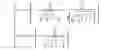
FIG. 2 is a schematic view of bunches of a fractured horizontal well of shale gas according to at least an embodiment of the present disclosure.
FIG. 3 is a schematic view of the induced stress field geometric distribution of a single fracture according to at least an embodiment of the present disclosure.
FIG. 4 is a schematic view of segmented single-bunch geometric distribution according to at least an embodiment of the present disclosure.
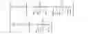
FIG. 5 is a schematic view of segmented multi-bunch geometric distribution according to at least an embodiment of the present disclosure, wherein in the figure is the overall schematic view of 4 segments and 3 bunches.
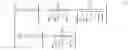
FIG. 6 is a schematic view of 3 bunches in a segment of multiple segments and multiple bunches according to at least an embodiment of the present disclosure.
FIG. 7 is the calculation results of induced stress difference according to at least an embodiment of the present disclosure.
DETAILED DESCRIPTION
The disclosure is further described in detail below with reference to the accompanying figures and embodiments. It can be understood that the specific embodiments described herein are only used to explain related content, rather than limiting the disclosure. It should also be noted that, only the parts related to the present disclosure are shown in the figures for the convenience of description.
It should be noted that the embodiments in the present disclosure and the features in the embodiments can be combined with each other without conflict. The disclosure will be described in detail below with reference to the figures and embodiments.
A method for optimizing bunch distance of fractured horizontal wells of shale gas should possess the following two features: 1. a geostress calculation model with appropriately considering existing fractures in formation after fracturing; 2. a set of stimulation method with appropriately calculating reservoir seepage conditions.
The present disclosure provides a method for optimizing bunch distance of fractured horizontal wells of shale gas.
As shown in FIG. 1, the method comprises the following steps:
S1: establishing a stress field distribution model for a single fracture, i.e. a mathematical model of horizontal induced stress generated by a single fracture at a point in the horizontal wellbore direction, including the induced stress in the minimum horizontal geostress direction of the fracture and the induced stress in the maximum horizontal geostress direction of the fracture;
S2: establishing an induced stress distribution model of multi-segment single-bunch fracturing for a horizontal well (when a horizontal well is fractured, multiple segments are fractured, and there is only a bunch per segment, which is called multi-segment single bunch);
S3: establishing an induced stress distribution model of multi-segment multi-bunch fracturing for a horizontal well, wherein taking the Nth-segment 3-bunch fracturing as an example, the three fractures of N1, N2 , and N3 at the perforated bunch of the Nth segment extend synchronously during fracturing, and since the three fractures of N1, N2 , and N3 are not formed in sequence, there are stress barrier and stress interference effects among the three fractures of the Nth fracturing segment;
S4: calculating the induced stress outside a fracture in a segment adjacent to previous fractured segment;
S5: calculating the induced stress between fractures inside a segment;
S6: calculating the induced stress outside a fracture in a segment adjacent to next fractured segment;
S7: calculating the horizontal induced stress difference of segmented multi-bunch fracturing for a horizontal well;
S8: according to the induced stress difference, determining the optimal bunch distance.
The following description will be made in conjunction with specific embodiments.
FIG. 2 shows a schematic view of shale gas fracturing horizontal well technique. In the figure, the horizontal well has 4 horizontal segments numbered sequentially 1-4 from left to right, and each segment has 3 bunches of fractures.
Step 1: establishing a stress field distribution model for a single fracture.
The geometrical distribution model of the induced stress field of a single fracture after shale gas fracturing is shown in FIG. 3. It is assumed that the cross section of the fracture is elliptical, the direction of the horizontal wellbore is the x-axis (the minimum horizontal geostress direction), and the direction of the fracture height is the z-axis (the direction perpendicular to the geostress direction). According to the theory of elastic mechanics, the model of horizontal induced stress generated a single fracture to a point on the x-axis at the position of a away from the fracture center is
{ σ h = p n ( 1 - a 2 r ( a 2 r ) 2 + 1 4 + a 2 r 4 ( ( a 2 r ) 2 + 1 4 ) 3 ) σ H = 2 p n v ( 1 - a 2 h ( a 2 r ) 2 + 1 4 ) ( 1 )
where σh is the induced stress in the minimum horizontal geostress direction of a fracture, MPa; σH is the induced stress in the maximum horizontal geostress direction of a fracture, MPa; pn is original net pressure in fractures, MPa; a is the distance from the fracture center to a measuring point, m; r is fracture half length, m; v is rock Poisson ratio.
Step 2: establishing an induced stress distribution model of multi-segment single-bunch fracturing for a horizontal well. When a horizontal well is fractured, multiple segments (N segments) are fractured and there is only a bunch per segment, which is called multi-segment single bunch). FIG. 4 shows a schematic view of a single bunch in 1, 2, 3 segments (only 3 segments are shown), i.e., only one bunch per segment.
However, the actual net pressure in the fracture of the Nth fractured segment, i.e., the effective net pressure is not the original net pressure, but the original net pressure minus the induced stress in the minimum horizontal geostress direction generated by the fractures of the previous N−1 segments at the position of the fracture of the segment, i.e., the expression of the effective net pressure is
p e n ( N ) = p n - ∑ i = 1 N - 1 σ h i ( N ) ( 2 )
where pen(N) is the effective net pressure in the fracture of the Nth segment, MPa; pn is the original pressure in the fracture of the Nth segment, MPa; σhi(N) is the induced stress in the minimum horizontal geostress direction generated by the fracturing of the ith segment in the fracture of the Nth segment, MPa.
At this point, the horizontal induced stress in the formation around the fracture of the Nth segment is obtained as
{ σ h N = p en ( N ) ( 1 - a 2 r ( a 2 r ) 2 + 1 4 + a 2 r 4 ( ( a 2 r ) 2 + 1 4 ) 3 ) σ H N = 2 p en ( N ) v ( 1 - a 2 r ( a 2 r ) 2 + 1 4 ) ( 3 )
where σhN is the induced stress in the minimum horizontal geostress direction generated by the fracturing of the Nth segment to the formation around the Nth segment, MPa; σHN is the induced stress in the maximum horizontal geostress direction generated by the fracturing of the Nth segment to the formation around the Nth segment, MPa.
pn in equation (1) is for a single fracture, that is, the initial condition is that only a fracture is fractured in the reservoir, and the original net pressure is also the effective net pressure. pen(N) in equation (3) is the effective net pressure in the fracture of the Nth segment of segmented single-bunch fracture.
After the fracturing of the Nth segment, the total induced stress in the formation around the segment is obtained by superimposing the induced stresses generated by each segment fracture at the point:
{ σ h ′ = ∑ i = 1 N σ h i σ H ′ = ∑ i = 1 N σ H i ( 4 )
where σ′h is the induced stress in the formation around the segment in the minimum horizontal geostress direction after the fracturing of the Nth segment, MPa; σ′H is the induced stress in the formation around the segment in the maximum horizontal geostress direction after the fracturing of the Nth segment, MPa; σhi is the induced stress in the minimum horizontal geostress direction generated by the fracturing of the ith segment to the point, MPa; σHi is the induced stress in the maximum horizontal geostress direction generated by the fracturing of the ith segment to the point, MPa.
Step 3: establishing an induced stress distribution model of multi-segment multi-bunch fracturing for a horizontal well.
Taking the fracturing of the Nth segment as an example, the three fractures of N1, N2, and N3 at the perforated bunch of the Nth segment extend synchronously during fracturing. Since the three fractures of N1, N2, and N3 are not formed in sequence, at this moment, there are stress barrier and stress interference effects among the three fractures in the Nth fracturing segment. The morphology of multi-segment multi-bunch fracturing is shown in FIG. 5.
The effective net pressure of Fracture N1 relative to the left formation is:
penl(N1)=pn−σh(N−1)3(N1) (5)
where penl(N1) is the effective net pressure of Fracture N1 relative to the left-side formation thereof, MPa; αh(N−1)3(N1) is the induced stress in the minimum horizontal geostress direction generated by the fracture at the third perforated bunch (here take the example of 3 bunches per segment) of the (N−1)th fractured segment to Fracture N1, MPa.
When the horizontal well fracturing generates fractures, the fractures start fracturing along the direction perpendicular to the direction of the minimum stress and extend along the direction of the maximum major stress. After the distance between segments is fixed, the middle position between two segments is selected as the original point, the x-axis is the direction of the minimum horizontal major stress, the y-axis is the direction of the maximum horizontal major stress, and the cross section through the axis of the horizontal wellbore is selected. In a two-dimensional coordinate system, for the fractures of the ith segment, the induced stress generated at any point of this coordinate between Fracture N1 and N2 is
{ σ enh ( N 1 , N 2 ) = P n sin β n 1 2 ( 2 l n 1 r n 2 ) 3 2 - P n [ r n 1 cos β n 1 ( r n 1 r n 2 ) 1 2 - 1 ] σ enH ( N 1 , N 2 ) = 2 v P n [ r n 1 cos β n 1 ( r n 1 r n 2 ) 1 2 - 1 ] ( 6 )
where σenh(N1, N2) is the induced stress in the minimum horizontal geostress direction generated by Fracture N1 to Fracture N2 , MPa; βn1 is the angle of Fracture N1 to a point in the right-side formation thereof; ln1 is the total length of Fracture N1, m; rn1 is the half length of Fracture N1, m; rn2 is the half length of Fracture N2m; σenH(N1, N2) is the induced stress in the maximum horizontal geostress direction generated by Fracture N1 to Fracture N2, MPa.
Likewise, the induced stress generated at any point of this coordinate between Fracture N2 and N3 can be obtained as
{ σ enh ( N 2 , N 3 ) = P n sin β n 2 2 ( 2 l n 2 r n 3 ) 3 2 - P n [ r n 2 cos β n 2 ( r n 2 r n 3 ) 1 2 - 1 ] σ enH ( N 2 , N 3 ) = 2 v P n [ r n 2 cos β n 2 ( r n 2 r n 3 ) 1 2 - 1 ] ( 7 )
where σenh(N2, N3) is the induced stress in the minimum horizontal geostress direction generated by Fracture N2 to Fracture N3, MPa; βn2 is the angle of Fracture N2 to a point in the right-side formation thereof; ln2 is the total length of Fracture N2, m; rn2 is the half length of Fracture N2, m; rn3 is the half length of Fracture N3, m; σenH(N2, N3) the induced stress in the maximum horizontal geostress direction generated by Fracture N2 to Fracture N3, MPa.
The calculation model for calculating the effective net pressure of the third fracture N3 in the segment relative to the right-side formation thereof is
p e n r ( N 3 ) = p n - ∑ i = 1 N - 1 σ h i 3 ( N 3 ) ( 8 )
where penr(N3) is the effective net pressure of Fracture N3 relative to the right-side formation thereof, MPa.
Step 4: calculating the induced stress outside a fracture in a segment adjacent to previous fractured segment (Point A in FIG. 6). The calculation model is
{ σ h N 1 = ∑ j = 1 N - 1 σ h i + σ h N 1 [ P e n l ( N 1 ) ] σ H N 1 = ∑ i = 1 N - 1 σ H i + σ H N 1 [ P e n l ( N 1 ) ] ( 9 )
where σhN1 is the total induced stress in the minimum horizontal geostress direction at the point, MPa; σHN1 is the total induced stress in the maximum horizontal geostress direction at the point, MPa; σhi is the induced stress in the minimum horizontal geostress direction generated by the fracturing of the ith segment to the point, MPa; σHl is the induced stress in the maximum horizontal geostress direction generated by the fracturing of the ith segment to the point, MPa; σhN1[penl(N1)] is the induced stress in the minimum horizontal geostress direction generated by the fracture at the first perforated bunch in the Nth segment to the left-side formation thereof, MPa; σhN1[penl(N1)] is the induced stress in the maximum horizontal geostress direction generated by the fracture at the first perforated bunch in the Nth segment to the left-side formation thereof, MPa.
The two parameters above can be obtained according to equation (3).
Step 5: calculating the induced stress between fractures inside a segment (Point B in FIG. 6). The calculation model is
{ σ h 1 = ∑ i = 1 N - 1 σ h i 1 + σ e n h ( N 1 , N 2 ) σ H 1 = ∑ i = 1 N - 1 σ H i1 + σ e n H ( N 1 , N 2 ) ( 10 )
where σh1 is the induced stress in the minimum horizontal geostress direction generated between Fracture N1 and N2, MPa; σhi1 is the induced stress in the minimum horizontal geostress direction generated by the fracture at the first perforated bunch in the ith fractured segment to the point, MPa; σH1 the induced stress in the maximum horizontal geostress direction generated between Fracture N1 and N2 , MPa; σHi1 is the induced stress in the maximum horizontal geostress direction generated by the fracture at the first perforated bunch of the ith fractured segment to the point, MPa.
The calculation model for calculating the induced stress between fractures inside a segment (Point C in FIG. 6) is
{ σ h 2 = ∑ i = 1 N - 1 σ h i 1 + σ e n h ( N 1 , N 2 ) + σ e n h ( N 2 , N 3 ) σ H 2 = ∑ i = 1 N - 1 σ H i1 + σ e n H ( N 1 , N 2 ) + σ e n H ( N 2 , N 3 ) ( 11 )
where σh2 is the induced stress in the minimum horizontal geostress direction generated between Fracture N2 and N3, MPa; σH2 is the induced stress in the maximum horizontal geostress direction generated between Fracture N2 and N3, MPa.
S6: calculating the induced stress outside a fracture in a segment adjacent to next fractured segment (Point D in FIG. 6). The calculation model is
{ σ h N 3 = ∑ i = 1 N - 1 σ h i + σ h N 3 [ p e n r ( N 3 ) ] σ H N 3 = ∑ i = 1 N - 1 σ H i + σ H N 3 [ p e n r ( N 3 ) ] ( 12 )
where σhN3 is the total induced stress in the minimum horizontal geostress direction at the point, MPa; σHN3 is the total induced stress in the maximum horizontal geostress direction at the point, MPa.
Although the embodiment takes three fractures as an example, the method provided by the present disclosure can be similarly applied to conditions of any fractures, and the repetitious details are not given here.
Step 7: calculating the horizontal induced stress difference of segmented multi-bunch fracturing for a horizontal well, wherein the position with the maximum induced stress difference among bunches is the optimal fracture distance. The calculation model is
σH=σHN1+σH1+σH2+σHN3 (13)
σh=σhN1+σh1+σh2+πhN3 (14)
Δσ=σH−σh (15)
where σh is the induced stress in the minimum horizontal geostress direction generated by formation, MPa; σH the induced stress in the maximum horizontal geostress direction generated by formation, MPa.
Step 8: according to the induced stress difference, determining the optimal bunch distance. The position with the maximum induced stress difference is the optimal bunch distance. Related curves can be drawn according to the induced stress difference, and the optimal bunch distance can be identified based on the distance between peaks and valleys of the curves.
As shown in FIG. 7, in the design scheme, the segment length of the horizontal well is 1000 m, and five segments are fractured, i.e. the distance between the center of the segments is 200 m. Taking three bunches in a segment as an example, when the calculated fracture half height is 30 m, the original net pressure is 15 Mpa, and the rock Poisson's ratio is 0.25, the stress diagram obtained based on the optimization method at the present disclosure shows that the optimal bunch distance is that N1 is at 57 m, N2 is at 100 m, and N3 is at 142 m.
The above are preferred embodiments of the present disclosure. It should be noted that without departing from the principles of the present disclosure those skilled in the art can also make several improvements and embroideries, which should also be considered as the scope of the present disclosure.
Claims
What is claimed is:1. A method for optimizing bunch distance of fractured horizontal wells of shale gas, characterized in that, the method comprises
establishing a stress field distribution model for a single fracture;
establishing an induced stress distribution model of multi-segment single-bunch fracturing for a horizontal well;
establishing an induced stress distribution model of multi-segment multi-bunch fracturing for a horizontal well;
calculating the induced stress outside a fracture in a segment adjacent to previous fractured segment;
calculating the induced stress between fractures inside a segment;
calculating the induced stress outside a fracture in a segment adjacent to next fractured segment;
calculating the horizontal induced stress difference of segmented multi-bunch fracturing for a horizontal well; and
according to the induced stress difference, determining the optimal bunch distance.
2. The method according to claim 1, characterized in that, the stress field distribution model for a single fracture is
{ σ h = p n ( 1 - a 2 r ( a 2 r ) 2 + 1 4 + a 2 r 4 ( ( a 2 r ) 2 + 1 4 ) 3 ) σ H = 2 p n v ( 1 - a 2 r ( a 2 r ) 2 + 1 4 )
where σh is the induced stress in the minimum horizontal geostress direction of a fracture, MPa; σH is the induced stress in the maximum horizontal geostress direction of a fracture, MPa; pn is original net pressure in fractures, MPa; a is the distance from the fracture center to a measuring point, m; r is fracture half length, m; v is rock Poisson ratio.
3. The method according to claim 1, characterized in that, the induced stress distribution model of multi-segment single-bunch fracturing for a horizontal well comprises:
the actual net pressure inside the fracture of the Nth segment, i.e. effective net pressure
p n ( N ) = p n - ∑ i = 1 N - 1 σ h i ( N )
where pen(N) is the effective net pressure in the fracture of the Nth segment, MPa; pn is the original pressure in the fracture of the Nth segment, MPa; σhi(N) is the induced stress in the minimum horizontal geostress direction generated by the fracturing of the ith segment in the fracture of the Nth segment, MPa;
the horizontal induced stress in the formation around the fracture of the Nth segment is
{ σ h N = p en ( N ) ( 1 - a 2 r ( a 2 r ) 2 + 1 4 + a 2 r 4 ( ( a 2 r ) 2 + 1 4 ) 3 ) σ H N = 2 p en ( N ) v ( 1 - a 2 r ( a 2 r ) 2 + 1 4 )
where σhN is the induced stress in the minimum horizontal geostress direction generated by the fracturing of the Nth segment to the formation around the Nth segment, MPa; σHN is the induced stress in the maximum horizontal geostress direction generated by the fracturing of the N th segment to the formation around the Nth segment, MPa;
after the fracturing of the Nth segment, the total induced stress in the formation around the segment is
{ σ h ′ = ∑ j = 1 N σ h i σ H ′ = ∑ i = 1 N σ H i
where σ′h is the induced stress in the formation around the segment in the minimum horizontal geostress direction after the fracturing of the Nth segment, MPa; σ′H is the induced stress in the formation around the segment in the maximum horizontal geostress direction after the fracturing of the Nth segment, MPa; σhi is the induced stress in the minimum horizontal geostress direction generated by the fracturing of the ith segment, MPa; σhd Hi is the induced stress in the maximum horizontal geostress direction generated by the fracturing of the ith segment, MPa.
4. The method according to claim 1, characterized in that, the said establishing an induced stress distribution model of multi-segment multi-bunch fracturing for a horizontal well comprises
calculating the effective net pressure of the first fracture in the segment relative to previous fractured segment;
calculating the effective net pressure of each fracture in the segment relative to the left- and right-side formation thereof; and
calculating the effective net pressure of the last fracture in the segment relative to next fractured segment.
5. The method according to claim 4, characterized in that, the multiple bunches are three bunches per segment, wherein the three bunches of fractures of the Nth segment are sequentially recorded as fractures N1, N2, and N3, Fracture N1 is the fracture near the previous fractured segment, i.e. the (N−1)th fractured segment, Fracture N3 is the fracture the furthest away from the (N−1)th fractured segment, Fracture N2 is the fracture between fracture N1 and fracture N3.
6. The method according to claim 4, characterized in that, the said multi-segment is segments of natural numbers equal to or greater than 3.
7. The method according to claim 5, characterized in that, the effective net pressure of Fracture N1 relative to the previous fractured segment is
penl(N1)=pn−σh(N−1)3(N1)
where penl(N1) is the effective net pressure of Fracture N1 relative to the left-side formation thereof, MPa; σh(N−1)3 (N1) is the induced stress in the minimum horizontal geostress direction generated by the fracture at the third perforated bunch (here take the example of 3 bunches per segment) of the (N−1)th fractured segment to Fracture N1, MPa;
the induced stress generated at any point in this coordinate between Fracture N1 and N2 is
{ σ e n h ( N 1 , N 2 ) = P n sin β n 1 2 ( 2 l n 1 r n 2 ) 3 2 - P n [ r n 1 cos β n 1 ( r n 1 r n 2 ) 1 2 - 1 ] σ e n H ( N 1 , N 2 ) = 2 v P n [ r n 1 cos β n 1 ( r n 1 r n 2 ) 1 2 - 1 ]
where σenh(N1, N2) is the induced stress in the minimum horizontal geostress direction generated by Fracture N1 to Fracture N2, MPa; βn1 is the angle of Fracture N1 to a point in the right-side formation thereof; ln1 is the total length of Fracture N1, m; rn1 is the half length of Fracture N1, m; rn2 is the half length of Fracture N2, m; σenH(N1, N2) is the induced stress in the maximum horizontal geostress direction generated by Fracture N1 to Fracture N2, MPa;
the relationship between Fracture N2 and N3 is
{ σ e n h ( N 2 , N 3 ) = P n sin β n 2 2 ( 2 l n 2 r n 3 ) 3 2 - P n [ r n 2 cos β n 2 ( r n 2 r n 3 ) 1 2 - 1 ] σ enH ( N 2 , N 3 ) = 2 v P n [ r n 2 cos β n 2 ( r n 2 r n 3 ) 1 2 - 1 ]
where σenh(N2, N3) is the induced stress in the minimum horizontal geostress direction generated by Fracture N2 to Fracture N3, MPa; βn2 is the angle of Fracture N2 to a point in the right-side formation thereof; ln2 is the total length of Fracture N2, m; rn2 is the half length of Fracture N2, m; hn3 is the half length of Fracture N3, m; σenH(N2, N3) the induced stress in the maximum horizontal geostress direction generated by Fracture N2 to Fracture N3, MPa;
the effective net pressure of Fracture N3 relative to the next fractured segment is
p enr ( N 3 ) = p n - ∑ i = 1 N - 1 σ h i 3 ( N 3 )
where penr(N3) is the effective net pressure of Fracture N3 relative to the right-side formation thereof, MPa.
8. The method according to claim 7, characterized in that, the specific calculation of the induced stress outside a fracture in a segment adjacent to previous fractured segment is as follows:
the induced stress outside a fracture inside the Nth segment adjacent to the previous fractured segment is:
{ σ h N 1 = ∑ i = 1 N - 1 σ h i + σ h N 1 [ p enl ( N 1 ) ] σ H N 1 = ∑ i = 1 N - 1 σ H i + σ H N 1 [ p enl ( N 1 ) ]
where σhN1 is the total induced stress in the minimum horizontal geostress direction, MPa; σHN1 is the total induced stress in the maximum horizontal geostress direction, MPa; σhi is the induced stress in the minimum horizontal geostress direction generated by the fracturing of the ith segment, MPa; σHi is the induced stress in the maximum horizontal geostress direction generated by the fracturing of the ith segment, MPa; σhN1[Penl(N1)] is the induced stress in the minimum horizontal geostress direction generated by the fracture at the first perforated bunch of the Nth segment to the previous fractured segment, MPa; σhN1[penl(N1)] is the induced stress in the maximum horizontal geostress direction generated by the fracture at the first perforated bunch of the Nth segment to the previous fractured segment, MPa;
the induced stress between fractures of the Nth segment comprises the induced stress between Fracture N1 and N2
{ σ h 1 = ∑ i = 1 N - 1 σ h i 1 + σ e n h ( N 1 , N 2 ) σ H 1 = ∑ i = 1 N - 1 σ H i 1 + σ e n H ( N 1 , N 2 )
where σh1 is the induced stress in the minimum horizontal geostress direction generated between Fracture N1 and N2, MPa; σhi1 is the induced stress in the minimum horizontal geostress direction generated by the fracture at the first perforated bunch of the ith fractured segment, MPa; σH1 the induced stress in the maximum horizontal geostress direction generated between Fracture N1 and N2, MPa; σHi1 is the induced stress in the maximum horizontal geostress direction generated by the fracture at the first perforated bunch of the ith fractured segment, MPa;
the induced stress between Fracture N2 and N3 is
{ σ h 2 = ∑ j = 1 N - 1 σ h i 1 + σ e r ι h ( N 1 , N 2 ) + σ e n h ( N 2 , N 3 ) σ H 2 = ∑ j = 1 N - 1 σ H j 1 + σ e n H ( N 1 , N 2 ) + σ e n H ( N 2 , N 3 )
where σh2 is the induced stress in the minimum horizontal geostress direction generated between Fracture N2 and N3, MPa; σH2 is the induced stress in the maximum horizontal geostress direction generated between Fracture N2 and N3, MPa;
the induced stress outside a fracture in Nth segment adjacent to next fractured segment is
{ σ h N 3 = ∑ i = 1 N - 1 σ h i + σ h N 3 [ p e n r ( N 3 ) ] σ H N 3 = ∑ i = 1 N - 1 σ H i + σ H N 3 [ p e n r ( N 3 ) ]
where σhN3 is the total induced stress in the minimum horizontal geostress direction at the point, MPa; σHN3 is the total induced stress in the maximum horizontal geostress direction at the point, MPa.
9. The method according to claim 8, characterized in that, the horizontal induced stress difference Δσ of segmented multi-bunch fracturing for a horizontal well is
σH=σHN1+σH1+σH2+σHN3σh=σhN1+σh1+σh2+σhN3Δσ=σH−σh
where σh is the induced stress in the minimum horizontal geostress direction generated by formation, MPa; σH the induced stress in the maximum horizontal geostress direction generated by formation, MPa.
10. The method according to claim 9, characterized in that, the position with the maximum induced stress difference is the optimal bunch distance.
Images & Drawings included:


Sources:
- United States Patent and Trademark Office - verify current appl. status at the USPTO↗
Recent applications in this class:
- » 20240248234 2024-07-25
PROCESSES FOR PREDICTING AND ADDRESSING RETROGRADE CONDENSATE LIQUID DROPOUT IN A SUBSURFACE FORMATION - » 20240210591 2024-06-27
Characterization of Subsurface Geological Formations - » 20240192400 2024-06-13
GRIDLESS VOLUMETRIC COMPUTATION - » 20240176043 2024-05-30
METHODS AND SYSTEMS FOR AUTOMATIC WELL PLACEMENT PLANNING DURING RESERVOIR SIMULATION - » 20240142663 2024-05-02
EXPERIMENTAL DEVICE AND METHOD FOR SIMULATING SUBSURFACE EROSION PROCESS - » 20240134087 2024-04-25
BLAST HEAVE MODELING UTILIZING ENERGY PARTITIONING - » 20240125970 2024-04-18
METHOD AND MACHINE-READABLE MEDIUM FOR BUILDING 2D DEPOSITIONAL MODELS - » 20240111072 2024-04-04
Method and Apparatus for Petrophysical Classification, Characterization, and Uncertainty Estimation - » 20240094433 2024-03-21
INTEGRATED AUTONOMOUS OPERATIONS FOR INJECTION-PRODUCTION ANALYSIS AND PARAMETER SELECTION - » 20240094432 2024-03-21
Geological Neural Network Methodology (Geo-Net) For Reservoir Optimization And Assisted History Match
Recent applications for this Assignee:
- » 20250242341 2025-07-31
PREPARATION METHOD FOR ACTIVATED COKE CATALYST CAPABLE OF SIMULTANEOUSLY REMOVING NO, SO2 AND HCl - » 20250111521 2025-04-03
Method and system for analyzing global average grayscale change of tundish ink tracing experiment - » 20250075290 2025-03-06
MULTI-SOURCE SOLID WASTE RECYCLING METHOD BASED ON COMPOSITION DESIGN FOR CALCIUM-SILICON-ALUMINUM-MAGNESIUM OXIDE - » 20250011941 2025-01-09
CORROSION INHIBITOR OF PLATANUS ACERIFOLIA LEAF EXTRACT AND APPLICATION THEREOF - » 20240401237 2024-12-05
METHOD FOR PREPARING DIRECTIONALLY SOLIDIFIED TiAl ALLOY - » 20240401161 2024-12-05
Method for controlling nitrogen in steelmaking by spraying hydrogen containing plasma - » 20240367221 2024-11-07
Thin metal strip continuous casting method using momentum flow distribution - » 20240286143 2024-08-29
SYSTEM FOR GRADUALLY PULVERIZING AND DRYING WATER-CONTAINING MATERIALS - » 20240256829 2024-08-01
WIND POWER GENERATION QUANTILE PREDICTION METHOD BASED ON MACHINE MENTAL MODEL AND SELF-ATTENTION - » 20240253621 2024-08-01
Intervention-based shared control method and apparatus in forward collision avoidance scenario of autonomous vehicle