Liquid crystal display and method for driving same
US20200312254A1
2020-10-01
16/309,940
2017-12-26
✅ Patent granted
US 11,120,753 B2
2021-09-14
WO; PCT/CN2017/118577; 20171226
WO; WO2018/121519; 20180705
Julie Anne Watko
Kilpatrick Townsend & Stockton
2037-12-26
Abstract:
A liquid crystal display and a method for driving same, capable of eliminating large viewing angle color shift of a liquid crystal display having VA liquid crystals. The liquid crystal display comprises a liquid crystal panel (10) and a driving module (20). The driving module (20) is used for respectively providing different pixel voltages of the same polarity to each liquid crystal pixel (Pab) in the two adjacent frames to deflect liquid crystal molecules of the liquid crystal pixel (Pab), wherein in each of the two adjacent frames, the pixel voltage of each liquid crystal pixel (Pab) varies by using the average pixel voltage of liquid crystal pixels (Pab) in a pixel interval, in which the liquid crystal pixels (Pab) are spaced from the liquid crystal pixel (Pab) in a first direction, a second direction, a third direction, and a fourth direction by a plurality of pixels, as a parameter.
Assignee:
- HKC CORPORATION LIMITED 1,129 🇨🇳 Shenzhen, China
- Chongqing HKC Optoelectronics Technology Co., Ltd. 492 🇨🇳 Chongqing, China
Applicant:
Interested in similar patents?
Get notified when new applications in this technology area are published.
Classification:
G09G3/3426 » CPC main
Control arrangements or circuits, of interest only in connection with visual indicators other than cathode-ray tubes for presentation of an assembly of a number of characters, e.g. a page, by composing the assembly by combination of individual elements arranged in a matrix no fixed position being assigned to or needed to be assigned to the individual characters or partial characters by control of light from an independent source; Control of illumination source using several illumination sources separately controlled corresponding to different display panel areas, e.g. along one dimension such as lines the different display panel areas being distributed in two dimensions, e.g. matrix
G09G3/3614 » CPC further
Control arrangements or circuits, of interest only in connection with visual indicators other than cathode-ray tubes for presentation of an assembly of a number of characters, e.g. a page, by composing the assembly by combination of individual elements arranged in a matrix no fixed position being assigned to or needed to be assigned to the individual characters or partial characters by control of light from an independent source using liquid crystals; Control of matrices with row and column drivers Control of polarity reversal in general
G09G3/3666 » CPC further
Control arrangements or circuits, of interest only in connection with visual indicators other than cathode-ray tubes for presentation of an assembly of a number of characters, e.g. a page, by composing the assembly by combination of individual elements arranged in a matrix no fixed position being assigned to or needed to be assigned to the individual characters or partial characters by control of light from an independent source using liquid crystals; Control of matrices with row and column drivers using an active matrix with the matrix divided into sections
G09G2320/0233 » CPC further
Control of display operating conditions; Improving the quality of display appearance Improving the luminance or brightness uniformity across the screen
G09G2320/0242 » CPC further
Control of display operating conditions; Improving the quality of display appearance Compensation of deficiencies in the appearance of colours
G09G2320/0247 » CPC further
Control of display operating conditions; Improving the quality of display appearance Flicker reduction other than flicker reduction circuits used for single beam cathode-ray tubes
G02F1/13306 » CPC further
Devices or arrangements for the control of the intensity, colour, phase, polarisation or direction of light arriving from an independent light source, e.g. switching, gating or modulating; Non-linear optics for the control of the intensity, phase, polarisation or colour based on liquid crystals, e.g. single liquid crystal display cells; Constructional arrangements; Operation of liquid crystal cells; Circuit arrangements Circuit arrangements or driving methods for the control of single liquid crystal cells
G09G3/3607 » CPC main
Control arrangements or circuits, of interest only in connection with visual indicators other than cathode-ray tubes for presentation of an assembly of a number of characters, e.g. a page, by composing the assembly by combination of individual elements arranged in a matrix no fixed position being assigned to or needed to be assigned to the individual characters or partial characters by control of light from an independent source using liquid crystals for displaying colours or for displaying grey scales with a specific pixel layout, e.g. using sub-pixels
G02F1/13452 » CPC further
Devices or arrangements for the control of the intensity, colour, phase, polarisation or direction of light arriving from an independent light source, e.g. switching, gating or modulating; Non-linear optics for the control of the intensity, phase, polarisation or colour based on liquid crystals, e.g. single liquid crystal display cells; Constructional arrangements; Operation of liquid crystal cells; Circuit arrangements; Constructional arrangements; Manufacturing methods; Conductors connecting electrodes to cell terminals Conductors connecting driver circuitry and terminals of panels
G02F1/133308 » CPC further
Devices or arrangements for the control of the intensity, colour, phase, polarisation or direction of light arriving from an independent light source, e.g. switching, gating or modulating; Non-linear optics for the control of the intensity, phase, polarisation or colour based on liquid crystals, e.g. single liquid crystal display cells; Constructional arrangements; Operation of liquid crystal cells; Circuit arrangements; Constructional arrangements; Manufacturing methods Support structures for LCD panels, e.g. frames or bezels
G02F1/133753 » CPC further
Devices or arrangements for the control of the intensity, colour, phase, polarisation or direction of light arriving from an independent light source, e.g. switching, gating or modulating; Non-linear optics for the control of the intensity, phase, polarisation or colour based on liquid crystals, e.g. single liquid crystal display cells; Constructional arrangements; Operation of liquid crystal cells; Circuit arrangements; Constructional arrangements; Manufacturing methods; Surface-induced orientation of the liquid crystal molecules, e.g. by alignment layers with different alignment orientations or pretilt angles on a same surface, e.g. for grey scale or improved viewing angle
G02F1/136286 » CPC further
Devices or arrangements for the control of the intensity, colour, phase, polarisation or direction of light arriving from an independent light source, e.g. switching, gating or modulating; Non-linear optics for the control of the intensity, phase, polarisation or colour based on liquid crystals, e.g. single liquid crystal display cells; Constructional arrangements; Operation of liquid crystal cells; Circuit arrangements; Liquid crystal cells structurally associated with a semi-conducting layer or substrate, e.g. cells forming part of an integrated circuit; Active matrix addressed cells Wiring, e.g. gate line, drain line
G09G3/3406 » CPC further
Control arrangements or circuits, of interest only in connection with visual indicators other than cathode-ray tubes for presentation of an assembly of a number of characters, e.g. a page, by composing the assembly by combination of individual elements arranged in a matrix no fixed position being assigned to or needed to be assigned to the individual characters or partial characters by control of light from an independent source Control of illumination source
G09G3/367 » CPC further
Control arrangements or circuits, of interest only in connection with visual indicators other than cathode-ray tubes for presentation of an assembly of a number of characters, e.g. a page, by composing the assembly by combination of individual elements arranged in a matrix no fixed position being assigned to or needed to be assigned to the individual characters or partial characters by control of light from an independent source using liquid crystals; Control of matrices with row and column drivers with a nonlinear element in series with the liquid crystal cell, e.g. a diode, or M.I.M. element
G09G3/3611 » CPC further
Control arrangements or circuits, of interest only in connection with visual indicators other than cathode-ray tubes for presentation of an assembly of a number of characters, e.g. a page, by composing the assembly by combination of individual elements arranged in a matrix no fixed position being assigned to or needed to be assigned to the individual characters or partial characters by control of light from an independent source using liquid crystals Control of matrices with row and column drivers
G09G3/3648 » CPC further
Control arrangements or circuits, of interest only in connection with visual indicators other than cathode-ray tubes for presentation of an assembly of a number of characters, e.g. a page, by composing the assembly by combination of individual elements arranged in a matrix no fixed position being assigned to or needed to be assigned to the individual characters or partial characters by control of light from an independent source using liquid crystals; Control of matrices with row and column drivers using an active matrix
G09G3/3677 » CPC further
Control arrangements or circuits, of interest only in connection with visual indicators other than cathode-ray tubes for presentation of an assembly of a number of characters, e.g. a page, by composing the assembly by combination of individual elements arranged in a matrix no fixed position being assigned to or needed to be assigned to the individual characters or partial characters by control of light from an independent source using liquid crystals; Control of matrices with row and column drivers; Details of drivers for scan electrodes suitable for active matrices only
G02F1/1335 IPC
Devices or arrangements for the control of the intensity, colour, phase, polarisation or direction of light arriving from an independent light source, e.g. switching, gating or modulating; Non-linear optics for the control of the intensity, phase, polarisation or colour based on liquid crystals, e.g. single liquid crystal display cells; Constructional arrangements; Operation of liquid crystal cells; Circuit arrangements; Constructional arrangements; Manufacturing methods Structural association of cells with optical devices, e.g. polarisers or reflectors
G02F2201/52 » CPC further
Constructional arrangements not provided for in groups - RGB geometrical arrangements
G09G3/3644 » CPC further
Control arrangements or circuits, of interest only in connection with visual indicators other than cathode-ray tubes for presentation of an assembly of a number of characters, e.g. a page, by composing the assembly by combination of individual elements arranged in a matrix no fixed position being assigned to or needed to be assigned to the individual characters or partial characters by control of light from an independent source using liquid crystals; Control of matrices with row and column drivers using a passive matrix with the matrix divided into sections
G09G2310/0254 » CPC further
Command of the display device; Addressing, scanning or driving the display screen or processing steps related thereto; Details of the generation of driving signals Control of polarity reversal in general, other than for liquid crystal displays
G09G2320/0285 » CPC further
Control of display operating conditions; Improving the quality of display appearance using tables for spatial correction of display data
G09G2320/062 » CPC further
Control of display operating conditions; Adjustment of display parameters; The adjustment depending on the type of the information to be displayed Adjustment of illumination source parameters
G09G2320/068 » CPC further
Control of display operating conditions; Adjustment of display parameters for control of viewing angle adjustment
G09G2320/0626 » CPC further
Control of display operating conditions; Adjustment of display parameters for control of overall brightness
G09G2320/0646 » CPC further
Control of display operating conditions; Adjustment of display parameters for control of overall brightness Modulation of illumination source brightness and image signal correlated to each other
G09G2320/0653 » CPC further
Control of display operating conditions; Adjustment of display parameters for control of overall brightness Controlling or limiting the speed of brightness adjustment of the illumination source
G09G2320/0666 » CPC further
Control of display operating conditions; Adjustment of display parameters for control of colour parameters, e.g. colour temperature
G09G2320/0686 » CPC further
Control of display operating conditions; Adjustment of display parameters with two or more screen areas displaying information with different brightness or colours
G09G2340/16 » CPC further
Aspects of display data processing Determination of a pixel data signal depending on the signal applied in the previous frame
G09G3/36 IPC
Control arrangements or circuits, of interest only in connection with visual indicators other than cathode-ray tubes for presentation of an assembly of a number of characters, e.g. a page, by composing the assembly by combination of individual elements arranged in a matrix no fixed position being assigned to or needed to be assigned to the individual characters or partial characters by control of light from an independent source using liquid crystals
G09G3/34 IPC
Control arrangements or circuits, of interest only in connection with visual indicators other than cathode-ray tubes for presentation of an assembly of a number of characters, e.g. a page, by composing the assembly by combination of individual elements arranged in a matrix no fixed position being assigned to or needed to be assigned to the individual characters or partial characters by control of light from an independent source
G02F1/1337 IPC
Devices or arrangements for the control of the intensity, colour, phase, polarisation or direction of light arriving from an independent light source, e.g. switching, gating or modulating; Non-linear optics for the control of the intensity, phase, polarisation or colour based on liquid crystals, e.g. single liquid crystal display cells; Constructional arrangements; Operation of liquid crystal cells; Circuit arrangements; Constructional arrangements; Manufacturing methods Surface-induced orientation of the liquid crystal molecules, e.g. by alignment layers
G02F1/1345 IPC
Devices or arrangements for the control of the intensity, colour, phase, polarisation or direction of light arriving from an independent light source, e.g. switching, gating or modulating; Non-linear optics for the control of the intensity, phase, polarisation or colour based on liquid crystals, e.g. single liquid crystal display cells; Constructional arrangements; Operation of liquid crystal cells; Circuit arrangements; Constructional arrangements; Manufacturing methods Conductors connecting electrodes to cell terminals
G02F1/1362 » CPC further
Devices or arrangements for the control of the intensity, colour, phase, polarisation or direction of light arriving from an independent light source, e.g. switching, gating or modulating; Non-linear optics for the control of the intensity, phase, polarisation or colour based on liquid crystals, e.g. single liquid crystal display cells; Constructional arrangements; Operation of liquid crystal cells; Circuit arrangements; Liquid crystal cells structurally associated with a semi-conducting layer or substrate, e.g. cells forming part of an integrated circuit Active matrix addressed cells
G02F1/133 IPC
Devices or arrangements for the control of the intensity, colour, phase, polarisation or direction of light arriving from an independent light source, e.g. switching, gating or modulating; Non-linear optics for the control of the intensity, phase, polarisation or colour based on liquid crystals, e.g. single liquid crystal display cells Constructional arrangements; Operation of liquid crystal cells; Circuit arrangements
G02F1/1333 IPC
Devices or arrangements for the control of the intensity, colour, phase, polarisation or direction of light arriving from an independent light source, e.g. switching, gating or modulating; Non-linear optics for the control of the intensity, phase, polarisation or colour based on liquid crystals, e.g. single liquid crystal display cells; Constructional arrangements; Operation of liquid crystal cells; Circuit arrangements Constructional arrangements; Manufacturing methods
G02F1/1368 » CPC further
Devices or arrangements for the control of the intensity, colour, phase, polarisation or direction of light arriving from an independent light source, e.g. switching, gating or modulating; Non-linear optics for the control of the intensity, phase, polarisation or colour based on liquid crystals, e.g. single liquid crystal display cells; Constructional arrangements; Operation of liquid crystal cells; Circuit arrangements; Liquid crystal cells structurally associated with a semi-conducting layer or substrate, e.g. cells forming part of an integrated circuit; Active matrix addressed cells in which the switching element is a three-electrode device
G09G2320/0261 » CPC further
Control of display operating conditions; Improving the quality of display appearance in the context of movement of objects on the screen or movement of the observer relative to the screen
Description
FILED
The present disclosure relates to the field of display technologies, in particular, to a liquid crystal display and method for driving same.
BACKGROUND
With the evolution of optoelectronics and semiconductor technologies, Flat Panel Displays have thereby a booming development as well. Among various Flat Panel Displays, Liquid Crystal Displays (LCD) have been applied in various aspects of production and daily life due to a number of advantageous characteristics such as high space utilization efficiency, low power consumption, no radiation, low electromagnetic interference and the like. A liquid crystal display typically includes a liquid crystal panel, a backlight module and a driving module driving the liquid crystal panel and the backlight module, wherein the liquid crystal panel includes a color filter substrate (i.e. CF substrate) and an array substrate which are configured by cell-aligning, and liquid crystals interposed therebetween. Among the existing large dimensioned liquid crystal panels, negative-type VA (Vertically Aligned) liquid crystals are mostly adopted. However, negative-type VA liquid crystals have many deficiencies. Particularly, color shift phenomenon may occur as a liquid crystal panel using negative-type VA type liquid crystals is viewed at a large viewing angle, when desired to present the liquid crystal panel at a large viewing angle.
To overcome the deficiencies as described above, it tends to further divide respective sub pixels into Main/Sub secondary pixels, and provide different pixel voltages to the Main/Sub secondary pixels. However, such pixel design often requires for adding metal wires and thin-film transistors (TFT) to drive the Main/Sub secondary pixels, which causes the sacrifice of the aperture ratio, resulting in the reduction of transmittance. In order to maintain the original transmittance, it is necessary to increase the luminance of the light emitted by the backlight module, thereby directly increasing the cost of the backlight module.
SUMMARY
To solve the problem described above, the present disclosure provides a liquid crystal display and a driving method thereof that solve low color shift without affecting aperture ratio.
The present disclosure provides a liquid crystal display, which includes: a liquid crystal panel, including a plurality of liquid crystal pixels arranged in array and configured to display the same image in two adjacent frames; a driving module, configured to respectively provide different pixel voltages of the same polarity for each of the liquid crystal pixels in two adjacent frames, so as to deflect liquid crystal molecules of each of the liquid crystal pixels, wherein the pixel voltage of each liquid crystal pixel in each of the two adjacent frames changes with an average pixel voltage of each of the liquid crystal pixels in a pixel interval as a parameter, from which the liquid crystal pixel is spaced respectively by a plurality of pixel distances along a first direction, a second direction, a third direction and a fourth direction.
Further, the liquid crystal display also includes a backlight module, wherein the liquid crystal panel is divided into M×N rectangular panel partitions, the backlight module is divided into M×N rectangular backlight partitions, 1≤i≤M, 1≤j≤N, and the rectangular panel partition of the i-th row and the j-th column corresponds to the rectangular backlight partition of the i-th row and the j-th column. In each of the two adjacent frames, after the liquid crystal molecules of each liquid crystal pixel in each of the rectangular panel partitions are deflected, the driving module is further configured to drive all of the rectangular backlight partitions to emit light at the same time, or in each of the two adjacent frames, after the liquid crystal molecules of each liquid crystal pixel in the rectangular panel partition of the i-th row and the j-th column are deflected, the driving module is further configured to drive the rectangular backlight partition of the i-th row and the j-th column to emit light, until all of the rectangular backlight partitions are driven to emit light.
Further, the sum of the pixel voltages of the liquid crystal pixels in the rectangular panel partition of the i-th row and j-th column and a luminance of the rectangular backlight partition of the i-th row and j-th column satisfy the following formula 1,
Lij_1*Vij_1=Lij_2*Vij_2 [Formula 1]
wherein Lij_1 denotes the luminance of the rectangular backlight partition of the i-th row and the j-th column in the previous frame of two adjacent frames, Vij_1 denotes the sum of the pixel voltages of the liquid crystal pixels in the rectangular panel partition of the i-th row and the j-th column in the previous frame of the two adjacent frames, Lij_2 denotes the luminance of the rectangular backlight partition of the i-th row and the j-th column in the subsequent frame of two adjacent frames, Vij_2 denotes the sum of the pixel voltages of the liquid crystal pixels in the rectangular panel partition of the i-th row and the j-th column in the subsequent frame of the two adjacent frames.
Further, the sum of the pixel voltages of the liquid crystal pixels in the rectangular panel partition of the i-th row and j-th column and the luminance of the rectangular backlight partition of the i-th row and j-th column satisfy the following formula 2,
Lij_1*Vij_1+Lij_2*Vij_2=2*Lij*Vij [Formula 2]
wherein Lij denotes the luminance of the rectangular backlight partition of the i-th row and j-th column when the liquid crystal display is configured to display the image only in one frame, Vij denotes the sum of the pixel voltages of the liquid crystal pixels in the rectangular panel partition when the liquid crystal display is configured to display the image only in one frame, Lij_1 denotes the luminance of the rectangular backlight partition of the i-th row and the j-th column in the previous frame of two adjacent frames, Vij_1 denotes the sum of the pixel voltages of the liquid crystal pixels in the rectangular panel partition of the i-th row and the j-th column in the previous frame of the two adjacent frames, Lij_2 denotes the luminance of the rectangular backlight partition of the i-th row and the j-th column in the subsequent frame of two adjacent frames, Vij_2 denotes the sum of the pixel voltages of the liquid crystal pixels in the rectangular panel partition of the i-th row and the j-th column in the subsequent frame of the two adjacent frames.
The present disclosure further provides a driving method for a liquid crystal display that includes a liquid crystal panel including a plurality of liquid crystal pixels arranged in array, and a driving module, and the liquid crystal panel is configured to display the same image in two adjacent frames,
wherein the driving method for the liquid crystal display includes:
providing, by a driving module, a pixel voltage to each of the liquid crystal pixels in a previous frame of the two adjacent frames, so as to deflect liquid crystal molecules of each of the liquid crystal pixels,
providing, by the driving module, a pixel voltage to each of the liquid crystal pixels in a subsequent frame of the two adjacent frames, so as to deflect liquid crystal molecules of each of the liquid crystal pixels,
wherein the pixel voltage of each liquid crystal pixel changes with an average pixel voltage of each of the liquid crystal pixels in a pixel interval as a parameter, from which the liquid crystal pixel is spaced respectively by a plurality of pixel distances along a first direction, a second direction, a third direction and a fourth direction, and the pixel voltages of the same liquid crystal pixel in the previous frame and in the subsequent frame have the same polarity but are different in values.
Further, the liquid crystal display also includes a backlight module, wherein the liquid crystal panel is divided into M×N rectangular panel partitions, the backlight module is divided into M×N rectangular backlight partitions, 1≤i≤M, 1≤j≤N, and the rectangular panel partition of the i-th row and the j-th column corresponds to the rectangular backlight partition of the i-th row and the j-th column.
The driving method for the liquid crystal display further includes:
in the previous frame of the two adjacent frames, after the liquid crystal molecules of each liquid crystal pixel in each of the rectangular panel partitions are deflected, driving, by the driving module, all of the rectangular backlight partitions to emit light at the same time, and
in the subsequent frame of the two adjacent frames, after the liquid crystal molecules of each liquid crystal pixel in each of the rectangular panel partitions are deflected, driving, by the driving module, all of the rectangular backlight partitions to emit light at the same time.
Alternatively, the driving method for the liquid crystal display further includes:
in the previous frame of the two adjacent frames, after the liquid crystal molecules of each liquid crystal pixel in the rectangular panel partition of the i-th row and j-th column are deflected, driving, by the driving module, the rectangular backlight partition of the i-th row and j-th column to emit light, until all of the rectangular backlight partitions are driven to emit light, and
in the subsequent frame of the two adjacent frames, after the liquid crystal molecules of each liquid crystal pixel in the rectangular panel partition of the i-th row and j-th column are deflected, driving, by the driving module, the rectangular backlight partition of the i-th row and j-th column to emit light, until all of the rectangular backlight partitions are driven to emit light.
Further, the sum of the pixel voltages of the liquid crystal pixels in the rectangular panel partition of the i-th row and j-th column and the luminance of the rectangular backlight partition of the i-th row and j-th column satisfy the formula 1 and/or the formula 2 as following according to the driving method for the liquid crystal display described above,
Lij_1*Vij_1=Lij_2*Vij_2 [Formula 1]
Lij_1*Vij_1+Lij_2*Vij_2=2*Lij*Vij [Formula 2]
wherein, Lij_1 denotes the luminance of the rectangular backlight partition of the i-th row and the j-th column in the previous frame of two adjacent frames, Vij_1 denotes the sum of the pixel voltages of the liquid crystal pixels in the rectangular panel partition of the i-th row and the j-th column in the previous frame of the two adjacent frames, Lij_2 denotes the luminance of the rectangular backlight partition of the i-th row and the j-th column in the subsequent frame of two adjacent frames, Vij_2 denotes the sum of the pixel voltages of the liquid crystal pixels in the rectangular panel partition of the i-th row and the j-th column in the subsequent frame of the two adjacent frames, Lij denotes the luminance of the rectangular backlight partition of the i-th row and j-th column when the liquid crystal display is configured to display the image only in one frame, and Vij denotes the sum of the pixel voltages of the liquid crystal pixels in the rectangular panel partition when the liquid crystal display is configured to display the image only in one frame.
The present disclosure provides a liquid crystal display, including: a liquid crystal panel including a plurality of liquid crystal pixels and configured to display the same image in two adjacent frames. The liquid crystal display further includes a backlight module wherein the liquid crystal panel is divided into M×N rectangular panel partitions, the backlight module is divided into M×N rectangular backlight partitions, 1≤i≤M, 1≤j≤N, and the rectangular panel partition of the i-th row and the j-th column corresponds to the rectangular backlight partition of the i-th row and the j-th column; and a driving module, configured to respectively provide different pixel voltages of the same polarity for each of the liquid crystal pixels in two adjacent frames, so as to deflect liquid crystal molecules of each of the liquid crystal pixels. After the liquid crystal molecules of each liquid crystal pixel in each of the rectangular panel partitions are deflected, the driving module is further configured to drive all of the rectangular backlight partitions to emit light at the same time, wherein in each of the two adjacent frames the pixel voltage of each liquid crystal pixel changes with an average pixel voltage of each of the liquid crystal pixels in a pixel interval as a parameter, from which the liquid crystal pixel is spaced respectively by a plurality of pixel distances along a first direction, a second direction, a third direction and a fourth direction.
Further, the sum of the pixel voltages of the liquid crystal pixels in the rectangular panel partition of the i-th row and j-th column and the luminance of the rectangular backlight partition of the i-th row and j-th column satisfy the following formula 1,
Lij_1*Vij_1=Lij_2*Vij_2 [Formula 1]
wherein Lij_1 denotes the luminance of the rectangular backlight partition of the i-th row and the j-th column in the previous frame of two adjacent frames, Vij_1 denotes the sum of the pixel voltages of the liquid crystal pixels in the rectangular panel partition of the i-th row and the j-th column in the previous frame of the two adjacent frames, Lij_2 denotes the luminance of the rectangular backlight partition of the i-th row and the j-th column in the subsequent frame of two adjacent frames, Vij_2 denotes the sum of the pixel voltages of the liquid crystal pixels in the rectangular panel partition of the i-th row and the j-th column in the subsequent frame of the two adjacent frames.
Further, the sum of the pixel voltages of the liquid crystal pixels in the rectangular panel partition of the i-th row and j-th column and the luminance of the rectangular backlight partition of the i-th row and j-th column satisfy the following formula 2,
Lij_1*Vij_1+Lij_2*Vij_2=2*Lij*Vij [Formula 2]
wherein Lij denotes the luminance of the rectangular backlight partition of the i-th row and j-th column when the liquid crystal display is configured to display the image only in one frame, Vij denotes the sum of the pixel voltages of the liquid crystal pixels in the rectangular panel partition when the liquid crystal display is configured to display the image only in one frame, Lij_1 denotes the luminance of the rectangular backlight partition of the i-th row and the j-th column in the previous frame of two adjacent frames, Vij_1 denotes the sum of the pixel voltages of the liquid crystal pixels in the rectangular panel partition of the i-th row and the j-th column in the previous frame of the two adjacent frames, Lij_2 denotes the luminance of the rectangular backlight partition of the i-th row and the j-th column in the subsequent frame of two adjacent frames, Vij_2 denotes the sum of the pixel voltages of the liquid crystal pixels in the rectangular panel partition of the i-th row and the j-th column in the subsequent frame of the two adjacent frames.
Further, the sum of the pixel voltages of the liquid crystal pixels in the rectangular panel partition of the i-th row and j-th column and the luminance of the rectangular backlight partition of the i-th row and j-th column satisfy the following formula 2,
Lij_1*Vij_1+Lij_2*Vij_2=2*Lij*Vij [Formula 2]
wherein Lij denotes the luminance of the rectangular backlight partition of the i-th row and j-th column when the liquid crystal display is configured to display the image only in one frame, and Vij denotes the sum of the pixel voltages of the liquid crystal pixels in the rectangular panel partition when the liquid crystal display is configured to display the image only in one frame.
Further, the sum of the pixel voltages of the liquid crystal pixels in the rectangular panel partition of the i-th row and j-th column and the luminance of the rectangular backlight partition of the i-th row and j-th column satisfy the formula 1 and or the formula 2 as following,
Lij_1*Vij_1=Lij_2*Vij_2 [Formula 1]
Lij_1*Vij_1+Lij_2*Vij_2=2*Lij*Vij [Formula 2]
wherein Lij_1 denotes the luminance of the rectangular backlight partition of the i-th row and the j-th column in the previous frame of two adjacent frames, Vij_1 denotes the sum of the pixel voltages of the liquid crystal pixels in the rectangular panel partition of the i-th row and the j-th column in the previous frame of the two adjacent frames, Lij_2 denotes the luminance of the rectangular backlight partition of the i-th row and the j-th column in the subsequent frame of two adjacent frames, Vij_2 denotes the sum of the pixel voltages of the liquid crystal pixels in the rectangular panel partition of the i-th row and the j-th column in the subsequent frame of the two adjacent frames, Lij denotes the luminance of the rectangular backlight partition of the i-th row and j-th column when the liquid crystal display is configured to display the image only in one frame, and Vij denotes the sum of the pixel voltages of the liquid crystal pixels in the rectangular panel partition when the liquid crystal display is configured to display the image only in one frame.
By means of providing each of the liquid crystal pixels in two adjacent frames with different pixel voltages of the same polarity respectively in the two adjacent frames, and changing of the pixel voltage of each liquid crystal pixel in each of the two adjacent frames with an average pixel voltage of each of the liquid crystal pixels in a pixel interval as a parameter, from which the liquid crystal pixel is spaced respectively by a plurality of pixel distances along a first direction, a second direction, a third direction and a fourth direction, a compensation effect for a viewing angle against low color shift is thereby achieved while the liquid crystal panel displays the same image in the two adjacent frames, i.e. color shift phenomenon may not occur as viewing the liquid crystal panel in a direction of an large viewing angle. Moreover, it may be not necessary to add any metal wires and thin-film transistors to drive Main/Sub secondary pixels, since a liquid crystal pixel is not divided into Main/Sub secondary pixels any more, thus not reducing the aperture ratio. Further, in the previous and subsequent frame of the two adjacent frames, the products of the luminance of each of the rectangular backlight partitions and the sum of the pixel voltages of the liquid crystal pixels in the corresponding rectangular panel partition are equal, so as to equalize the displaying luminance of each of the rectangular panel partitions in the two adjacent frames, and thus flicker phenomenon can be eliminated. Furthermore, the sum of the luminance of the same image displayed in two adjacent frames in each of rectangular panel partitions of the liquid crystal panel is to be twice of the luminance of the image displayed in one frame of the liquid crystal panel without being applied by any compensation effects for a viewing angle against low color shift, so as to equalize the luminance of the image displayed in the liquid crystal panel with the luminance of the image displayed in the liquid crystal panel without being applied by any compensation effects for a viewing angle against low color shift.
BRIEF DESCRIPTION OF THE DRAWINGS
The above and other aspects, features and advantages of embodiments of the present disclosure will become more apparent from the following description taken in conjunction with the accompanying drawings, in which:
FIG. 1 is a schematic diagram of a liquid crystal display according to an embodiment of the present disclosure.
FIG. 2 is a schematic diagram of a liquid crystal display according to another embodiment of the present disclosure.
FIG. 3 is a flow chart of a driving method for the liquid crystal display shown in FIG. 1.
FIG. 4 is a flow chart of a driving method for the liquid crystal display shown in FIG. 2.
FIG. 5 is a flow chart of another driving method for the liquid crystal display shown in FIG. 2.
DETAILED DESCRIPTION OF THE INVENTION
Embodiments of the invention are described more fully hereinafter with reference to the accompanying drawings. The various embodiments of the invention may, however, be embodied in many different forms and should not be construed as limited to the embodiments set forth herein. Rather, these embodiments are provided so that this disclosure will be thorough and complete, and will fully convey the scope of the invention to those skilled in the art.
FIG. 1 is a schematic diagram of a liquid crystal display according to an embodiment of the present disclosure.
Referring to FIG. 1, the liquid crystal display according to the embodiment of the present disclosure includes: a liquid crystal panel 10, a driving module 20, and a backlight module 30.
The liquid crystal panel 10 may include a color filter substrate (i.e. CF substrate), an array substrate which are configured by cell-aligning, and negative-type VA liquid crystals interposed therebetween. In other words, the liquid crystal panel 10 is a liquid crystal panel having a VA displaying mode. Furthermore, the specific structures of the color filter substrate and the array substrate and how that the liquid crystal panel 10 is constituted by the color filter substrate, the array substrate, and a negative VA liquid crystal will not be described hereto.
In the process of assembling the liquid crystal display, the liquid crystal panel 10 and the backlight module 30 are configured to face each other, and the liquid crystal panel 10 and the backlight module 30 are fixed by a fixing means such as an outer frame. The driving module 20 drives backlight module 30 to emit light for the liquid crystal panel 10. In FIG. 1, in order to facilitate the description of the embodiment, the assembled state of the liquid crystal panel 10 and the backlight module 30 is not shown.
The liquid crystal panel 10 includes A×B liquid crystal pixels (i.e. sub pixels) P11, P12, . . . , PAB. The liquid crystal pixel Pab (wherein 1≤a≤A, 1≤b≤B, and a, b are both an integer) may be a red liquid crystal pixel, a green liquid crystal pixel or a blue liquid crystal pixel, but the present disclosure not limited thereto. Moreover, at least a red liquid crystal pixel, at least a green liquid crystal pixel and at least a blue liquid crystal pixel must be included in these liquid crystal pixels P11, P12, . . . PAB. As a preferred embodiment, the liquid crystal pixels arranged in a column direction are all in the same color, while a red liquid crystal pixel, a green liquid crystal pixel and a blue liquid crystal pixel are arranged sequentially in a row direction by groups.
In the liquid crystal panel 10 of this embodiment, it is not necessary to divide each liquid crystal pixel into Main/Sub secondary pixels any more. To avoid color shift phenomenon as viewing the liquid crystal panel 10 at an large viewing angle, the technical solution adopted in the embodiment is that: the liquid crystal panel 10 is configured to display the same image in two adjacent frames; the driving module 20 provide different pixel voltages of the same polarity for each of the liquid crystal pixels in two adjacent frames, so as to deflect liquid crystal molecules of each of the liquid crystal pixels; and the pixel voltage of each liquid crystal pixel in each of the two adjacent frames changes with an average pixel voltage of each of the liquid crystal pixels in a pixel interval as a parameter, from which the liquid crystal pixel is spaced respectively by a plurality of pixel distances along a first direction, a second direction, a third direction and a fourth direction.
In other words, the frame refresh frequency of the liquid crystal panel 10 is doubled. For example, the frame refresh frequency of the liquid crystal panel 10 is 120 Hz. The specific method for improving the frame refresh frequency can refer to the related content of the prior art, which will not be described hereto.
The technical solution adopted in the embodiment described above will be further set forth hereinafter.
Further referring to FIG. 1, in the previous frame of the two adjacent frames, the driving module 20 provides a high pixel voltage (or a low pixel voltage) for the liquid crystal pixel Pab, so as to deflect the liquid crystal molecules of the liquid crystal pixel Pab, while the driving module 20 provides low pixel voltages (or high pixel voltages) respectively for the liquid crystal pixel P(a−1)b, the liquid crystal pixel Pa(b−1), the liquid crystal pixel Pa(b+1) and the liquid crystal pixel P(a+1)b.
In the subsequent frame of the two adjacent frames, the driving module 20 provides a low pixel voltage (or a high pixel voltage) for the liquid crystal pixel Pab, so as to deflect the liquid crystal molecules of the liquid crystal pixel Pab, while the driving module 20 provides high pixel voltages (or low pixel voltages) respectively for the liquid crystal pixel P(a−1)b, the liquid crystal pixel Pa(b-1), the liquid crystal pixel Pa(b+1)and the liquid crystal pixel P(a+1)b.
In other words, the pixel voltage of each liquid crystal pixel changes with an average pixel voltage of each of the liquid crystal pixels in a pixel interval as a parameter, from which the liquid crystal pixel is spaced respectively by a plurality of pixel distances along a first direction, a second direction, a third direction and a fourth direction, and the values of the pixel voltages provided to each of the liquid crystal pixels in the previous frame and the subsequent frame of the two adjacent frames are different. It should be noted that the polarities of the high pixel voltages and the low pixel voltages are the same, so that the liquid crystal panel 10 can display the same image in the previous frame and the subsequent frame of the two adjacent frames.
Furthermore, the high pixel voltages and the low pixel voltages, which are in general recorded in the driving module 10 in form of Look Up Table (LUT), are determined in advance according to the inputted RGP signals and the viewing angle effect to be compensated as needed. For example, taking an 8-bit drive signal as an example, each set of the inputted RGB signals corresponds to 256 high and low pixel voltages, so that there are 3*256 high pixel voltages and 3*256 low pixel voltages in total.
In summary, by means of providing each of the liquid crystal pixels in two adjacent frames with different pixel voltages of the same polarity respectively in the two adjacent frames, and changing of the pixel voltage of each liquid crystal pixel in each of the two adjacent frames with an average pixel voltage of each of the liquid crystal pixels in a pixel interval as a parameter, from which the liquid crystal pixel is spaced respectively by a plurality of pixel distances along a first direction, a second direction, a third direction and a fourth direction, a compensation effect for a viewing angle against low color shift is thereby achieved while the liquid crystal panel 10 displays the same image in the two adjacent frames, i.e. color shift phenomenon may not occur as viewing the liquid crystal panel in a direction of an large viewing angle.
Furthermore, in order to overcome discomfort flicker phenomenon caused by the uneven luminance displayed by each of the liquid crystal pixels of the liquid crystal panel in the two adjacent frames, the backlight module 30 is divided by luminance region. By dynamically adjusting the luminance of each luminance region, the luminance of each liquid crystal pixel of the liquid crystal panel 10 is even, thereby eliminating flicker. More details refer to the liquid crystal display shown in FIG. 2. FIG. 2 is a schematic view of a liquid crystal display according to another embodiment of the present disclosure. In the following, only the differences between the embodiment shown in FIG. 2 and the embodiment shown in FIG. 1 will be described.
Referring to FIG. 2, different to the embodiment shown in FIG. 1, the liquid crystal panel 10 is divided into M×N rectangular panel partitions 1011, 1012, . . . , 10MN, and the backlight module 30 is divided into M×N rectangular backlight partitions 3011, 3012, . . . , 30MN, wherein the rectangular panel partition 10ij corresponds to the rectangular backlight partition 30ij, 1≤i≤M, 1≤j≤N, and i, j both are an integer. Here, it should be noted that the number of liquid crystal pixels included in the rectangular panel partition 10ij is the same, but may be also different from other embodiments.
In such a way, the sum of the pixel voltages of the liquid crystal pixels in the rectangular panel partition 10ij and the luminance of the rectangular backlight partition 30ij satisfy the following formula 1,
Lij_1*Vij_1=Lij_2*Vij_2 [Formula 1]
wherein Lij_1 denotes the luminance of the rectangular panel partition 10ij in the previous frame of the two adjacent frames, Vij_1 denotes the sum of the pixel voltages of the liquid crystal pixels in the rectangular panel partition 10ij in the previous frame of the two adjacent frames, Lij_2denotes the luminance of the rectangular backlight partition 30ij in the subsequent frame of the two adjacent frames, and Vij_2 denotes the sum of the pixel voltages of the liquid crystal pixels in the rectangular panel partition 30ij in the subsequent frame of the two adjacent frames.
Here, since the pixel voltage of the liquid crystal pixel is proportional to the light transmittance of the liquid crystal pixel, the product of the light transmittance of the liquid crystal pixel and the backlight luminance is the display luminance of the liquid crystal pixel, that is, the product of the pixel voltage of the liquid crystal pixel and the backlight luminance can represent the display luminance of the liquid crystal pixel. When the products of the luminance of the rectangular backlight partition 30ij and the sum of the pixel voltages of the liquid crystal pixels in the rectangular panel partition 10ij in the previous frame and the subsequent frame of the two adjacent frames are equal to each other, the display luminance of the rectangular panel partition 10ij in the previous frame and the subsequent frame of the two adjacent frames are equal to each other, so as to eliminate flicker phenomenon.
After the liquid crystal panel 10 and the backlight module 30 are both divided into partitions, the method in which the backlight module 30 provides display light to the liquid crystal panel 10 may include the following two methods, of course, the two methods described below are merely examples, and the present disclosure may further include other suitable methods.
The first method that the backlight module 30 provides display light to the liquid crystal panel 10 is that: in each of the two adjacent frames, after the liquid crystal molecules of the liquid crystal pixels in all of the rectangular panel partitions 1011, 1012, . . . , 10MN are deflected, the driving module 20 drives all of the rectangular backlight partitions 3011, 3012, . . . , 30MN to emit light. Of cause, it should be understood that the luminance of all of the rectangular backlight partitions which are regulated respectively by the driving module 20 may be different or also be the same.
The second method that the backlight module 30 provides display light to the liquid crystal panel 10 is that: in each of the two adjacent frames, after the liquid crystal molecules of the liquid crystal pixels in the rectangular panel partition 10ij are deflected, the driving module 20 drives the rectangular backlight partition 30ij to emit light, until all of the rectangular backlight partitions 3011, 3012, . . . , 30MN are driven to emit light. In other words, the driving module 20 drives each of the rectangular backlight partitions over time. Of cause, it should be understood that the luminance of all of the rectangular backlight partitions which are regulated respectively by the driving module 20 may be different or also be the same.
Furthermore, in order to equalize the luminance of the image displayed on the liquid crystal panel 10 with the luminance of the image displayed on the liquid crystal panel without being applied by the compensation effect for a viewing angle against low color shift, the sum of the luminance of the same image displayed in two adjacent frames in each of rectangular panel partitions of the liquid crystal panel 10 is to be twice of the luminance of the image displayed in one frame of the liquid crystal panel without being applied by any compensation effects for a viewing angle against low color shift. The specific technical solution is described as below.
The sum of the pixel voltages of the liquid crystal pixels in the rectangular panel partition 10ij and the luminance of the rectangular backlight partition 30ij satisfy the following formula 2,
Lij_1*Vij_1+Lij_2*Vij_2=2*Lij*Vij [Formula 2]
wherein Lij denotes the luminance of the corresponding rectangular backlight partition when the liquid crystal panel without being applied by any compensation for a viewing angle against low color shift is configured to display the image in only one frame, Vij denotes the sum of the pixel voltages of the liquid crystal pixels in the corresponding rectangular panel partition when the liquid crystal panel without being applied by any compensation for a viewing angle against low color shift is configured to display the image in only one frame. It should be noted that the images displayed in different frames of the liquid crystal panel without being applied by any compensation for a viewing angle against low color shift are different.
The driving method for the liquid crystal display will be described below. FIG. 3 is a flow chart of the driving method for the liquid crystal display shown in FIG. 1.
Referring to FIG. 1 and FIG. 3, the driving method for a liquid crystal display according to the embodiment of the present disclosure includes:
In step S310, in a previous frame of the two adjacent frames, a driving module 20 provides a pixel voltage for each of the liquid crystal pixels of the liquid crystal panel 10, so as to deflect liquid crystal molecules of each of the liquid crystal pixels.
In step S320, in a subsequent frame of the two adjacent frames, the driving module 20 provides a pixel voltage for each of the liquid crystal pixels of the liquid crystal panel 10, so as to deflect liquid crystal molecules of each of the liquid crystal pixels.
Wherein in the previous frame and the subsequent frame, the pixel voltage of each liquid crystal pixel changes with an average pixel voltage of each of the liquid crystal pixels in a pixel interval as a parameter, from which the liquid crystal pixel is spaced respectively by a plurality of pixel distances along a first direction, a second direction, a third direction and a fourth direction, and the pixel voltages of the same liquid crystal pixel have the same polarity but are different in values.
FIG. 4 is a flow chart of the driving method for the liquid crystal display shown in FIG. 2.
Referring to FIG. 2 and FIG. 4, the driving method for the liquid crystal display according to the embodiment of the present disclosure includes:
In step S410, in a previous frame of the two adjacent frames, a driving module 20 provides a pixel voltage for each of the liquid crystal pixels of the liquid crystal panel 10, so as to deflect liquid crystal molecules of each of the liquid crystal pixels.
In step S420, in the previous frame of the two adjacent frames, after the liquid crystal molecules of the liquid crystal pixels in the rectangular panel partitions 1011, 1012, . . . , 10MN of the liquid crystal panel 10 are deflected, the driving module 20 drives all of the rectangular backlight partitions 3011, 3012, . . . , 30MN to emit light at the same time.
In step S430, in a subsequent frame of the two adjacent frames, the driving module 20 provides a pixel voltage for each of the liquid crystal pixels of the liquid crystal panel 10, so as to deflect liquid crystal molecules of each of the liquid crystal pixels.
In step S440, in the subsequent frame of the two adjacent frames, after the liquid crystal molecules of the liquid crystal pixels in the rectangular panel partitions 1011, 1012, . . . , 10MN of the liquid crystal panel 10 are deflected, the driving module 20 drives all of the rectangular backlight partitions 3011, 3012, . . . , 30MN to emit light at the same time.
Wherein in the previous frame and the subsequent frame, the pixel voltage of each liquid crystal pixel changes with an average pixel voltage of each of the liquid crystal pixels in a pixel interval as a parameter, from which the liquid crystal pixel is spaced respectively by a plurality of pixel distances along a first direction, a second direction, a third direction and a fourth direction, and the pixel voltages of the same liquid crystal pixel have the same polarity but are different in values.
FIG. 5 is a flow chart of another driving method for the liquid crystal display shown in FIG. 2.
Referring to FIG. 2 and FIG. 4, the driving method for the liquid crystal display according to the embodiment of the present disclosure includes:
In step S510, in a previous frame of the two adjacent frames, a driving module 20 provides a pixel voltage for each of the liquid crystal pixels of the liquid crystal panel 10, so as to deflect liquid crystal molecules of each of the liquid crystal pixels.
In step S520, in the previous frame of the two adjacent frames, after the liquid crystal molecules of the liquid crystal pixels in the rectangular panel partitions 10ij of the liquid crystal panel 10 are deflected, the driving module 20 drives the rectangular backlight partition 30ij to emit light, until all of the rectangular backlight partitions 3011, 3012, . . . , 30MN are driven to emit light.
In step S530, in a subsequent frame of the two adjacent frames, the driving module 20 provides a pixel voltage for each of the liquid crystal pixels of the liquid crystal panel 10, so as to deflect liquid crystal molecules of each of the liquid crystal pixels.
In step S540, in the subsequent frame of the two adjacent frames, after the liquid crystal molecules of the liquid crystal pixels in the rectangular panel partitions 10ij of the liquid crystal panel 10 are deflected, the driving module 20 drives the rectangular backlight partition 30ij to emit light, until all of the rectangular backlight partitions 3011, 3012, . . . , 30MN are driven to emit light.
Wherein in the previous frame and the subsequent frame, the pixel voltage of each liquid crystal pixel changes with an average pixel voltage of each of the liquid crystal pixels in a pixel interval as a parameter, from which the liquid crystal pixel is spaced respectively by a plurality of pixel distances along a first direction, a second direction, a third direction and a fourth direction, and the pixel voltages of the same liquid crystal pixel have the same polarity but are different in values.
Moreover, in the driving method shown in FIG. 4 and FIG. 5, the sum of the pixel voltages of the liquid crystal pixels in the rectangular panel partition 10ij and the luminance of the rectangular backlight partition 30ij further satisfy the formula 1 and/or formula 2 above.
By means of providing each of the liquid crystal pixels in two adjacent frames with different pixel voltages of the same polarity respectively in the two adjacent frames, and changing of the pixel voltage of each liquid crystal pixel in each of the two adjacent frames with an average pixel voltage of each of the liquid crystal pixels in a pixel interval as a parameter, from which the liquid crystal pixel is spaced respectively by a plurality of pixel distances along a first direction, a second direction, a third direction and a fourth direction, a compensation effect for a viewing angle against low color shift is thereby achieved while the liquid crystal panel displays one same image in the two adjacent frames, i.e. color shift phenomenon may not occur as viewing the liquid crystal panel in a direction of an large viewing angle. Moreover, it is not necessary to add any metal wires and thin-film transistors to drive Main/Sub secondary pixels, since a liquid crystal pixel is not divided into Main/Sub secondary pixels any more, thus not reducing the aperture ratio. Further, the products of the luminance of each of the rectangular backlight partitions and the sum of the pixel voltages of the liquid crystal pixels in the corresponding rectangular panel partition in the previous and subsequent frame of the two adjacent frames are equalized, so as to equalize the displaying luminance of each of the rectangular panel partitions in the two adjacent frames, and thus flicker phenomenon can be eliminated. Furthermore, the sum of the luminance of the same image displayed in two adjacent frames in each of rectangular panel partitions of the liquid crystal panel is to be twice of the luminance of the image displayed in one frame of the liquid crystal panel without being applied by any compensation effects for a viewing angle against low color shift, so as to equalize the luminance of the image displayed in the liquid crystal panel with the luminance of the image displayed in the liquid crystal panel without being applied by any compensation effects for a viewing angle against low color shift.
Moreover, it should be emphasized that the pixel voltage of each liquid crystal pixel changes with an average pixel voltage of each of the liquid crystal pixels in a pixel interval as a parameter, from which the liquid crystal pixel is spaced respectively by a plurality of pixel distances along a first direction, a second direction, a third direction and a fourth direction, thereby further to provide a method for eliminating color shift phenomenon of an image of a liquid crystal display have VA liquid crystals.
Although the present disclosure has been shown and described with reference to specific embodiments, those skilled in the art will appreciate that various changes in form and detail may be made herein without departing from the spirit and scope of the invention as defined by the claims and their equivalents.
Claims
1. A liquid crystal display, comprising:
a liquid crystal panel comprising a plurality of liquid crystal pixels and configured to display the same image in two adjacent frames; and
a driving module configured to respectively provide different pixel voltages of the same polarity for each of the liquid crystal pixels in the two adjacent frames, so as to deflect liquid crystal molecules of each of the liquid crystal pixels;
wherein in each frame of the two adjacent frames, the pixel voltage of each liquid crystal pixel changes with an average pixel voltage of each of the liquid crystal pixels in a pixel interval as a parameter, from which the liquid crystal pixel is spaced respectively by a plurality of pixel distances along a first direction, a second direction, a third direction and a fourth direction.
2. The liquid crystal display of claim 1, wherein the liquid crystal display further comprises a backlight module, the liquid crystal panel is divided into M×N rectangular panel partitions, the backlight module is divided into M×N rectangular backlight partitions, 1≤i≤M, 1≤j≤N, and the rectangular panel partition of the i-th row and the j-th column corresponds to the rectangular backlight partition of the i-th row and the j-th column;
in each frame of the two adjacent frames, after the liquid crystal molecules of each liquid crystal pixel in each of the rectangular panel partitions are deflected, the driving module is configured to drive all of the rectangular backlight partitions to emit light at the same time.
3. The liquid crystal display of claim 1, wherein the liquid crystal display further comprises a backlight module, the liquid crystal panel is divided into M×N rectangular panel partitions, the backlight module is divided into M×N rectangular backlight partitions, 1≤i≤M, 1≤j≤N, and the rectangular panel partition of the i-th row and the j-th column corresponds to the rectangular backlight partition of the i-th row and the j-th column;
in each frame of the two adjacent frames, after the liquid crystal molecules of each liquid crystal pixel in the rectangular panel partition of the i-th row and j-th column are deflected, the driving module is further configured to drive the rectangular backlight partition of the i-th row and j-th column to emit light, until all of the rectangular backlight partitions are driven to emit light.
4. The liquid crystal display of claim 2, wherein a sum of the pixel voltages of the liquid crystal pixels in the rectangular panel partition of the i-th row and j-th column, and luminance of the rectangular backlight partition of the i-th row and j-th column satisfy the following formula 1,
Lij_1*Vij_1=Lij_2*Vij_2 [Formula 1]
wherein Lij_1 denotes the luminance of the rectangular backlight partition of the i-th row and the j-th column in a previous frame of two adjacent frames, Vij_1 denotes the sum of the pixel voltages of the liquid crystal pixels in the rectangular panel partition of the i-th row and the j-th column in the previous frame of the two adjacent frames, Lij_2 denotes the luminance of the rectangular backlight partition of the i-th row and the j-th column in a subsequent frame of two adjacent frames, Vij_2 denotes the sum of the pixel voltages of the liquid crystal pixels in the rectangular panel partition of the i-th row and the j-th column in the subsequent frame of the two adjacent frames.
5. The liquid crystal display of claim 3, wherein a sum of the pixel voltages of the liquid crystal pixels in the rectangular panel partition of the i-th row and j-th column and luminance of the rectangular backlight partition of the i-th row and j-th column satisfy the following formula 1,
Lij_1*Vij_1=Lij_2*Vij_2 [Formula 1]
wherein Lij_1 denotes the luminance of the rectangular backlight partition of the i-th row and the j-th column in a previous frame of two adjacent frames, Vij_1 denotes the sum of the pixel voltages of the liquid crystal pixels in the rectangular panel partition of the i-th row and the j-th column in the previous frame of the two adjacent frames, Lij_2 denotes the luminance of the rectangular backlight partition of the i-th row and the j-th column in a subsequent frame of two adjacent frames, Vij_2 denotes the sum of the pixel voltages of the liquid crystal pixels in the rectangular panel partition of the i-th row and the j-th column in the subsequent frame of the two adjacent frames.
6. The liquid crystal display of claim 2, wherein a sum of the pixel voltages of the liquid crystal pixels in the rectangular panel partition of the i-th row and j-th column and luminance of the rectangular backlight partition of the i-th row and j-th column satisfy the following formula 2,
Lij_1*Vij_1+Lij_2*Vij_2=2*Lij*Vij [Formula 2]
wherein Lij denotes the luminance of the rectangular backlight partition of the i-th row and j-th column when the liquid crystal display is configured to display the image only in one frame, Vij denotes the sum of the pixel voltages of the liquid crystal pixels in the rectangular panel partition when the liquid crystal display is configured to display the image only in one frame, Lij_1 denotes the luminance of the rectangular backlight partition of the i-th row and the j-th column in a previous frame of two adjacent frames, Vij_1 denotes the sum of the pixel voltages of the liquid crystal pixels in the rectangular panel partition of the i-th row and the j-th column in a previous frame of the two adjacent frames, Lij_2 denotes the luminance of the rectangular backlight partition of the i-th row and the j-th column in the subsequent frame of two adjacent frames, Vij_2 denotes the sum of the pixel voltages of the liquid crystal pixels in the rectangular panel partition of the i-th row and the j-th column in the subsequent frame of the two adjacent frames.
7. The liquid crystal display of claim 3, wherein a sum of the pixel voltages of the liquid crystal pixels in the rectangular panel partition of the i-th row and j-th column and luminance of the rectangular backlight partition of the i-th row and j-th column satisfy the following formula 2,
Lij_1*Vij_1+Lij_2*Vij_2=2*Lij*Vij [Formula 2]
wherein Lij denotes the luminance of the rectangular backlight partition of the i-th row and j-th column when the liquid crystal display is configured to display the image only in one frame, Vij denotes the sum of the pixel voltages of the liquid crystal pixels in the rectangular panel partition when the liquid crystal display is configured to display the image only in one frame, Lij_1 denotes the luminance of the rectangular backlight partition of the i-th row and the j-th column in a previous frame of two adjacent frames, Vij_1 denotes the sum of the pixel voltages of the liquid crystal pixels in the rectangular panel partition of the i-th row and the j-th column in the previous frame of the two adjacent frames, Lij_2 denotes the luminance of the rectangular backlight partition of the i-th row and the j-th column in a subsequent frame of two adjacent frames, Vij_2 denotes the sum of the pixel voltages of the liquid crystal pixels in the rectangular panel partition of the i-th row and the j-th column in the subsequent frame of the two adjacent frames.
8. The liquid crystal display of claim 4, wherein the sum of the pixel voltages of the liquid crystal pixels in the rectangular panel partition of the i-th row and j-th column and the luminance of the rectangular backlight partition of the i-th row and j-th column satisfy the following formula 2
Lij_1*Vij_1+Lij_2*Vij_2=2*Lij*Vij [Formula 2]
wherein Lij denotes the luminance of the rectangular backlight partition of the i-th row and j-th column when the liquid crystal display is configured to display the image only in one frame, and Vij denotes the sum of the pixel voltages of the liquid crystal pixels in the rectangular panel partition when the liquid crystal display is configured to display the image only in one frame.
9. The liquid crystal display of claim 5, wherein the sum of the pixel voltages of the liquid crystal pixels in the rectangular panel partition of the i-th row and j-th column and the luminance of the rectangular backlight partition of the i-th row and j-th column satisfy the following formula 2,
Lij_1*Vij_1+Lij_2*Vij_2=2*Lij*Vij [Formula 2]
wherein Lij denotes the luminance of the rectangular backlight partition of the i-th row and j-th column when the liquid crystal display is configured to display the image only in one frame, and Vij denotes the sum of the pixel voltages of the liquid crystal pixels in the rectangular panel partition when the liquid crystal display is configured to display the image only in one frame.
10. A driving method for a liquid crystal display, comprising:
providing, by a driving module, a pixel voltage to each of liquid crystal pixels of a liquid crystal panel in a previous frame of two adjacent frames, so as to deflect liquid crystal molecules of each of the liquid crystal pixels, wherein the liquid crystal panel is configured to display the same image in the two adjacent frames; and
providing, by the driving module, a pixel voltage to each of the liquid crystal pixels of the liquid crystal panel in a subsequent frame of the two adjacent frames, so as to deflect liquid crystal molecules of each of the liquid crystal pixels,
wherein the pixel voltage of each liquid crystal pixel changes with an average pixel voltage of each of the liquid crystal pixels in a pixel interval as a parameter, from which the liquid crystal pixel is spaced respectively by a plurality of pixel distances along a first direction, a second direction, a third direction and a fourth direction, and the pixel voltages of the same liquid crystal pixel in the previous frame and in the subsequent frame have the same polarity but are different in values.
11. The driving method for the liquid crystal display of claim 10, wherein the liquid crystal display further comprises a backlight module, wherein the liquid crystal panel is divided into M×N rectangular panel partitions, the backlight module is divided into M×N rectangular backlight partitions, 1≤j≤M, 1≤j≤N, and the rectangular panel partition of the i-th row and the j-th column corresponds to the rectangular backlight partition of the i-th row and the j-th column,
wherein the driving method for the liquid crystal display further comprises:
in the previous frame of the two adjacent frames, after the liquid crystal molecules of each liquid crystal pixel in each of the rectangular panel partitions are deflected, driving, by the driving module, all of the rectangular backlight partitions to emit light at the same time, and
in the subsequent frame of the two adjacent frames, after the liquid crystal molecules of each liquid crystal pixel in each of the rectangular panel partitions are deflected, driving, by the driving module drives, all of the rectangular backlight partitions to emit light at the same time.
12. The driving method for the liquid crystal display of claim 10, wherein the liquid crystal display further comprises a backlight module, the liquid crystal panel is divided into M×N rectangular panel partitions, the backlight module is divided into M×N rectangular backlight partitions, 1≤i≤M, 1≤j≤N, and the rectangular panel partition of the i-th row and the j-th column corresponds to the rectangular backlight partition of the i-th row and the j-th column,
wherein the driving method for the liquid crystal display further comprises:
in the previous frame of the two adjacent frames, after the liquid crystal molecules of each liquid crystal pixel in the rectangular panel partition of the i-th row and j-th column are deflected, driving, by the driving module, the rectangular backlight partition of the i-th row and j-th column to emit light, until all of the rectangular backlight partitions are driven to emit light, and
in the subsequent frame of the two adjacent frames, after the liquid crystal molecules of each liquid crystal pixel in the rectangular panel partition of the i-th row and j-th column are deflected, driving, by the driving module, the rectangular backlight partition of the i-th row and j-th column to emit light, until all of the rectangular backlight partitions are driven to emit light.
13. The driving method for the liquid crystal display of claim 11, wherein a sum of the pixel voltages of the liquid crystal pixels in the rectangular panel partition of the i-th row and j-th column and luminance of the rectangular backlight partition of the i-th row and j-th column satisfy the formula 1 and/or the formula 2 as following,
Lij_1*Vij_1=Lij_2*Vij_2 [Formula 1]
Lij_1*Vij_1+Lij_2*Vij_2=2*Lij*Vij [Formula 2]
wherein, Lij_1 denotes the luminance of the rectangular backlight partition of the i-th row and the j-th column in the previous frame of two adjacent frames, Vij_1 denotes the sum of the pixel voltages of the liquid crystal pixels in the rectangular panel partition of the i-th row and the j-th column in the previous frame of the two adjacent frames, Lij_2 denotes the luminance of the rectangular backlight partition of the i-th row and the j-th column in the subsequent frame of two adjacent frames, Vij_2 denotes the sum of the pixel voltages of the liquid crystal pixels in the rectangular panel partition of the i-th row and the j-th column in the subsequent frame of the two adjacent frames, Lij denotes the luminance of the rectangular backlight partition of the i-th row and j-th column when the liquid crystal display is configured to display the image only in one frame, and Vij denotes the sum of the pixel voltages of the liquid crystal pixels in the rectangular panel partition when the liquid crystal display is configured to display the image only in one frame.
14. The driving method for the liquid crystal display of claim 12, wherein a sum of the pixel voltages of the liquid crystal pixels in the rectangular panel partition of the i-th row and j-th column and luminance of the rectangular backlight partition of the i-th row and j-th column satisfy the formula 1 and/or the formula 2 as following,
Lij_1*Vij_1=Lij_2*Vij_2 [Formula 1]
Lij_1*Vij_1+Lij_2*Vij_2=2*Lij*Vij [Formula 2]
wherein, Lij_1 denotes the luminance of the rectangular backlight partition of the i-th row and the j-th column in the previous frame of two adjacent frames, Vij_1 denotes the sum of the pixel voltages of the liquid crystal pixels in the rectangular panel partition of the i-th row and the j-th column in the previous frame of the two adjacent frames, Lij_2 denotes the luminance of the rectangular backlight partition of the i-th row and the j-th column in the subsequent frame of two adjacent frames, Vij_2 denotes the sum of the pixel voltages of the liquid crystal pixels in the rectangular panel partition of the i-th row and the j-th column in the subsequent frame of the two adjacent frames, Lij denotes the luminance of the rectangular backlight partition of the i-th row and j-th column when the liquid crystal display is configured to display the image only in one frame, and Vij denotes the sum of the pixel voltages of the liquid crystal pixels in the rectangular panel partition when the liquid crystal display is configured to display the image only in one frame.
15. A liquid crystal display, comprising:
a liquid crystal panel comprising a plurality of liquid crystal pixels and configured to display the same image in two adjacent frames, wherein the liquid crystal display further comprises a backlight module, the liquid crystal panel is divided into M×N rectangular panel partitions, the backlight module is divided into M×N rectangular backlight partitions, 1≤i≤M, 1≤j≤N, and the rectangular panel partition of the i-th row and the j-th column corresponds to the rectangular backlight partition of the i-th row and the j-th column, and
a driving module configured to respectively provide different pixel voltages of the same polarity for each of the liquid crystal pixels in two adjacent frames, so as to deflect liquid crystal molecules of each of the liquid crystal pixels, and after the liquid crystal molecules of each liquid crystal pixel in each of the rectangular panel partitions are deflected, the driving module further configured to drive all of the rectangular backlight partitions to emit light at the same time,
wherein in each of the two adjacent frames, the pixel voltage of each liquid crystal pixel changes with an average pixel voltage of each of the liquid crystal pixels in a pixel interval as a parameter, from which the liquid crystal pixel is spaced respectively by a plurality of pixel distances along a first direction, a second direction, a third direction and a fourth direction.
16. The liquid crystal display of claim 15, wherein a sum of the pixel voltages of the liquid crystal pixels in the rectangular panel partition of the i-th row and j-th column and luminance of the rectangular backlight partition of the i-th row and j-th column satisfy the following formula 1,
Lij_1*Vij_1=Lij_2*Vij_2 [Formula 1]
wherein Lij denotes the luminance of the rectangular backlight partition of the i-th row and the j-th column in a previous frame of two adjacent frames, Vij_1 denotes the sum of the pixel voltages of the liquid crystal pixels in the rectangular panel partition of the i-th row and the j-th column in the previous frame of the two adjacent frames, Lij_2 denotes the luminance of the rectangular backlight partition of the i-th row and the j-th column in a subsequent frame of two adjacent frames, Vij_2 denotes the sum of the pixel voltages of the liquid crystal pixels in the rectangular panel partition of the i-th row and the j-th column in the subsequent frame of the two adjacent frames.
17. The liquid crystal display of claim 15, wherein a sum of the pixel voltages of the liquid crystal pixels in the rectangular panel partition of the i-th row and j-th column and luminance of the rectangular backlight partition of the i-th row and j-th column satisfy the following formula 2,
Lij_1*Vij_1+Lij_2*Vij_2=2*Lij*Vij [Formula 2]
wherein Lij denotes the luminance of the rectangular backlight partition of the i-th row and j-th column when the liquid crystal display is configured to display the image only in one frame, Vij denotes the sum of the pixel voltages of the liquid crystal pixels in the rectangular panel partition when the liquid crystal display is configured to display the image only in one frame, Lij_1 denotes the luminance of the rectangular backlight partition of the i-th row and the j-th column in a previous frame of two adjacent frames, Vij_1 denotes the sum of the pixel voltages of the liquid crystal pixels in the rectangular panel partition of the i-th row and the j-th column in the previous frame of the two adjacent frames, Lij_2 denotes the luminance of the rectangular backlight partition of the i-th row and the j-th column in a subsequent frame of two adjacent frames, Vij_2 denotes the sum of the pixel voltages of the liquid crystal pixels in the rectangular panel partition of the i-th row and the j-th column in the subsequent frame of the two adjacent frames.
18. The liquid crystal display of claim 16, wherein the sum of the pixel voltages of the liquid crystal pixels in the rectangular panel partition of the i-th row and j-th column and the luminance of the rectangular backlight partition of the i-th row and j-th column satisfy the following formula 2,
Lij_1*Vij_1+Lij_2*Vij_2=2*Lij*Vij [Formula 2]
wherein Lij denotes the luminance of the rectangular backlight partition of the i-th row and j-th column when the liquid crystal display is configured to display the image only in one frame, and Vij denotes the sum of the pixel voltages of the liquid crystal pixels in the rectangular panel partition when the liquid crystal display is configured to display the image only in one frame.
19. The liquid crystal display of claim 15, wherein a sum of the pixel voltages of the liquid crystal pixels in the rectangular panel partition of the i-th row and j-th column and luminance of the rectangular backlight partition of the i-th row and j-th column satisfy the formula 1 and the formula 2 as following,
Lij_1*Vij_1=Lij_2*Vij_2 [Formula 1]
Lij_1*Vij_1+Lij_2*Vij_2=2*Lij*Vij [Formula 2]
wherein, Lij_1 denotes the luminance of the rectangular backlight partition of the i-th row and the j-th column in the previous frame of two adjacent frames, Vij_1 denotes the sum of the pixel voltages of the liquid crystal pixels in the rectangular panel partition of the i-th row and the j-th column in a previous frame of the two adjacent frames, Lij_2 denotes the luminance of the rectangular backlight partition of the i-th row and the j-th column in the subsequent frame of two adjacent frames, Vij_2 denotes the sum of the pixel voltages of the liquid crystal pixels in the rectangular panel partition of the i-th row and the j-th column in a subsequent frame of the two adjacent frames, Lij denotes the luminance of the rectangular backlight partition of the i-th row and j-th column when the liquid crystal display is configured to display the image only in one frame, and Vij denotes the sum of the pixel voltages of the liquid crystal pixels in the rectangular panel partition when the liquid crystal display is configured to display the image only in one frame.
20. The liquid crystal display of claim 15, wherein a sum of the pixel voltages of the liquid crystal pixels in the rectangular panel partition of the i-th row and j-th column and luminance of the rectangular backlight partition of the i-th row and j-th column satisfy the formula 1 or the formula 2 as following,
Lij_1*Vij_1=Lij_2*Vij_2 [Formula 1]
Lij_1*Vij_1+Lij_2*Vij_2=2*Lij*Vij [Formula 2]
wherein, Lij_1 denotes the luminance of the rectangular backlight partition of the i-th row and the j-th column in a previous frame of two adjacent frames, Vij_1 denotes the sum of the pixel voltages of the liquid crystal pixels in the rectangular panel partition of the i-th row and the j-th column in the previous frame of the two adjacent frames, Lij_2 denotes the luminance of the rectangular backlight partition of the i-th row and the j-th column in the subsequent frame of two adjacent frames, Vij_2 denotes the sum of the pixel voltages of the liquid crystal pixels in the rectangular panel partition of the i-th row and the j-th column in a subsequent frame of the two adjacent frames, Lij denotes the luminance of the rectangular backlight partition of the i-th row and j-th column when the liquid crystal display is configured to display the image only in one frame, and Vij denotes the sum of the pixel voltages of the liquid crystal pixels in the rectangular panel partition when the liquid crystal display is configured to display the image only in one frame.
Images & Drawings included:

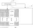


Sources:
- United States Patent and Trademark Office - verify current appl. status at the USPTO↗
Similar patent applications:
- » 20130009928
Liquid crystal display panel driving method, liquid crystal display device, and liquid crystal display driver including driving and setting a counter electrode for common inversion driving - » 20090051707
Liquid crystal display device drive method, liquid crystal display device, and television receiver - » 10204560
Liquid crystal display drive method and liquid crystal display - » 10221508
Liquid crystal display driving method and liquid crystal display apparatus - » 20050104831
TFT liquid crystal display driving method and TFT liquid crystal display driving module - » 20130321252
Liquid crystal display driving device and driving method of liquid crystal display driving device - » 20140168560
LIQUID CRYSTAL DISPLAY DEVICE, METHOD OF DRIVING LIQUID CRYSTAL DISPLAY DEVICE, AND METHOD OF ADJUSTING PULSE WAVEFORM SIGNAL - » 20100123832
Liquid crystal panel driving apparatus, liquid crystal display apparatus, method for driving liquid crystal display apparatus, drive condition setting program, and television receiver - » 20090109158
Liquid crystal display panel, common inversion driving method, liquid crystal display device, and liquid crystal display driver - » 20060227096
Driving circuit for liquid crystal display device, liquid crystal display device, method of driving liquid crystal display device, and electronic apparatus
Recent applications in this class:
- » 20250279078 2025-09-04
DISPLAY DEVICE - » 20250279077 2025-09-04
DISPLAY AND DISPLAY MANUFACTURING METHOD - » 20250273175 2025-08-28
FULL ARRAY LOCAL DIMMING GRAPHICS OPTIMIZATION FOR AUTOMOTIVE HEADS-UP DISPLAY - » 20250266008 2025-08-21
ELECTRONIC DEVICE - » 20250266007 2025-08-21
LOCAL DIMMING FOR PANEL DISPLAY DEVICES USING TWO-DIMENSIONAL LIGHT SOURCE ARRAY - » 20250252934 2025-08-07
DISPLAY APPARATUS - » 20250246160 2025-07-31
DATA PROCESSING METHOD AND DEVICE - » 20250246159 2025-07-31
Display and control method thereof - » 20250246158 2025-07-31
METHODS AND APPARATUS TO CONTROL BACKLIGHT DRIVERS - » 20250232737 2025-07-17
DISPLAY CONTROL METHOD, DISPLAY CONTROL APPARATUS, DISPLAY DEVICE, ELECTRONIC DEVICE, AND STORAGE MEDIUM
Recent applications for this Assignee:
- » 20250280692 2025-09-04
PIXEL STRUCTURE AND DISPLAY PANEL - » 20250280664 2025-09-04
DISPLAY PANEL AND DISPLAY DEVICE - » 20250221214 2025-07-03
DISPLAY PANEL AND DISPLAY DEVICE - » 20250221173 2025-07-03
DISPLAY PANEL AND METHOD OF MANUFACTURING THE SAME - » 20250204166 2025-06-19
DISPLAY PANEL AND DISPLAY DEVICE - » 20250176369 2025-05-29
DISPLAY PANEL AND MANUFACTURING METHOD THEREOF - » 20250176368 2025-05-29
DISPLAY PANEL AND DISPLAY DEVICE - » 20250160154 2025-05-15
DISPLAY PANEL AND METHOD OF MANUFACTURING THE SAME - » 20250151593 2025-05-08
DISPLAY PANEL - » 20250151529 2025-05-08
OLED DEVICE, MANUFACTURING METHOD FOR OLED DEVICE AND DISPLAY PANEL