Systems, Devices, and/or Methods for Managing Garments
US20200375264A1
2020-12-03
16/998,143
2020-08-20
Abstract:
Certain exemplary embodiments can provide a system comprising a shirt. The shirt comprises a shelf. The shelf is constructed to restrain motion of the shirt relative to a belt worn around a waist of a wearer of the shirt. The shelf is constructed to restrain motion of pants operatively engaged with the belt relative to the shirt.
Interested in similar patents?
Get notified when new applications in this technology area are published.
Classification:
A41F9/00 » CPC further
Belts, girdles, or waistbands for trousers or skirts
A41B1/08 » CPC main
Shirts Details
A41D1/06 » CPC further
Garments Trousers
Description
CROSS-REFERENCES TO RELATED APPLICATIONS
This application is a divisional application of, claims priority to, and incorporates by reference herein in its entirety, pending U.S. patent application Ser. No. 15/871,828 (Attorney Docket No. 1091-02), filed Jan. 15, 2018. This application is a continuation in part of, claims priority to, and incorporates by reference herein in its entirety, abandoned U.S. patent application Ser. No. 14/717,079 (Attorney Docket No. 1091-01), filed May 20, 2015.
BRIEF DESCRIPTION OF THE DRAWINGS
A wide variety of potential practical and useful embodiments will be more readily understood through the following detailed description of certain exemplary embodiments, with reference to the accompanying exemplary drawings in which:
FIG. 1A is a perspective view of an exemplary embodiment of a system 1000;
FIG. 1B is a perspective view of system 1000, which illustrates system 1000 without showing the belt;
FIG. 2 is an exploded view of exemplary system 1000;
FIG. 3 is a perspective view of an exemplary embodiment of a system 3000;
FIG. 4A is a cross-sectional view of exemplary system 3000;
FIG. 4B is a cross-sectional view of exemplary system 3000;
FIG. 5 is a perspective view of an exemplary embodiment of a system 5000;
FIG. 6 is a perspective view of an exemplary embodiment of a system 6000;
FIG. 7 is a frontal view of an exemplary embodiment of a system 7000;
FIG. 8 is a cross-sectional view of exemplary system 7000;
FIG. 9 is a perspective view of an exemplary embodiment of a system 9000;
FIG. 10 is a perspective view of an exemplary embodiment of a system 10000;
FIG. 11 is a cross-sectional view of an exemplary embodiment of a system 11000;
FIG. 12 is a frontal view of exemplary system 11000;
FIG. 13 is a rear exploded view of exemplary system 11000;
FIG. 14 is a rear view of exemplary system 11000; and
FIG. 15 is a flowchart of an exemplary embodiment of a method 15000.
DETAILED DESCRIPTION
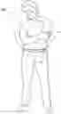
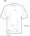
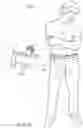
FIG. 1A is a perspective view of an exemplary embodiment of a system 1000, which comprises a shirt 1100. Shirt 1100 comprises a shelf 1200, which is constructed to restrain motion of shirt 1100 relative to a belt 1300 worn around a waist of a wearer 1400 of shirt 1100. Shelf 1200 is constructed to restrain motion of pants 1500 relative to shirt 1100, particularly when operatively engaged with belt 1300.
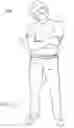
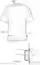
FIG. 1B is a perspective view of system 1000, which illustrates system 1000 without showing belt 1300. Shirt 1100 comprises shelf 1200, which is constructed to restrain motion of shirt 1100 relative to pants 1500 when shelf 1200 is operatively engaged with waistband 1900 of pants 1500.
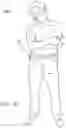
FIG. 2 is a perspective view of an exploded view of exemplary system 1000 without belt 1300. System 1000 comprises shirt 1100 that comprises shelf 1200 that has been donned by wearer 1400. Shelf 1200 is constructed to restrain motion of shirt 1100 relative to pants 1500 when shelf 1200 is operatively engaged with waistband 1900 of pants 1500.
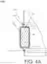
FIG. 3 is a perspective view of an exemplary embodiment of a system 3000, which comprises a shirt 3100 that comprises a shelf 3200. Exemplary embodiments of section 4 of system 3000 are illustrated in FIG. 4A and FIG. 4B. In certain exemplary embodiments, inserts 3300 shown in FIG. 4A and FIG. 4B can be substantially continuous substantially around an entire circumference of shirt 3100. In other embodiments, inserts 3300 shown in FIG. 4A and FIG. 4B can be installed as a set of six or more segmented inserts distributed substantially evenly around the circumference of shirt 3100. In such embodiments, shelf 3200 is comprised by plurality of elastomeric insert segments installed in a hem of shirt 3100.
FIG. 4A is a cross-sectional view of exemplary system 3000, which shows additional detail of an exemplary shelf 3200. Shelf 3200 defines a substantially flat surface 3500. Shelf 3200 is comprised by an insert 3300 installed via a hem 3400 of shirt 3100. In certain exemplary embodiments, insert 3300 can comprise an elastomeric material, such rubber. In other embodiments, insert 3300 can comprise a ceramic material. Insert 3300 comprises shelf 3200. Insert 3300 has a substantially rectangular cross-section. Certain exemplary embodiments comprise a second hem 3600. In other embodiments, fabric from a shirt can be folded around insert 3300 and a single hem 3400 can couple insert 3300 to shirt 3100.
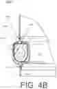
FIG. 4B is a cross-sectional view of exemplary system 3000, which shows additional detail of another exemplary shelf 3200. Shelf 3200 defines substantially flat surface 3500. Shelf 3200 is comprised by an insert 3300 installed via a hem 3400 of shirt 3100. Insert 3300 can be substantially solid, or can define a hollow internal area 3700. Insert 3300 comprises shelf 3200. Insert 3300 has a cross-section, which defines shelf 3200 and a rounded surface 3800 on an opposite side of the cross section from substantially flat surface 3500. Certain exemplary embodiments comprise a second hem 3600. In other embodiments, fabric from a shirt can be folded around insert 3300 and a single hem 3400 can couple insert 3300 to shirt 3100.
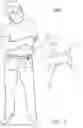
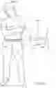
FIG. 5 is a perspective view of an exemplary embodiment of a system 5000, which comprises a shirt 5100. Shirt 5100 comprises hooks 5200, which function as a shelf, such as shelf 1200 of FIG. 1. When used in conjunction with a belt 5300, hooks 5200 are constructed to restrain motion of shirt 5100 relative to a belt 5300 worn around a waist of a wearer 5400 of shirt 5100. Hooks 5200 are constructed to restrain motion of pants 5500 operatively engaged with belt 5300 relative to shirt 5100. In certain exemplary embodiments, hooks 5200 can be metal hooks.
FIG. 6 is a perspective view of an exemplary embodiment of a system 6000, which comprises a shirt 6100. Shirt 6100 comprises hooks 6200, which function as a shelf, such as shelf 1200 of FIG. 1. When used in conjunction with a belt 6300, hooks 6200 are constructed to restrain motion of shirt 6100 relative to a belt 6300 worn around a waist of a wearer 6400 of shirt 6100. Hooks 6200 are constructed to restrain motion of pants 6500 operatively engaged with belt 6300 relative to shirt 6100. In certain exemplary embodiments, hooks 6200 can be metal hooks. In other embodiments, hooks 6200 can be made of any substance of suitable stiffness, such as metal, polymer, and/or plastic. Hooks 6200 can be fabric covered to improve appearance and/or wear resistance.
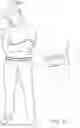
FIG. 7 is a frontal view of an exemplary embodiment of a system 7000, which comprises a shirt 7100 comprising a shelf 7200. Shelf comprising a substantially rectangular elastomer component 7300 (see FIG. 8). Shelf 7200 is constructed to restrain motion of shirt 7100 relative to a belt worn around a waist of a wearer of Shirt 7100, wherein the belt is placed above shelf 7200 when worn by the wearer. Shelf 7200 is constructed to restrain motion of shirt 7100 relative to pants operatively engaged with the belt. Shelf 7200 defines a substantially flat surface (see FIG. 8). Rectangular elastomer component 7300 can be installed in a hem 7400 of shirt 7100. Shelf 7200 is comprised by a plurality of segments of rectangular elastomer component 7300 installed in hem 7400 of shirt 7100. Certain exemplary systems can comprise the pants. Certain exemplary systems can comprise the belt.
FIG. 8 is a cross-sectional view of exemplary system 7000.
FIG. 9 is a perspective view of an exemplary embodiment of a system 9000, which comprises a plurality of hooks 9100 coupleable to a shirt 9200. Each of the plurality of hooks 9100 comprises:
-
- a shirt coupling portion (see shirt coupling portion 11100 of FIG. 11) that comprises a protrusion (see protrusion 11200 of FIG. 13) that defines a channel shaped notch (see channel shaped notch 11300 of FIG. 13), the protrusion having at least a partial substantially round cross section (as illustrated in detail in FIGS. 11, 12, 13, and 14); and
- a curved hook portion (see curved hook portion 11400 of FIG. 13) constructed to engage with a belt 9300 coupleable to pants 9400; and
- a plurality of elastomer O-rings (see elastomer O-ring 11500 of FIGS. 11 and 13), wherein each of the plurality of elastomer O-rings:
- is constructed to couple a corresponding hook of plurality of hooks 9100 to the shirt 9200 via engagement with the protrusion (see protrusion 11200 of FIG. 13); and
- rests in the channel shaped notch (see channel shaped notch 11300 of FIG. 13) of the corresponding hook of plurality of hooks 9100 when operatively coupled thereto.
In certain exemplary embodiments, the at least partial substantially round cross section defines a slot (see slot 11600 of FIGS. 12 and 13).
In certain exemplary embodiments, plurality of hooks 9100 is constructed to restrain motion of shirt 9200 relative to pants 9400 when pants 9400 and plurality of hooks 9100 are operatively coupled to shirt 9200 and engaged with belt 9300.
In certain exemplary embodiments, the system lacks an elastic band and/or any elastic band support system.
FIG. 10 is a perspective view of an exemplary embodiment of a system 10000.
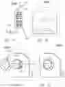
FIG. 11 is a cross-sectional view of an exemplary embodiment of a system 11000. In certain exemplary embodiments, shirt coupling portion 11100 can pass through an aperture in a shirt 11700. In other embodiments, protrusion 11200 can be pressed into a surface of a shirt lacking apertures and elastomer O-ring 11500 can engage with protrusion 11200 over a surface of fabric of shirt 11700.
FIG. 12 is a frontal view of exemplary system 11000.
FIG. 13 is a rear exploded view of exemplary system 11000.
FIG. 14 is a rear view of exemplary system 11000.
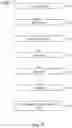
FIG. 15 is a flowchart of an exemplary embodiment of a method 15000. At activity 15100, an insert can be obtained. At activity 15200, a shirt can be made. The shirt can comprise a shelf. The shelf is constructed to restrain motion of the shirt relative to a belt worn around a waist of a wearer of the shirt. The shelf is constructed to restrain motion of pants operatively engaged with the belt relative to the shirt. At activity 15300, the insert can be installed in the shirt to form the shelf. At activity 15400, a wearer can don the shirt. At activity 15500, the wearer can don the pants. At activity 15600, the wearer can don the belt.
At activity 15600, certain exemplary embodiments can cause a wearer to couple a plurality of hooks to a shirt via a plurality of O-rings, wherein each of the plurality of hooks comprises:
a shirt coupling portion that comprises a protrusion that defines a channel, the protrusion having at least a partial substantially round cross section; and
a curved hook portion constructed to engage with a belt coupleable to pants.
In certain exemplary embodiments, each of the plurality of elastomer O-rings:
-
- is constructed to couple a corresponding hook of the plurality of hooks to the shirt via engagement with the protrusion; and
- rests in the cavity of the corresponding hook of the plurality of hooks when operatively coupled thereto.
In certain exemplary embodiments, the plurality of hooks is constructed to restrain motion of the shirt relative to the pants when the pants and the plurality of hooks are operatively coupled to the shirt and engaged with the belt. In certain exemplary embodiments, the system lacks an elastic band and/or any elastic band support system.
Definitions
When the following terms are used substantively herein, the accompanying definitions apply. These terms and definitions are presented without prejudice, and, consistent with the application, the right to redefine these terms during the prosecution of this application or any application claiming priority hereto is reserved. For the purpose of interpreting a claim of any patent that claims priority hereto, each definition (or redefined term if an original definition was amended during the prosecution of that patent), functions as a clear and unambiguous disavowal of the subject matter outside of that definition.
-
- a—at least one.
- activity—an action, act, step, and/or process or portion thereof
- adapter—a device used to effect operative compatibility between different parts of one or more pieces of an apparatus or system.
- and/or—either in conjunction with or in alternative to.
- apparatus—an appliance or device for a particular purpose
- associate—to join, connect together, and/or relate.
- belt—a band of flexible material constructed to encircle a waist of a wearer.
- can—is capable of, in at least some embodiments.
- cause—to produce an effect.
- channel shapes—having a cross section with a base and two upturned sides, wherein each of the two upturned sides join the base and thereby define a notch.
- comprising—including but not limited to.
- configure—to make suitable or fit for a specific use or situation.
- connect—to join or fasten together.
- constructed to—made suitable or fit for a specific use or situation.
- corresponding—related to and accompanying.
- coupleable—capable of being joined, connected, and/or linked together.
- coupling—linking in some fashion.
- cover—to place or spread something over a surface.
- cross-section—a view made by a plane cutting something transversely.
- curved—deviating from a straight line or plane surface without sharp breaks or angularity.
- define—to establish the outline, form, or structure of
- device—a machine, manufacture, and/or collection thereof.
- elastic band—a loop of rubber or other elastomer, which is usually ring shaped.
- elastomer—a rubbery material comprising long chainlike molecules, or polymers, that are capable of recovering their original shape after being deformed when a deforming force is removed.
- elastomeric—comprising a substance that is able to resume an original shape when a deforming force is removed (e.g., rubber).
- engage—to interlock with.
- fabric—a material having a texture of cloth.
- flat—defining a substantially planar surface.
- hem—a portion of a garment at an edge of the garment that is folded back and sewn.
- hook—a curved or angular piece constructed to suspend something.
- insert—something that is placed inside of something else.
- install—to place in a desired position.
- ledge—a projecting part constructed to engage with a belt on a wearer.
- make—to produce via a method.
- may—is allowed and/or permitted to, in at least some embodiments.
- metal—any of a class of elementary substances, which are crystalline when solid and are characterized by opacity and ductility.
- method—a process, procedure, and/or collection of related activities for accomplishing something.
- motion—a change of position from a first position to a second position.
- notch—an indentation.
- operatively—in a manner so as to effectively function.
- opposite side—a surface of an object that faces away from another surface.
- O-ring—an object having a shape of a torus; it is a loop of with a substantially round cross-section.
- pants—a garment constructed to cover a lower portion, including at least part of legs, of a body of a wearer.
- partial—not necessarily complete.
- plurality—the state of being plural and/or more than one.
- protrusion—a portion of an object that sticks out from a surface of the objects.
- rectangular—having a section characterized by edges that intersect at substantially right angles.
- relative—in relation to.
- rest—to rest substantially motionless relative to other parts of something.
- restrain—to resist motion of.
- round—defining a curved surface and having every part of the surface or circumference approximately equidistant from the center
- segment—an object having the form of a segment or sector of a circle.
- set—a related plurality.
- shelf—a surface constructed to support something.
- shirt—a garment constructed to cover an upper portion of a body of a wearer.
- slot—a groove.
- substantially—to a great extent or degree.
- support—to bear the weight of, especially from below.
- surface—an outer face of something.
- system—a collection of mechanisms, devices, machines, articles of manufacture, processes, data, and/or instructions, the collection designed to perform one or more specific functions.
- via—by way of and/or utilizing.
- waist—a human body part located between the ribs and the hips.
- wear—to don one or more articles of clothing.
- wearer—a person that don one or more articles of clothing.
Note
Still other substantially and specifically practical and useful embodiments will become readily apparent to those skilled in this art from reading the above-recited and/or herein-included detailed description and/or drawings of certain exemplary embodiments. It should be understood that numerous variations, modifications, and additional embodiments are possible, and accordingly, all such variations, modifications, and embodiments are to be regarded as being within the scope of this application.
Thus, regardless of the content of any portion (e.g., title, field, background, summary, description, abstract, drawing figure, etc.) of this application, unless clearly specified to the contrary, such as via explicit definition, assertion, or argument, with respect to any claim, whether of this application and/or any claim of any application claiming priority hereto, and whether originally presented or otherwise:
-
- there is no requirement for the inclusion of any particular described or illustrated characteristic, function, activity, or element, any particular sequence of activities, or any particular interrelationship of elements;
- no characteristic, function, activity, or element is “essential”;
- any elements can be integrated, segregated, and/or duplicated;
- any activity can be repeated, any activity can be performed by multiple entities, and/or any activity can be performed in multiple jurisdictions; and
- any activity or element can be specifically excluded, the sequence of activities can vary, and/or the interrelationship of elements can vary.
Moreover, when any number or range is described herein, unless clearly stated otherwise, that number or range is approximate. When any range is described herein, unless clearly stated otherwise, that range includes all values therein and all subranges therein. For example, if a range of 1 to 10 is described, that range includes all values therebetween, such as for example, 1.1, 2.5, 3.335, 5, 6.179, 8.9999, etc., and includes all subranges therebetween, such as for example, 1 to 3.65, 2.8 to 8.14, 1.93 to 9, etc.
When any claim element is followed by a drawing element number, that drawing element number is exemplary and non-limiting on claim scope. No claim of this application is intended to invoke paragraph six of 35 USC 112 unless the precise phrase “means for” is followed by a gerund.
Any information in any material (e.g., a United States patent, United States patent application, book, article, etc.) that has been incorporated by reference herein, is only incorporated by reference to the extent that no conflict exists between such information and the other statements and drawings set forth herein. In the event of such conflict, including a conflict that would render invalid any claim herein or seeking priority hereto, then any such conflicting information in such material is specifically not incorporated by reference herein.
Accordingly, every portion (e.g., title, field, background, summary, description, abstract, drawing figure, etc.) of this application, other than the claims themselves, is to be regarded as illustrative in nature, and not as restrictive, and the scope of subject matter protected by any patent that issues based on this application is defined only by the claims of that patent.
Claims
What is claimed is:1. A system comprising:
a plurality of hooks coupleable to a shirt, each of said plurality of hooks comprises:
a shirt coupling portion that comprises a protrusion that defines a channel shaped notch, the protrusion having at least a partial substantially round cross section; and
a curved hook portion constructed to engage with a belt coupleable to pants; and
a plurality of elastomer O-rings, wherein each of said plurality of elastomer O-rings:
is constructed to couple a corresponding hook of said plurality of hooks to said shirt via engagement with said protrusion; and
rests in said channel shaped notch of said corresponding hook of said plurality of hooks when operatively coupled thereto;
wherein:
said plurality of hooks is constructed to restrain motion of said shirt relative to said pants when said pants and said plurality of hooks are operatively coupled to said shirt and engaged with said belt; and
said system lacks a frame suspended from an elastic band.
2. The system of claim 1, wherein:
said partial substantially round cross section defines a slot.
3. The system of claim 1, further comprising:
said shirt.
4. The system of claim 1, further comprising:
said pants.
5. The system of claim 1, further comprising:
said belt.
6. A method comprising:
causing a wearer to couple a plurality of hooks to a shirt via a plurality of O-rings, wherein each of said plurality of hooks comprises:
a shirt coupling portion that comprises a protrusion that defines a channel, the protrusion having at least a partial substantially round cross section; and
a curved hook portion constructed to engage with a belt coupleable to pants; and
wherein each of said plurality of elastomer O-rings:
is constructed to couple a corresponding hook of said plurality of hooks to said shirt via engagement with said protrusion; and
rests in said channel of said corresponding hook of said plurality of hooks when operatively coupled thereto;
wherein:
said plurality of hooks is constructed to restrain motion of said shirt relative to said pants when said pants and said plurality of hooks are operatively coupled to said shirt and engaged with said belt.
Images & Drawings included:
Sources:
- United States Patent and Trademark Office - verify current appl. status at the USPTO↗
Similar patent applications:
- » 20160338414
Systems, Devices, and/or Methods for Managing Garments - » 20180132537
Systems, Devices, and/or Methods for Managing Garments
Recent applications in this class:
- » 20250049146 2025-02-13
SHIRT WITH CIGAR POCKETS - » 20240407471 2024-12-12
DEFORMABLE FRAMES FOR CLOTHING AND PERSONAL ITEMS - » 20240284993 2024-08-29
UPPER-BODY GARMENT WITH OPEN SLEEVE AND VENTED BACK CONSTRUCTIONS - » 20240284992 2024-08-29
DEVICE FOR FORMING A CROP TOP - » 20240245143 2024-07-25
Apparel with grip elements - » 20240188644 2024-06-13
TOURNIQUET SYSTEM - » 20240138492 2024-05-02
ELASTIC SUPPORT DEVICE AND OPTIONAL POWER SHIRT AND METHOD OF USE THEREOF - » 20240049806 2024-02-15
T-SHIRT WITH DETACHABLE PARTS - » 20240032608 2024-02-01
T-SHIRT WITH DETACHABLE PARTS - » 20230413925 2023-12-28
GARMENT INCLUDING STRETCH PANELS