ILLUMINATION CHOPPER
US20210282970A1
2021-09-16
17/332,087
2021-05-27
Abstract:
The present invention provides an illumination chopper which allows a user to operate on the nucleus of a crystalline lens with a small piece while securing visibility through a chopper which is mounted at one end of an illuminator to form a predetermined angle with the illuminator.
Interested in similar patents?
Get notified when new applications in this technology area are published.
Classification:
A61F9/00825 » CPC main
Methods or devices for treatment of the eyes; Devices for putting-in contact lenses; Devices to correct squinting; Apparatus to guide the blind; Protective devices for the eyes, carried on the body or in the hand; Methods or devices for eye surgery using laser for photodisruption
A61F2009/00887 » CPC further
Methods or devices for treatment of the eyes; Devices for putting-in contact lenses; Devices to correct squinting; Apparatus to guide the blind; Protective devices for the eyes, carried on the body or in the hand; Methods or devices for eye surgery using laser for treating a particular disease Cataract
A61F2009/0087 » CPC further
Methods or devices for treatment of the eyes; Devices for putting-in contact lenses; Devices to correct squinting; Apparatus to guide the blind; Protective devices for the eyes, carried on the body or in the hand; Methods or devices for eye surgery using laser adapted for treatment at a particular location Lens
A61F9/008 IPC
Methods or devices for treatment of the eyes; Devices for putting-in contact lenses; Devices to correct squinting; Apparatus to guide the blind; Protective devices for the eyes, carried on the body or in the hand; Methods or devices for eye surgery using laser
A61F9/007 » CPC further
Methods or devices for treatment of the eyes; Devices for putting-in contact lenses; Devices to correct squinting; Apparatus to guide the blind; Protective devices for the eyes, carried on the body or in the hand Methods or devices for eye surgery
A61B90/30 » CPC further
Instruments, implements or accessories specially adapted for surgery or diagnosis and not covered by any of the groups - , e.g. for luxation treatment or for protecting wound edges Devices for illuminating a surgical field, the devices having an interrelation with other surgical devices or with a surgical procedure
Description
CROSS-REFERENCE TO RELATED APPLICATIONS
This application is a Continuation of Ser. No. 17/122,241 filed on Dec. 15, 2020, which is a Continuation of U.S. application Ser. No. 14/901,131 filed on Dec. 28, 2015, now issued as U.S. Pat. No. 10,898,380, which is National Stage Entry of PCT/KR2014/009466 filed on Oct. 8, 2014, which claims priority to Korean Application No. 10-2013-0120806 filed on Oct. 10, 2013. The aforementioned applications are herein incorporated by reference in their entireties.
TECHNICAL FIELD
The present invention relates to an illumination chopper, and more particularly to an illumination chopper in which a nucleus of a lens is operated into small pieces while visibility is secured through a chopper mounted on one end of an illuminator to form a predetermined angle with respect to an illuminator.
BACKGROUND ART
In the medical field, an illuminator is generally mainly used when retinal surgery is conducted, and a chopper is used when cataract surgery is conducted.
Here, an illuminator or a chopper is used separately according to the surgery, and in the process of the surgery, the operator conducts the surgery while gripping the illuminator or the chopper for surgery in one hand and gripping an illumination device or an auxiliary tool for securing the field of view in the other hand.
That is, because the operator conducts surgery while gripping surgery tools in both hands in the above-mentioned surgery method, excessive force is applied to the hands of the operator, causing pain and deteriorating the accuracy of the surgery as well when the surgery is conducted for a long time.
In addition, because an illumination device emits light to the diseased part of the patient from the outside, efficiency is degraded as compared with the emitted light.
SUMMARY
Therefore, the present invention has been made in an effort to solve the above-mentioned problems, and provides an illumination chopper that separates the nucleus of a lens into small pieces while improving visibility through a coupling structure of a chopper that is mounted on one end of an illuminator in which an optical fiber is arranged at one end of the illuminator to form a predetermined angle with respect to the illuminator.
In order to solve the above-mentioned problems, an illumination chopper according to the present invention includes: an illuminator that emits light; a chopper that is mounted on one end of the illuminator to form a predetermined angle with respect to the illuminator; and a grip part that surrounds the illuminator. Visibility is changed according to the predetermined angle formed by the illuminator and the chopper.
Preferably, the illuminator includes: a body having a body hole through which light passes; and an optical fiber that is situated inside the body, and which emits the light towards one end of the body.
Preferably, the illumination chopper includes: a power supply for supplying electric power to the optical fiber; and a power connection part that electrically connects the optical fiber and the power supply.
Preferably, when the predetermined angle is an acute angle, the light emitted from the illuminator illuminates a front side of the illuminator.
Preferably, when the predetermined angle is an obtuse angle, the light emitted from the illuminator is refracted by the chopper to illuminate a periphery of the chopper.
As described above, according to the present invention, surgery that separates the nucleus of a lens into small pieces through a chopper while improving visibility by emitting light from the interior of an eyeball can be performed.
BRIEF DESCRIPTION OF THE DRAWINGS
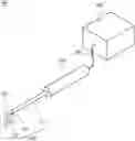
FIG. 1 is a perspective view from one side, which illustrates an illumination chopper according to a first embodiment of the present invention.
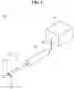
FIG. 2 is a front view from one side, which illustrates the illuminator of FIG. 1.
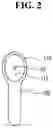
FIG. 3 is a perspective view from one side, which illustrates an illumination chopper according to a second embodiment of the present invention.
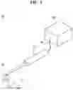
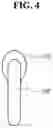
FIG. 4 is a front view from one side, which illustrates the illuminator of FIG. 3.
DETAILED DESCRIPTION
Elements of an illumination chopper according to the present invention may be used integrally or separately if necessary. Further, some elements may be omitted according to usage.
Preferred embodiments of the illumination chopper 100 according to the present invention will be described with reference to FIGS. 1 to 4. In the process, the thicknesses of the lines of the drawings or the sizes of the elements may be exaggerated for clarity and convenience of description. Further, the following terms are terms that are defined in consideration of their functions in the present invention, and may vary depending on an intention or customs of the user or the manager. Therefore, the definition of the terms should be made based on the overall contents of the specification.
First Embodiment
Hereinafter, an illumination chopper 100 according to a first embodiment of the present invention will be described with reference to FIGS. 1 and 2.
The illumination chopper 100 according to the first embodiment of the present invention includes an illuminator 110 that emits light, a chopper 120 that is mounted on one end of the illuminator 110 to form a predetermined angle with the illuminator 110, a grip part 130 that surrounds the illuminator 110, a power supply 140 that is electrically connected the illuminator 110, and a power connection part 150 that electrically connects the illuminator 110 and the power supply 140.
The illuminator 110 includes a body 111, a body hole 112, and optical fibers 113.
The body 111 is a kind of a tool that is generally used when cataract surgery is conducted, and has the form of a hollow tube. The body 111 includes the body hole 112 through which light passes, and a plurality of optical fibers 113 for emitting light to the outside are situated in the interior of the body 111.
The body hole 112 is a hole situated inside the body 111, and the plurality of optical fibers 113 are situated in the body hole 112.
The optical fibers 113 are situated in the interior of the body 111, and light is emitted towards one end of the body 111.
The chopper 120 is mounted on one end of the illuminator 110 and is arranged to form a predetermined angle with the illuminator 110.
In more detail, as illustrated in FIG. 1, the chopper 120 may be arranged so as not to block light emitted from the optical fibers 113.
That is, in the first embodiment of the present invention, the predetermined angle is an acute angle, and the light emitted from the illuminator 110 illuminates the front side of the illuminator 110.
The coupling structure allows the operator to emit light into an eyeball by using the illuminator 110 to improve visibility, and to conduct cataract surgery with the chopper 120 at the same time.
It is preferable that the grip part 130 is formed to surround the illuminator 110 and is formed of a resilient material. The grip part 130 helps the operator conduct cataract surgery or the like while the operator grips the grip part 130 with one hand thereof.
The power supply 140 is a unit for supplying electric power to the optical fibers 113, and is electrically connected to the power connection part 150. The power supply 140 may be any unit that can supply electric power.
The power connection part 150 is an electric wire that electrically connects the optical fibers 113 and the power supply 140.
Second Embodiment
Hereinafter, an illumination chopper 100′ according to a second embodiment of the present invention will be described with reference to FIGS. 3 and 4, in which all the elements except for the chopper 120′ are the same as those of the first embodiment and will be described with reference to the second embodiment of the present invention.
The illumination chopper 100′ according to the second embodiment of the present invention includes an illuminator 110′ that emits light, a chopper 120′ that is mounted on one end of the illuminator 110′ to form a predetermined angle with respect to the illuminator 110′, a grip part 130′ that surrounds the illuminator 110′, a power supply 140′ that is electrically connected the illuminator 110′, and a power connection part 150′ that electrically connects the illuminator 110′ and the power supply 140′.
The chopper 120′ is mounted on one end of the illuminator 110′ and is arranged to form a predetermined angle with respect to the illuminator 110′.
That is, in the second embodiment of the present invention, the predetermined angle is an obtuse angle, and the light emitted from the illuminator 110′ is refracted by the chopper 120′ to illuminate a periphery of the chopper 120′.
In more detail, as illustrated in FIG. 3, the chopper 120′ is configured such that the light emitted from the optical fibers 113′ is refracted by the chopper 120′ so that the field of view around the chopper 120′ is secured.
The coupling structure allows the operator to emit light into an eyeball by using the illuminator 110′ to improve visibility, and to conduct cataract surgery with the chopper 120′ at the same time.
Here, the choppers 120 and 120′ according to the first and second embodiments of the present invention are somewhat different in the coupling relationships with the illuminators 110 and 110′, and it is apparent that the structure may be fixed after being variably adjusted to provide the operator with convenience during cataract surgery.
Although the present invention has been described with reference to the preferred embodiments of the present invention, it will be understood that the present invention may be variously corrected and modified by those skilled in the art to which the present invention pertains without departing from the spirit and area described in the claims.
Claims
What is claimed is:1. A device for use in eye surgery comprising:
an illuminator including a first end and a second end and being configured to emit light through the second end; and
a chopper that is fixedly mounted to the illuminator while being bent in a substantially downward direction at a predetermined angle with respect to the illuminator.
2. The device of claim 1, wherein the predetermined angle is an obtuse angle.
3. The device of claim 1, wherein the predetermined angle is a substantially right angle.
4. The device of claim 1, wherein the chopper has an oval cross-section.
5. The device of claim 1, wherein the illuminator and the chopper are integrally formed.
6. The device of claim 1, further comprising an optical fiber connected to the illuminator for transmitting the light therethrough.
7. The device of claim 1, further comprising a grip part that surrounds at least a portion of the illuminator.
8. The device of claim 7, wherein the illuminator, the chopper, and the grip part are integrally formed.
Images & Drawings included:
Sources:
- United States Patent and Trademark Office - verify current appl. status at the USPTO↗
Similar patent applications:
- » 20160143782
Illumination chopper - » 20210093484
ILLUMINATION CHOPPER - » 20210282969
ILLUMINATION CHOPPER - » 20210282971
ILLUMINATION CHOPPER - » 20210282972
ILLUMINATION CHOPPER - » 20210282973
ILLUMINATION CHOPPER
Recent applications in this class:
- » 20250073079 2025-03-06
SYSTEM, METHOD AND MATERIAL COMPOSITION FOR USE IN CORRECTION OF EYE CONDITIONS - » 20250064642 2025-02-27
Automated laser iridotomy - » 20250000702 2025-01-02
NON-INVASIVE AND MINIMALLY INVASIVE LASER SURGERY FOR THE REDUCTION OF INTRAOCULAR PRESSURE IN THE EYE - » 20240423839 2024-12-26
MEMBRANE REMOVAL DEVICE - » 20240325201 2024-10-03
APPARATUS FOR THE TREATMENT OF GLAUCOMA USING VISIBLE AND INFRARED ULTRASHORT LASER PULSES - » 20240299215 2024-09-12
INTEGRATED SURGICAL SYSTEM AND METHOD FOR TREATMENT IN THE IRIDO-CORNEAL ANGLE OF THE EYE - » 20240245553 2024-07-25
SYSTEMS FOR THE TREATMENT OF GLAUCOMA USING VISIBLE AND INFRARED ULTRASHORT LASER PULSES - » 20240207099 2024-06-27
LASER SYSTEM AND METHOD FOR CORRECTION OF INDUCED ASTIGMATISM - » 20240197534 2024-06-20
METHOD FOR PROVIDING CONTROL DATA FOR AN OPHTHALMOLOGICAL LASER FOR PROVIDING A TRANSITION ZONE BETWEEN INTERFACES - » 20240139032 2024-05-02
CORNEAL TOPOGRAPHY MEASUREMENT AND ALIGNMENT OF CORNEAL SURGICAL PROCEDURES