Generator and double-swirl mixing device thereof
US20210285356A1
2021-09-16
16/328,322
2016-11-18
✅ Patent granted
US 11,365,666 B2
2022-06-21
WO; PCT/CN2016/106360; 20161118
WO; WO2018/040300; 20180308
Audrey B. Walter
Cantor Colburn LLP
2037-05-25
Abstract:
An engine and a double-swirl mixing device thereof are provided. The double-swirl mixing device includes a mixing tube configured to mix exhaust gas with urea, a tapered mixer including a tapered tube having an outlet end extending into the mixing tube, and a plurality of tapered swirl plates which are arranged along a circumferential direction on a side wall of the tapered tube, and a fan-type blade arranged at the outlet end of the tapered tube, and a diameter of an inlet end of the tapered tube is smaller than a diameter of the outlet end of the tapered tube.
Inventors:
- Wei Gao 4 🇨🇳 Shandong, China
- Xuguang TAN 9 🇨🇳 Shandong, China
- Dongsheng WANG 2 🇨🇳 Shandong, China
- Fengshuang WANG 2 🇨🇳 Shandong, China
- Yibao WANG 3 🇨🇳 Shandong, China
- Xuquang TAN 1 🇨🇳 Weifang, Shandong, China
- Yibao WANG 2 🇨🇳 Weifang, Shandong, China
- Xiaoli ZHANG 2 🇨🇳 Weifang, Shandong, China
- Fengshuang WANG 1 🇨🇳 Weifang, Shandong, China
- Dongsheng WANG 1 🇨🇳 Weifang, Shandong, China
- Hao ZHANG 1 🇨🇳 Weifang, Shandong, China
- Suying ZHANG 1 🇨🇳 Weifang, Shandong, China
- Wei GAO 1 🇨🇳 Weifang, Shandong, China
- Xiaoli Zhang 1 🇨🇳 Shandong, China
- Hao Zhang 3 🇨🇳 Shandong, China
- Suying Zhang 1 🇨🇳 Shandong, China
Assignee:
- Weichai Power Co., Ltd. 29 🇨🇳 Shandong, China
Applicant:
Interested in similar patents?
Get notified when new applications in this technology area are published.
Classification:
F01N3/2892 » CPC main
Exhaust or silencing apparatus having means for purifying, rendering innocuous, or otherwise treating exhaust for rendering innocuous by thermal or catalytic conversion of noxious components of exhaust characterised by constructional aspects of converting apparatus; Construction of catalytic reactors Exhaust flow directors or the like, e.g. upstream of catalytic device
B01F23/2132 » CPC further
Mixing according to the phases to be mixed, e.g. dispersing or emulsifying; Mixing gases with liquids by introducing liquids into gaseous media by spraying or atomising of the liquids using nozzles
B01F25/103 » CPC further
Flow mixers; Mixers for falling materials, e.g. solid particles; Mixing by creating a vortex flow, e.g. by tangential introduction of flow components with additional mixing means other than vortex mixers, e.g. the vortex chamber being positioned in another mixing chamber
B01F2025/931 » CPC further
Flow mixers; Mixers for falling materials, e.g. solid particles; Arrangements, nature or configuration of flow guiding elements Flow guiding elements surrounding feed openings, e.g. jet nozzles
F01N3/2066 » CPC further
Exhaust or silencing apparatus having means for purifying, rendering innocuous, or otherwise treating exhaust for rendering innocuous by thermal or catalytic conversion of noxious components of exhaust characterised by methods of operation; Control specially adapted for catalytic conversion ; Methods of operation or control of catalytic converters Selective catalytic reduction [SCR]
F01N2610/02 » CPC further
Adding substances to exhaust gases the substance being ammonia or urea
F01N3/28 IPC
Exhaust or silencing apparatus having means for purifying, rendering innocuous, or otherwise treating exhaust for rendering innocuous by thermal or catalytic conversion of noxious components of exhaust characterised by constructional aspects of converting apparatus Construction of catalytic reactors
B01D53/94 IPC
Separation of gases or vapours; Recovering vapours of volatile solvents from gases; Chemical or biological purification of waste gases, e.g. engine exhaust gases, smoke, fumes, flue gases, aerosols,; Chemical or biological purification of waste gases of engine exhaust gases by catalytic processes
B01F23/21 IPC
Mixing according to the phases to be mixed, e.g. dispersing or emulsifying; Mixing gases with liquids by introducing liquids into gaseous media
B01F25/10 IPC
Flow mixers; Mixers for falling materials, e.g. solid particles Mixing by creating a vortex flow, e.g. by tangential introduction of flow components
F01N3/20 IPC
Exhaust or silencing apparatus having means for purifying, rendering innocuous, or otherwise treating exhaust for rendering innocuous by thermal or catalytic conversion of noxious components of exhaust characterised by methods of operation; Control specially adapted for catalytic conversion ; Methods of operation or control of catalytic converters
B01F23/213 IPC
Mixing according to the phases to be mixed, e.g. dispersing or emulsifying; Mixing gases with liquids by introducing liquids into gaseous media by spraying or atomising of the liquids
B01F25/00 IPC
Flow mixers; Mixers for falling materials, e.g. solid particles
B01F25/00 IPC
Mixers
B01D53/9431 » CPC further
Separation of gases or vapours; Recovering vapours of volatile solvents from gases; Chemical or biological purification of waste gases, e.g. engine exhaust gases, smoke, fumes, flue gases, aerosols,; Chemical or biological purification of waste gases of engine exhaust gases by catalytic processes; Removing only nitrogen compounds; Nitrogen oxides Processes characterised by a specific device
Description
CROSS REFERENCE TO RELATED APPLICATIONS
This is the U.S. national stage of International Application No. PCT/CN2016/106360, filed on Nov. 18, 2016. Priority under 35 U.S.C. § 119(a) and 35 U.S.C. § 365(b) is claimed from Chinese Application No. 201610769654.X, filed on Aug. 30, 2016, the disclosures all of which are also incorporated herein by reference.
FIELD
The present application relates to the technical field of exhaust gas treatment, specifically to an engine and a double-swirl mixing device thereof.
BACKGROUND
Selective catalytic reduction technology (SCR) is a means of preferentially reducing NOx into N2 with a high selectivity with the aid of a reducing agent such as ammonia, ammonium hydroxide, urea or hydrocarbons under a condition that the oxygen concentration is two orders of magnitudes higher than the NOx concentration. The function of catalysis is to decrease the activation energy of decomposition reaction so that the reaction temperature can be lowered to a suitable temperature range.
As urea is nontoxic, does not have great influence on the environment and human health, and is convenient for storage and transportation, urea is more suitable to be used as the reducing agent for NOx in the vehicle SCR system.
Sediments such as urea crystal stone and etc. are easily generated when a diesel vehicle with the SCR system is operating under a low load condition, and this problem is a main factor that effects the stable operation of the vehicle. When the vehicle is running, due to insufficient atomization, uneven mixing or insufficient decomposition of urea, the jetted urea droplet cannot be transformed into NH3 in time, but produces side products, resulting in instable reduction reaction, thereby affecting the uniformity and conversion efficiency of the discharge of NOx.
Thus, how to solve the problems in the conventional technology that urea is apt to deposit, be insufficiently atomized, and be unevenly mixed with the exhaust gas has become an important technical problem to be solved by the person skilled in the art.
SUMMARY
In view of this, an object of the present application is to provide a double-swirl mixing device, which can efficiently avoids the problems that urea is apt to deposit, be insufficiently atomized, and be unevenly mixed with the exhaust gas. The object of the present application is also to provide an engine having the double-swirl mixing device.
A double-swirl mixing device provided by the present application includes:
a mixing tube configured to mix exhaust gas with urea;
a tapered mixer, including a tapered tube having an outlet end extending into the mixing tube, and a plurality of tapered swirl plates which are arranged along a circumferential direction on a side wall of the tapered tube, and a diameter of an inlet end of the tapered tube being smaller than a diameter of the outlet end of the tapered tube; and
a fan-type blade arranged at the outlet end of the tapered tube.
Preferably, the number of the fan-type blade is plural and the plurality of fan-type blades are evenly distributed around a center line of the mixing tube.
The present application also provides an engine having the double-swirl mixing device.
In the technical solution provided by the present application, the mixing device includes the tapered swirl plates and the fan-type blades, the fan-type blades have a structure similar to the blade structure of an electric fan in the conventional technology. The function of the tapered swirl plates is to rotate the entered exhaust gas at high speed, to warp and take away the jetted urea. The diameter of the inlet end of the tapered tube is smaller than the diameter of the outlet end of the tapered tube, thus compared with the structure having two ends with equal diameters, in this solution the outlet end of the tapered tube weakens the strength of the rotating airflow, reduces the urea droplets landed at a rear end of a urea mixing tube under the action of the high-speed rotating airflow, and reduces the contact between urea and the wall surface of the urea mixing tube, therefore preventing the generation of the urea crystal. After passing through the outlet end of the tapered mixer, part of the airflow flows through the fan-type blades, which accelerates the flowing and rotating of airflow near the wall surface of the mixing tube, and timely takes away the urea liquid film that is thrown on the wall surface of the mixing tube under the action of strong swirling function of the tapered swirl plates, thereby further lowering the risk of generation of the urea crystal and improving the mixing between urea and airflow.
BRIEF DESCRIPTION OF DRAWINGS
For more clearly illustrating embodiments of the present application or the technical solution in the conventional technology, drawings referred to describe the embodiments or the conventional technology will be briefly described hereinafter. Apparently, the drawings in the following description are only several embodiments of the present application, and for the person skilled in the art other drawings may be obtained based on these drawings without any creative efforts.
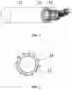
FIG. 1 is an overall view of a double-swirl mixing device according to an embodiment of the present application.
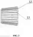
FIG. 2 is a front schematic view of a tapered mixer according to an embodiment of the present application.
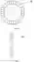
FIG. 3 is a left schematic view of the tapered mixer according to the embodiment of the present application.
FIG. 4 is a front schematic view of fan-type blades according to an embodiment of the present application.
FIG. 5 is a left schematic view of the fan-type blades according to the embodiment of the present application.
REFERENCE NUMERALS IN FIG. 1 THROUGH FIG. 5
-
- mixing tube 11,
- tapered tube 12,
- tapered swirl plate 13,
- fan-type blade 14.
DETAILED DESCRIPTION
An object of the embodiments of present application is to provide a double-swirl mixing device, which can efficiently avoids problems that urea is apt to deposit, be insufficiently atomized, and be unevenly mixed with the exhaust gas. The object of the embodiments of the present application is also to provide an engine having the double-swirl mixing device.
The embodiments will be illustrated in conjunction with attached figures hereinafter. Furthermore, the embodiments herein do not limit the present application as set forth in the claims. in addition, the entire contents of the configurations shown in the following embodiments are not limited to necessary contents for the solutions of the present application as set forth in the claims.
Reference is made to FIG. 1 through FIG. 5, a double-swirl mixing device according to this embodiment includes a mixing tube 11, a tapered mixer and fan-type blades 14.
The mixing tube 11 is used to mix the exhaust gas with urea. The tapered mixer includes a tapered tube 12 having an outlet end extending into the mixing tube 11, and multiple tapered swirl plates 13 which are distributed along the circumferential direction on a side wall of the tapered tube 12. The diameter of an inlet end of the tapered tube 12 is smaller than the diameter of the outlet end of the tapered tube 12. The fan-type blades 14 are arranged at the outlet end of the tapered tube 12.
In the technical solution provided by this embodiment, the fan-type blades 14 have a structure similar to the blade structure of an electric fan in the conventional technology. The function of the tapered swirl plates 13 is to rotate the entered exhaust gas at high speed, to warp and take away the jetted urea. The diameter of the inlet end of the tapered tube 12 is smaller Wan the diameter of the outlet end of the tapered tube 12, thus compared with the structure having two ends with equal diameters, in this embodiment the outlet end of the tapered tube 12 weakens the strength of the rotating airflow, reduces the urea droplets landed at a rear end of a urea mixing tube under the action of the high-speed rotating airflow, and reduces the contact between urea and the wall surface of the urea mixing tube 11, therefore preventing the generation of the urea crystal. After passing through the outlet end of the tapered mixer, part of the airflow flows through the fan-type blades 14, which accelerates the flowing and rotating of airflow near the wall surface of the mixing tube 11, and timely takes away the urea liquid film that is thrown on the wall surface of the mixing tube 11 under the action of strong swirling function of the tapered swirl plates, thereby further lowering the risk of generation of the urea crystal and improving the mixing between urea and airflow.
It should be illustrated that for engines of different displacements and uses, the double-swirl mixing device provided by this embodiment can adjust angles, lengths and the number of the tapered swirl plates 13 and the blades of the fan-type blades 14, to realize reasonable distribution of airflow.
An engine is further provided according to this embodiment, which includes the double-swirl mixing device as described in the above embodiment. With such an arrangement, the engine provided by this embodiment has an exhaust gas treatment device that can efficiently avoids problems that urea is apt to deposit, be insufficiently atomized, and be unevenly mixed with the exhaust gas. The derivation process of the beneficial effects is substantially similar to the derivation process of the beneficial effects brought by the double-swirl mixing device, and thus will not be described again herein.
Based on the above description of the disclosed embodiments, the person skilled in the art is capable of carrying out or using the present application. It is obvious for the person skilled in the art to make many modifications to these embodiments. The general principle defined herein may be applied to other embodiments without departing from the spirit or scope of the present application. Therefore, the present application is not limited to the embodiments illustrated herein, but should be defined by the broadest scope consistent with the principle and novel features disclosed herein.
Claims
1. A double-swirl mixing device, comprising:
a mixing tube configured to mix exhaust gas with urea;
a tapered mixer, comprising a tapered tube having an outlet end extending into the mixing tube, and a plurality of tapered swirl plates which are arranged along a circumferential direction on a side wall of the tapered tube, and a diameter of an inlet end of the tapered tube being smaller than a diameter of the outlet end of the tapered tube; and
a fan-type blade arranged at the outlet end of the tapered tube.
2. The double-swirl mixing device according to claim 1, wherein the number of the fan-type blade is plural and the plurality of fan-type blades are evenly distributed around a center line of the mixing tube.
3. An engine, comprising the double-swirl mixing device according to claim 1.
4. An engine, comprising the double-swirl mixing device according to claim 2.
Images & Drawings included:

Sources:
- United States Patent and Trademark Office - verify current appl. status at the USPTO↗
Recent applications in this class:
- » 20250198320 2025-06-19
INTERNAL ENGINE COMBUSTION SYSTEM - » 20250179954 2025-06-05
Mixers For Exhaust Aftertreatment Systems - » 20250137395 2025-05-01
COLD START CATALYST BYPASS SYSTEM - » 20250122820 2025-04-17
EXHAUST MIXER ASSEMBLY - » 20250101899 2025-03-27
MIXER ARRANGEMENT FOR MIXING AN INJECTION MEDIUM INJECTABLE BY AN INJECTOR WITH THE EXHAUST GAS OF AN INTERNAL COMBUSTION ENGINE - » 20250059903 2025-02-20
Mixer Assembly - » 20250052184 2025-02-13
Exhaust gas aftertreatment mixer - » 20250052183 2025-02-13
CHAMBER MIXER FOR AN EXHAUST AFTER-TREATMENT SYSTEM OF A MOTOR VEHICLE - » 20240401512 2024-12-05
SYSTEMS AND METHODS FOR OPERATING PASSIVE NITROGEN OXIDE ADSORBERS IN EXHAUST AFTERTREATMENT SYSTEMS - » 20240328340 2024-10-03
SWIRL STRUCTURE-BASED EXHAUST AFTERTREATMENT DEVICE FOR UNDERGROUND MINING DIESEL VEHICLE
Recent applications for this Assignee:
- » 20240401543 2024-12-05
Airway structure, cylinder cover, and miller-profile engine - » 20240360798 2024-10-31
Control method for combustion system, combustion system, and diesel engine - » 20240352901 2024-10-24
Cylinder deactivation control method and apparatus of engine, and engine - » 20240352900 2024-10-24
Cylinder deactivation control method and apparatus of engine, and engine - » 20240352886 2024-10-24
A CONTROL METHOD FOR AN AIR INTAKE INTERCOOLER OF AN ENGINE AND A CONTROL SYSTEM THEREOF - » 20240254939 2024-08-01
Control method for combustion system, combustion system and engine - » 20240229750 2024-07-11
EGR mixing and adjusting apparatus and internal combustion engine - » 20240125262 2024-04-18
Urea pump, and control method and control system for urea pump - » 20240117780 2024-04-11
Method for controlling combustion system, combustion system, and internal combustion engine - » 20240026837 2024-01-25
Composite coating, piston, engine and vehicle