Cab and fasteners for vehicle cab
US20220063733A1
2022-03-03
17/524,434
2021-11-11
✅ Patent granted
US 11,926,365 B2
2024-03-12
-
-
Pinel E Romain
Billion & Armitage
2042-09-23
Abstract:
A utility vehicle including a cab assembly, a roof assembly, a windshield assembly, a rear window assembly, and two or more couplers attached to one or more ROPS members. The couplers are each aligned with and are releasably connected with a buckle insert attached to one or more of the roof assembly, windshield assembly, rear window assembly and doors of the cab assembly.
Inventors:
- Leigh Raymond Collyer 6 🇺🇸 Sauk Rapids, MN, United States
- Matthew Eastwood 3 🇺🇸 Milaca, MN, United States
- Aaron Lee Swanson 2 🇺🇸 Bemidji, MN, United States
Assignee:
- Arctic Cat Inc. 175 🇺🇸 Thief River Falls, MN, United States
Applicant:
Interested in similar patents?
Get notified when new applications in this technology area are published.
Classification:
F16B2/24 IPC
Friction-grip releasable fastenings; Clips, i.e. with gripping action effected solely by the inherent resistance to deformation of the material of the fastening of resilient material, e.g. rubbery material of metal
B60J5/047 » CPC further
Doors arranged at the vehicle sides characterised by the opening or closing movement
B60J7/106 » CPC further
Non-fixed roofs; Roofs with movable panels, e.g. rotary sunroofs of non-sliding type, i.e. movable or removable roofs or panels, e.g. let-down tops or roofs capable of being easily detached or of assuming a collapsed or inoperative position readily detachable, e.g. tarpaulins with frames, or fastenings for tarpaulins readily detachable hard-tops
B60J7/165 » CPC further
Non-fixed roofs; Roofs with movable panels, e.g. rotary sunroofs of non-sliding type, i.e. movable or removable roofs or panels, e.g. let-down tops or roofs capable of being easily detached or of assuming a collapsed or inoperative position non-foldable and rigid, e.g. a one-piece hard-top or a single rigid roof panel for covering the passenger compartment of non-convertible vehicles at least a major part of the roof being lifted on all corners
B60J7/194 » CPC further
Non-fixed roofs; Roofs with movable panels, e.g. rotary sunroofs; Locking arrangements for rigid panels for locking detachable hard-tops or removable roof panels to the vehicle body
F16B5/0685 » CPC further
Joining sheets or plates, e.g. panels, to one another or to strips or bars parallel to them by means of clamps or clips Joining sheets or plates to strips or bars
B60Y2200/20 » CPC further
Type of vehicle Off-Road Vehicles
F16B2/245 » CPC further
Friction-grip releasable fastenings; Clips, i.e. with gripping action effected solely by the inherent resistance to deformation of the material of the fastening of resilient material, e.g. rubbery material of metal of sheet metal external, i.e. with contracting action
B62D27/06 » CPC main
Connections between superstructure sub-units readily releasable
B60J5/04 IPC
Doors arranged at the vehicle sides
B60J7/19 IPC
Non-fixed roofs; Roofs with movable panels, e.g. rotary sunroofs; Locking arrangements for rigid panels
B60J7/16 IPC
Non-fixed roofs; Roofs with movable panels, e.g. rotary sunroofs of non-sliding type, i.e. movable or removable roofs or panels, e.g. let-down tops or roofs capable of being easily detached or of assuming a collapsed or inoperative position non-foldable and rigid, e.g. a one-piece hard-top or a single rigid roof panel
B60J1/04 » CPC further
Windows; Windscreens; Accessories therefor arranged at the vehicle front, e.g. structure of the glazing, mounting of the glazing adjustable
B60J7/10 IPC
Non-fixed roofs; Roofs with movable panels, e.g. rotary sunroofs of non-sliding type, i.e. movable or removable roofs or panels, e.g. let-down tops or roofs capable of being easily detached or of assuming a collapsed or inoperative position readily detachable, e.g. tarpaulins with frames, or fastenings for tarpaulins
B60J7/11 » CPC further
Non-fixed roofs; Roofs with movable panels, e.g. rotary sunroofs of non-sliding type, i.e. movable or removable roofs or panels, e.g. let-down tops or roofs capable of being easily detached or of assuming a collapsed or inoperative position readily detachable, e.g. tarpaulins with frames, or fastenings for tarpaulins Removable panels, e.g. sunroofs
F16B5/06 IPC
Joining sheets or plates, e.g. panels, to one another or to strips or bars parallel to them by means of clamps or clips
B60Y2200/124 » CPC further
Type of vehicle; Road Vehicles; Motorcycles, Trikes; Quads; Scooters Buggies, Quads
Description
CROSS-REFERENCE
This application is a continuation of U.S. patent application Ser. No. 16/839,516 filed Apr. 3, 2020, which is a continuation of U.S. patent application Ser. No. 15/927,719, filed Mar. 21, 2018, titled “Cab and Fasteners for Vehicle Cab”, now U.S. Pat. No. 10,717,474 issued Jul. 21, 2020, which claims the benefit of U.S. Provisional Application No. 62/474,556, filed on Mar. 21, 2017, and which applications are incorporated herein by reference. This application is also related to the subject matter of U.S. patent application Ser. No. 15/927,524, filed Mar. 21, 2018, titled, “Off-Road Utility Vehicle”; having inventors Devin Joseph Danielson, Adam Christian Krone, Nathan Len Wiater, Aaron Lee Swanson, Erick John Halvorson, Douglas Robert Grangroth, Kevin James Miller, Jared Richard Spindler, Leigh Raymond Collyer, Donald Scott Hansen, and Joseph Patrick Wood, the contents of which are herein incorporated by reference.
SUMMARY
A utility vehicle including a cab assembly, a roof assembly, a windshield assembly, a rear window assembly, and two or more couplers attached to one or more ROPS members. The couplers are each aligned with and are releasably connected with a buckle insert attached to one or more of the roof assembly, windshield assembly, rear window assembly and doors of the cab assembly.
BRIEF DESCRIPTION OF THE DRAWINGS
In the drawings, which are not necessarily drawn to scale, like numerals may describe similar components in difference views. The drawings illustrate generally, by way of example, but not by way of limitation, various embodiments discussed in the present document.
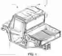
FIG. 1 shows a perspective view of a partial utility vehicle, according to some embodiments.
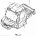
FIG. 2 shows a perspective view of a partial utility vehicle, according to some embodiments.
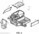
FIG. 3 shows an exploded view of a partial utility vehicle, according to some embodiments.
FIG. 4 shows an exploded view of a partial utility vehicle, according to some embodiments.
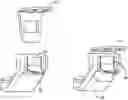
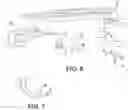
FIG. 5 shows an exploded view of a roof assembly, according to some embodiments.
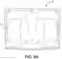
FIG. 6A shows a bottom perspective view of a roof assembly, according to some embodiments.
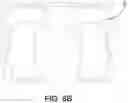
FIG. 6B shows a top perspective view of a roof assembly, according to some embodiments.
FIG. 7 shows a side view of couplers, according to some embodiments.
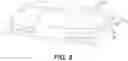
FIG. 8 shows a perspective view of a roof assembly, according to some embodiments.
FIG. 9 shows a partial perspective view of a windshield assembly, according to some embodiments.
FIGS. 10A-D show views of buckle inserts and couplers, according to some embodiments.
DETAILED DESCRIPTION
As shown in perspective views FIGS. 1-2 and exploded views FIGS. 3-4, a utility vehicle 10 comprises at least a cab assembly 12 which, in some embodiments, includes one or more doors 14, rear window assembly 16, windshield assembly 18, and roof assembly 20. In some embodiments, one or more of the doors 14, rear window assembly 16, windshield assembly 18, and roof assembly 20 are removable from the utility vehicle 10 by removing or actuating a fastener.
With regard to FIGS. 5 and 6, in some embodiments, the roof assembly 20 includes a rear roof portion 22 and a front roof portion 24. The rear roof portion 22 and front roof portion 24 can be fastened together, integrated, or isolated components. In some embodiments, the roof assembly 20 further includes one or more ROPS (Rollover Protective Structures) couplers 26. In some embodiments, the ROPS couplers 26 have a profile that engages the ROPS tubing or members such that the ROPS couplers 26 can be secured to the ROPS tubing using one or more fasteners 28 (see FIG. 7). In some embodiments, a securing member 30 is coupled to the ROPS couplers 26, for example, and/or one or more fasteners 28. The securing member 30 can comprise a flat plate of material, however other shapes are also permissible.
Returning to FIG. 5, in some embodiments, the roof assembly 20 further includes one or more buckle inserts 32. The buckle inserts 32 can be attached to the roof assembly 20 at a first surface and releasably contacted with buckle retainers 34 at a second surface. The buckle inserts 32 can be selectively held in place by the buckle retainers 34 or removed from the ROPS couplers 26 by pressing on a portion of the buckle retainer 34 to release the buckle insert 32. In some embodiments, the buckle retainer 34 includes a barb portion (not shown) that catches on an aperture 36 in the buckle insert 32. Upon pressing on a portion of the buckle retainer 34, however, the barb portion releases the aperture 36 and the buckle insert 32 can be selectively removed from the ROPS coupler 26.
In turn, the buckle inserts 32 are attached (e.g., by one or more fasteners) to one or more portions of the rear window assembly 16, windshield assembly 18, and/or rear roof portion 22. Complementary couplers 26 are positioned on the ROPS tubing or members to releasably contact or connect via buckle retainers 34.
As further shown in FIG. 5, in some embodiments, the roof assembly 20 further includes one or more standoff members 38 which are coupled to the rear roof portion 22, for example via one or more fasteners. The standoff members 38 can be formed form bent sheet metal, for example.
FIG. 6A shows a bottom or underside view of a rood assembly 20. One or more buckle inserts can be positioned near the perimeter of the roof assembly or in alignment with an ROPS tubing adjacent the roof assembly 20. FIG. 6B shows a top view of roof assembly 20. FIG. 8 shows a perspective view of an example roof assembly 20 with coupler 26 attached.
As discussed above, the couplers 26 can be additionally positioned on one or more of doors 14, rear windshield assembly 16, and windshield assembly 18. FIG. 9 shows four couplers attached to ROPS tubing at a windshield assembly 18. The buckle inserts 32 are releasably or removably connected to buckle retainers 34. As shown in the figure, the windshield assembly can be removed by engaging the coupler 26 at buckle retainer 34.
FIGS. 10A-B show a coupler 26 assembly 26 in an engaged (FIG. 10B) and disengaged (FIG. 10A) position. In the engaged position, the buckle insert 32 is releasably secured within buckle retainer 34 of coupler 26. By physically contacting the buckle retainer 34 (such as by pushing, pulling, pressing, etc.), the buckle insert 32 is released from coupler 26 (disengaged position shown in FIG. 10A). FIGS. 10C-D show engaged and disengaged positions when the buckle insert 32 is attached to a roof assembly 20.
Claims
What is claimed is:1. An off-road vehicle comprising:
a cab;
a plurality of roll over protection system (ROPS) members positioned around a periphery of the cab;
a plurality of ROPS couplers, each ROPS coupler is secured to one or more ROPS members at a proximal end and each ROPS coupler including a recess at a distal end for receiving a buckle insert; and
a windshield assembly including one or more buckle inserts, wherein each buckle insert is selectively releasable from one of the plurality of ROPS couplers.
2. The off-road vehicle of claim 1, wherein each ROPS coupler includes a buckle retainer for securing a buckle insert.
3. The off-road vehicle of claim 2, wherein each buckle insert includes an aperture for securing with the buckler retainer of the ROPS coupler.
4. The off-road vehicle of claim 1, wherein the plurality of ROPS members comprises tubing.
5. The off-road vehicle of claim 1, wherein the ROPS couplers each further comprise a fastener for securing the ROPS coupler to a ROPS member.
6. The off-road vehicle of claim 5, further comprising a securing member positioned between the ROPS coupler and the ROPS member.
7. The off-road vehicle of claim 6, wherein the securing member contacts both the coupler and the fastener.
8. An off-road vehicle comprising:
a cab;
a plurality of roll over protection system (ROPS) members positioned around a periphery of the cab;
a plurality of ROPS couplers, each ROPS coupler is secured to one or more ROPS members at a proximal end and each ROPS coupler including a recess at a distal end for receiving a buckle insert; and
a rear windshield assembly including one or more buckle inserts, wherein each buckle insert is selectively releasable from one of the plurality of ROPS couplers.
9. The off-road vehicle of claim 8, wherein each coupler includes a buckle retainer for securing a buckle insert.
10. The off-road vehicle of claim 9, wherein each buckle insert includes an aperture for securing with the buckler retainer of the coupler.
11. The off-road vehicle of claim 8, further including a detachable roof assembly including one or more buckle inserts, wherein each buckle insert is selectively releasable from one of the plurality of ROPS couplers.
12. The off-road vehicle of claim 8, wherein the plurality of ROPS members comprises tubing.
13. The off-road vehicle of claim 8, wherein the ROPS couplers each further comprise a fastener for securing the ROPS coupler to a ROPS member.
14. The off-road vehicle of claim 13, further comprising a securing member positioned between the ROPS coupler and the ROPS member.
15. The off-road vehicle of claim 14, wherein the securing member contacts both the coupler and the fastener.
16. An off-road vehicle comprising:
a cab;
a plurality of roll over protection system (ROPS) members positioned around a periphery of the cab;
a plurality of ROPS couplers, each ROPS coupler is secured to one or more ROPS members at a proximal end and each ROPS coupler including a recess at a distal end for receiving a buckle insert; and
a roof assembly including one or more buckle inserts, wherein each buckle insert is selectively releasable from one of the plurality of ROPS couplers.
17. The off-road vehicle of claim 16, wherein each ROPS coupler includes a buckle retainer for securing a buckle insert.
18. The off-road vehicle of claim 16, wherein each buckle insert includes an aperture for securing with the buckler retainer of the ROPS coupler.
19. The off-road vehicle of claim 16, wherein the plurality of ROPS members comprises tubing.
20. The off-road vehicle of claim 16, wherein the ROPS couplers each further comprise a fastener for securing the ROPS coupler to a ROPS member.
Images & Drawings included:


Sources:
- United States Patent and Trademark Office - verify current appl. status at the USPTO↗
Similar patent applications:
- » 20180273116
Cab and fasteners for vehicle cab - » 20200231225
Cab and fasteners for vehicle cab - » 20240017977
CONSTRUCTION VEHICLE WITH A LATERAL CAB AND A BATTERY MODULE FASTENED BENEATH THE CAB
Recent applications in this class:
- » 20250222991 2025-07-10
VEHICLE COMPONENT FIXING DEVICE - » 20250153781 2025-05-15
JOINT STRUCTURE OF VEHICLE BODY - » 20250145226 2025-05-08
CASTING CLIPS - » 20240343312 2024-10-17
Plastic Component for a Motor Vehicle, Component Assembly for a Motor Vehicle, Method for Producing a Plastic Component for a Motor Vehicle, and Method for Producing a Component Assembly for a Motor Vehicle - » 20240270323 2024-08-15
ADJUSTABLE CAB FOR A STAND-ON SKID STEER VEHICLE - » 20240190519 2024-06-13
JOINT STRUCTURE OF VEHICLE BODY - » 20240124073 2024-04-18
Refuse body adapter - » 20240051615 2024-02-15
VEHICLE BODY FOR VEHICLE - » 20230242189 2023-08-03
Cab mounting system and cab mounting - » 20230242188 2023-08-03
CAB MOUNTING SYSTEM AND CAB MOUNTING
Recent applications for this Assignee:
- » 20250243834 2025-07-31
Fuel Injection Systems for Snowmobiles - » 20250196968 2025-06-19
Torque Control Links for Snowmobiles - » 20250171109 2025-05-29
Electronic Steering Assist Systems for Snowmobiles - » 20250154812 2025-05-15
Locking Hinge Assemblies for Use on Vehicles - » 20250144995 2025-05-08
Electrically Variable Transmissions for Off-Road Vehicles - » 20250083771 2025-03-13
Engine Configurations for Snowmobiles - » 20250083770 2025-03-13
Engine Mounting Systems for Snowmobiles - » 20250035077 2025-01-30
Air Intake Vibration Isolation Systems for Vehicle Engines - » 20250033729 2025-01-30
Fuel Systems for Snowmobiles - » 20250026444 2025-01-23
Steering Systems for Snowmobiles