Suction dart target game system
US20220065595A1
2022-03-03
17/008,105
2020-08-31
Abstract:
A suction dart target game system includes a throwing member with a central protrusion, and first and second suction cups; and a target marker with a target suction cup; such that the target marker is attached to a mounting structure, such that a user can throw the throwing member at the target marker from a distance, such that the throwing member rotates in flight, such that either the first suction cup or the second suction cup attaches to a surface area of the mounting structure adjacent to the target marker, if a throw is successful. Also disclosed is a suction dart target game method, including positioning a target marker, throwing a throwing member, and measuring a distance.
Inventors:
- Joshua M. Carman 2 🇺🇸 Coatesville, PA, United States
- Ryan W. Hoffman 2 🇺🇸 Coatesville, PA, United States
- Jason R. Carman 2 🇺🇸 Charleston, SC, United States
Interested in similar patents?
Get notified when new applications in this technology area are published.
Classification:
F41J3/0038 » CPC further
Targets for arrows or darts, e.g. for sporting or amusement purposes; Dartboards; Dartboards for use with safety darts having a smooth surface especially for suction tips darts
F42B6/003 » CPC further
Projectiles or missiles specially adapted for projection without use of explosive or combustible propellant charge, e.g. for blow guns, bows or crossbows, hand-held spring or air guns Darts
F42B6/08 » CPC main
Projectiles or missiles specially adapted for projection without use of explosive or combustible propellant charge, e.g. for blow guns, bows or crossbows, hand-held spring or air guns; Arrows; Crossbow bolts; Harpoons for hand-held spring or air guns Arrow heads; Harpoon heads
F42B6/00 IPC
Projectiles or missiles specially adapted for projection without use of explosive or combustible propellant charge, e.g. for blow guns, bows or crossbows, hand-held spring or air guns
F41J3/00 IPC
Targets for arrows or darts, e.g. for sporting or amusement purposes
Description
CROSS-REFERENCE TO RELATED APPLICATIONS
N/A.
FIELD OF THE INVENTION
The present invention relates generally to the field of recreational games, and more particularly to methods and systems for a suction dart and target system and method for a multi-player recreational game.
BACKGROUND OF THE INVENTION
Systems for throwing of darts at a target are well-known and in common usage for recreational gaming.
However, such conventional game systems generally utilize a piercing dart and a receiving target, wherein the piercing dart can be harmful by potentially piercing surfaces other that the receiving target and also the receiving target can be worn during use.
As such, considering the foregoing, it may be appreciated that there continues to be a need for novel and improved devices and methods for systems for the throwing of darts.
SUMMARY OF THE INVENTION
The foregoing needs are met, to a great extent, by the present invention, wherein in aspects of this invention, enhancements are provided to the existing model of a dart target game systems.
In an aspect, a suction dart target game system can include:
-
- a) a throwing member, which can include:
- i. a throwing body; and
- ii. a first suction cup, which can be mounted on a first end of the throwing body, such that an outer end of the first suction cup faces away from the throwing body; and
- iii. a second suction cup, which can be mounted on a second end of the throwing member, such that an outer end of the second suction cup faces away from the throwing body; and
- b) a target marker, which can include:
- i. a target body; and
- ii. a target suction cup, such that an outer end of the target suction cup is connected to an inner end of the target body, such that an outer end of the target body faces away from the target suction cup;
- such that the target suction cup is configured to attach to the target marker securely and detachably to a mounting structure; and
- whereby the throwing member can be configured to enable a user to throw the throwing member at the target marker from a distance, such that the throwing member rotates in flight, such that either the first suction cup or the second suction cup attaches to a surface area of the mounting structure adjacent to the target marker, if a throw is successful.
- a) a throwing member, which can include:
There has thus been outlined, rather broadly, certain embodiments of the invention in order that the detailed description thereof herein may be better understood, and in order that the present contribution to the art may be better appreciated. There are, of course, additional embodiments of the invention that will be described below and which will form the subject matter of the claims appended hereto.
In this respect, before explaining at least one embodiment of the invention in detail, it is to be understood that the invention is not limited in its application to the details of construction and to the arrangements of the components set forth in the following description or illustrated in the drawings. The invention is capable of embodiments in addition to those described and of being practiced and carried out in various ways. In addition, it is to be understood that the phraseology and terminology employed herein, as well as the abstract, are for the purpose of description and should not be regarded as limiting.
As such, those skilled in the art will appreciate that the conception upon which this disclosure is based may readily be utilized as a basis for the designing of other structures, methods and systems for carrying out the several purposes of the present invention. It is important, therefore, that the claims be regarded as including such equivalent constructions insofar as they do not depart from the spirit and scope of the present invention.
BRIEF DESCRIPTION OF THE DRAWINGS
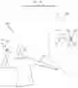
FIG. 1A is a perspective view of a suction dart target game system, according to an embodiment of the invention.
FIG. 1B is a perspective view of a suction dart target game system, with an alternate location of a target marker, according to an embodiment of the invention.
FIG. 1C is a perspective view of a suction dart target game system, illustrating the rotational movement of a throwing member, according to an embodiment of the invention.
FIG. 1D is a perspective view of a suction dart target game system, illustrating the rotational movement of a throwing member, according to an embodiment of the invention.
FIG. 1E is a perspective view of a suction dart target game system, illustrating the rotational movement of a throwing member, according to an embodiment of the invention.
FIG. 1F is a perspective view of a suction dart target game system, illustrating the rotational movement of a throwing member, according to an embodiment of the invention.
FIG. 2A is a top view of a throwing member of a suction dart target game system, according to an embodiment of the invention.
FIG. 2B is a top left view of a throwing member of a suction dart target game system, according to an embodiment of the invention.
FIG. 2C is a top right view of a throwing member of a suction dart target game system, according to an embodiment of the invention.
FIG. 3A is a perspective view of a target marker of a suction dart target game system, according to an embodiment of the invention.
FIG. 3B is a top left view of a target marker of a suction dart target game system, according to an embodiment of the invention.
FIG. 3C is a top right view of a target marker of a suction dart target game system, according to an embodiment of the invention.
FIG. 4A is a front perspective view of a target marker of a suction dart target game system, according to an embodiment of the invention.
FIG. 4B is a rear perspective view of a target marker of a suction dart target game system, according to an embodiment of the invention.
FIG. 5A is a front perspective view of a target marker of a suction dart target game system, according to an embodiment of the invention.
FIG. 5B is a rear perspective view of a target marker of a suction dart target game system, according to an embodiment of the invention.
FIG. 6 is a flowchart illustrating steps that may be followed, in accordance with one embodiment of a suction dart target game method or process.
FIG. 7 is a flowchart illustrating steps that may be followed, in accordance with one embodiment of a suction dart target game method or process.
DETAILED DESCRIPTION
Before describing the invention in detail, it should be observed that the present invention resides primarily in a novel and non-obvious combination of elements and process steps. So as not to obscure the disclosure with details that will readily be apparent to those skilled in the art, certain conventional elements and steps have been presented with lesser detail, while the drawings and specification describe in greater detail other elements and steps pertinent to understanding the invention.
The following embodiments are not intended to define limits as to the structure or method of the invention, but only to provide exemplary constructions. The embodiments are permissive rather than mandatory and illustrative rather than exhaustive.
In the following, we describe the structure of an embodiment of a system for a suction dart target game system 100 with reference to FIG. 1A, in such manner that like reference numerals refer to like components throughout; a convention that we shall employ for the remainder of this specification.
In an embodiment, as shown in FIGS. 1A, 1B, 1C, 1D, 1E, 1F, and 2A, a suction dart target game system 100 can include:
-
- a) at least one throwing member 110, as shown in FIG. 1A, which can include a plurality of throwing members 110, wherein each throwing member 110 can include:
- i. a throwing body 213, as shown in FIG. 2A; and
- ii. a first suction cup 112, as shown in FIG. 1A, which can be mounted on a first end of the throwing body 213, such that an outer end of the first suction cup 112 faces away from the throwing body 213; and
- iii. a second suction cup 114, as shown in FIG. 1A, which can be mounted on a second end of the throwing member 110, such that an outer end of the second suction cup faces away from the throwing body 213; and
- b) a target marker 120, as shown in FIGS. 1A, 3A, 3B, 3C, 4A-4B, and 5A-5B, which can include:
- i. a target body 124; and
- ii. a target suction cup 122, such that an outer end of the target suction cup is connected to an inner end of the target body, such that an outer end of the target body faces away from the target suction cup;
- such that the target suction cup 122 is configured to attach the target marker 120 securely and detachably to a mounting structure 180; and
- whereby the throwing member 110 can be configured to enable a user 190 to throw the throwing member 110 at the target marker 120 from a distance 170, such that the throwing member 110 rotates in flight, as shown in FIGS. 1C, 1D, 1E, and 1F, such that either the first suction cup 112 or the second suction cup 114 attaches to a surface area 182 of the mounting structure 180 adjacent to the target marker 120, if a throw is successful.
- a) at least one throwing member 110, as shown in FIG. 1A, which can include a plurality of throwing members 110, wherein each throwing member 110 can include:
In a related embodiment, the throwing member 110 can be configured to solely include two suction cups mounted on the first end of the throwing body 213 and the second end of the throwing body 213, respectively, i.e. on opposing ends of the throwing body 213.
In another related embodiment, as shown in FIGS. 3A, 3B, and 3C, the target body 124 can be a plate or disk, such that an outer surface 326 of the target body 124 is perpendicular to an elongated axis 328 of the target marker 120. The disk-shaped target body 124 can be circular as shown. In a related embodiment, the throwing member 110 can land on a top of the target marker 120, on the outer surface 326, such that the throwing member 110 suctions to the target marker 120, and thereby attaches to the target marker 120. A diameter (or in general an surface area size) of the outer surface 326 of the target body 124 can be larger than a diameter/surface area size of an outer surface 215 of an attaching suction cup 112, 114 of the throwing member 110, such that the suction cup 112, 114 can be configured to attach to the outer surface 326, such that the throwing member 110 can be capable of landing on the target marker 120.
In yet another related embodiment, as shown in FIGS. 4A and 4B, the target body 424 can be a plate or disk, such that main opposing surfaces 426, 427 of the target body 124 are parallel to an elongated axis 428 of the target marker 420. The plate-shaped target body 424 can be rectangular, for example shaped as an elongated octagon, as shown. Optionally, at least one of the main opposing surfaces 426, 427 can further include a logo indentation 429 for depicting a logo, which for example can be embossed, engraved, or printed.
In another related embodiment, as shown in FIGS. 5A and 5B, the target body 524 can be elongated and rotationally symmetrical around an elongated axis 528 of the target marker 520. The elongated and rotationally symmetric target body 524 can be substantially football-shaped, as shown. Optionally, the target body 524 can further include a logo indentation 529 for depicting a logo, which for example can be embossed, engraved, or printed.
In various further related embodiments, the throwing member 110 and target suction cup 122, can facilitate use for a multitude of different applications, such that the throwing member 110 and target suction cup 122 can be configured to be able to stick and hold to any surface that is not porous.
In a related embodiment, as shown in FIG. 2A, the throwing body 213 can further include:
-
- a) a first stem portion 222, such that an outer end of the first stem portion 222 is connected to an inner end of the first suction cup 112;
- b) a second stem portion 224, such that an outer end of the second stem portion 224 is connected to an inner end of the second suction cup 114; and
- c) a central protrusion 210, which can be configured to protrude from a center portion of the throwing body 213, such that the central protrusion 210 is connected between inner ends of the first stem portion 222 and the second stem portion 224;
- wherein the central protrusion 210 diameter can be 20-50% smaller in diameter than the first suction cup 112 and the second suction cup 114. When the throwing member 110 is molded in one piece, there can be a gradual transition from a suction cup 112, 114 to a corresponding stem portion 222, 224.
In various further related embodiments, the central protrusion 210 of the throwing member 110, along with the narrow stems extending outward, give the throwing piece a comfortable, natural feel in the user's hand when held and thrown. The additional mass of the central protrusion 210 is at the center of the throwing member 110, such that this additional mass gives the piece a central point of gravity when thrown end-over-end; and has very little effect on the rotational inertia of the throwing member 110. This means that, given a “standard throw”, the throwing member 110 will spin at a similar rate as if the additional central mass were not present. Conversely, the additional mass added farther toward the ends of the stems at the suction cups (farther away from the central protrusion), this will significantly increase the throwing member's 110 rotational inertia. This will mean that the throwing member 110, given the same “standard throw”, will spin at a significantly slower rate than that of a throwing member 110 with a smaller rotational inertia.
In another related embodiment, the stems 222, 224 can be configured with a length from the central protrusion 210 to the base of the suction cup, as well as a diameter of the stem, to allow the perfect balance of flexibility and rigidness. This gives the throwing member 110 an optimal capability to absorb impact; as well as be able to deform into a hit (suctioned) position.
In a related embodiment, as shown in FIG. 2A, the throwing member can further include:
-
- a) a first handle portion 212, as shown in FIG. 2A, which can be positioned between an outer end of the first suction cup 112 and a center 230 of the throwing body 213, or between an outer end of the first suction cup 112 and the central protrusion 210; and
- wherein the first handle portion 212 can be configured to gradually narrow towards an inner end of the first handle portion 212;
- whereby the inner end of the first handle portion 212 can be configured to connect with the central protrusion 210;
- b) a second handle portion 214, as shown in FIG. 2A, which can be positioned between an outer end of the second suction cup 114 and a center 230 of the throwing body 213, or between an outer end of the second suction cup 114 and the central protrusion 210; and
- wherein the second handle portion 214 can be configured to gradually narrow towards an inner end of the second handle portion 214;
- whereby the inner end of the second handle portion 214 can be configured to connect with the central protrusion 210. As shown, the handle portions 212, 214 may overlap inner parts of the respective suction cups 112, 114 and outer parts of the respective stems 222, 224.
In another related embodiment, the first handle portion 212 and the second handle portion 214 can be configured with a ribbed surface texture, such that the ribbed surface texture provides an improved grip when holding, throwing or removing the throwing member 110.
In a related embodiment, as shown in FIG. 2A, the throwing member 110 can include:
-
- a) a first outer portion 202, as shown in FIG. 2A, that can include the first suction cup 112 and the first stem portion 222;
- b) a second outer portion 204, as shown in FIG. 2A, that can include the second suction cup 114 and the second stem portion 224;
- c) a center portion 203, between the first outer portion 202 and the second outer portion 204, wherein the center portion 203 comprises the central protrusion 210;
- wherein the first outer portion 202, the center portion 203 and the second outer portion 204 can each be configured to hold approximately one-third of the weight of the throwing member 110;
- wherein the first outer portion 202 and the second outer portion 204 can each weigh approximately 7.3 grams;
- and the center portion 203 can weigh approximately 9.3 grams;
- such that the throwing member 110 can be configured to be able to be evenly end-over-end rotated.
In a further related embodiment, a weight of the center portion 203, i.e. a central weight of the central protrusion 210 can be in a range of 35%-43% of a total weight of the throwing member 110.
In a related embodiment, the throwing member 110 and the target marker 120 can each be molded from a resilient material, such as a synthetic or natural rubber material, including a soft silicone rubber. The throwing member 110 can be made from a soft resilient material, such that a suction cup 112 emits a “popping” sound when landing and sticking to a surface. the throwing member 110 and the target marker 120 can each be molded in one piece.
In an embodiment, rules for playing the suction dart target game by using the suction dart target game system 100, can include:
-
- a) The game is played with six suction darts 110 (also called throwing members 110) and one target marker 120. There are three suction darts 110 per team and they are made of a different color to distinguish between teams. The game is played with two opponents, with each player (team) having three suction darts 110;
- b) A game begins with the toss of a coin. The team that wins the coin toss can choose to either have first target placement or choice of suction dart 110 color. To start a game, the target marker 120 is placed by the player determined at the coin toss. A player can put the target marker 120 on any vertical or horizontal surface that it can be suctioned to and at any distance;
- c) The player placing the target marker 120 can give custom parameters for that one round. The player can make the parameters as easy or as difficult as they choose. Parameters can include, but are not limited to the following:
- i. The type of throw: Underhand, overhand, side arm, behind the back;
- ii. Distance: 6 feet, 10 feet, etc. or may use terms like, “Behind here”
- d) Once the parameters are set, the player that placed the target marker 120 throws the first suction dart 110. The players rotate throwing their suction darts 110 to get closest to the target marker 120. This continues until both players have thrown all their suction darts 110. After both players have exhausted all their suction darts 110, the round is over and points are awarded;
- e) Any suction dart 110 that does not suction to the surface is considered a dead dart and is left in play until the end of a round;
- f) At the end of each round, points will be awarded. Only one player scores in a round;
- g) One point is awarded for each suction dart 110 that is closer to the target marker 120 than the closest suction dart 110 of the opposing player;
- h) If one of the closest player's suction darts 110 are touching the target marker 120, the suction dart 110 will count as 2 points;
- i) If the suction dart 110 lands on top of and suctions to the target marker 120, the player is awarded 3 points and automatically wins that round;
- j) The player that was awarded points in the previous round begins the next round by selecting the next target marker 120 location;
- k) In the event that the closest suction dart 110 of each player is the same distance from the target marker 120, no points will be awarded and the target marker returns to the player that delivered it. All measurements should be made from the close edge of the suction dart to the close edge of a target marker;
- l) Games are played to 12 points, with the first team reaching 12 points being the winner of a game.
In an embodiment, as illustrated in FIG. 6, a method for a suction dart target game 600, can include:
-
- a) Selecting location 602, wherein the user 190 attaches the target marker to a mounting structure 180;
- b) Receiving throwing members 604, wherein the first user 190 receives a plurality of throwing members 110;
- c) A second user 190 receiving throwing members 606, wherein the second user 190 receives a plurality of throwing members 110;
- d) Throwing members at board 608, wherein the first user 190 and the second user 190 throw all of their plurality of the throwing member 110 at the target marker 120;
- e) The user 190 recording the location 610, wherein the first user 190 can record the distance of their plurality of the throwing member 110 from the target marker 120;
- f) The second user 190 recording the location 612, wherein the second user 190 can record the distance of their plurality of the throwing member 110 from the target marker 120;
- g) Allocating points 614, wherein the first user 190 and second user 190 can allocate points based on the distance of the throwing member to the target marker 120;
- such that the first user 190 or the second user 190 with the throwing member(s) 110 with the closest distance of the throwing member(s) 110 to the target marker 120 receives a point;
- whereby in a case that the first user 190 or the second user 190 with the throwing member 110 with the closest distance of the throwing member 110 to the target marker 120 has the throwing member 110 touching the target marker 120, an additional point will be awarded;
- whereby in a secondary case that the first user 190 or the second user 190 with the throwing member 110 with the closest distance of the throwing member 110 to the target marker 120 has the throwing member 110 landing atop of and suctioning to the target marker 120, a total of three points will be awarded;
- such that for every round, only the first user 190 or the second user 190 can obtain points; and
- h) Reobtaining throwing members 616, wherein the first user 190 and the second user 190 can reobtain their thrown plurality of throwing member(s);
- i) Replaying until receiving full score points 618, wherein a full score can be twelve points, wherein the first user 190 and the second user 190 can rethrow their respective plurality of the throwing member 110 at the target wherein either the first user 190 or the second user 190, respectively, wins the game, wherein the game can be concluded.
In a further related embodiment of the method for a suction dart and target recreational game 400, six of the throwing members 110 for use in the method for a suction dart and target recreational game 400 can be configured such that three out of the six of the throwing member 110 can be made of a designated color and the remaining three of the six of the throwing member 110 can be made of a different designated color; such that the first user 190 and the second user 190 can differentiate ownership of the throwing member 110;
In an embodiment, as illustrated in FIG. 7, a method for a suction dart target game 700, can include:
-
- a) positioning 702 a target marker, wherein a user attaches the target marker to a mounting structure;
- b) throwing 704 a throwing member, wherein the user throws the throwing member towards the target marker from a throwing distance 170, such that the throwing member rotates in flight, such that either a first suction cup or a second suction cup of the throwing member attaches to a surface area 182 of the mounting structure adjacent to the target marker; and
- c) measuring 706 a target distance 160 from the throwing member to the target marker, when the throwing member is attached to the portion of the mounting structure adjacent to the target marker.
In a related embodiment of the suction dart target game method, the target marker can be positioned on a vertical surface of the mounting structure, as shown in FIG. 1A.
In another related embodiment of the suction dart target game method, the target marker can be positioned on a horizontal surface of the mounting structure, as shown in FIG. 1B.
In an embodiment, the throwing member 110 can be thrown at the target marker 120, wherein the target marker 120 can be positioned vertically or horizontally, the throwing member 110 can include the central protrusion 210 to allow for even end-over-end rotation, the first handle portion 212 and second handle portion 214, can be just long enough to allow flexibility upon impact, wherein the first handle portion 212 and second handle portion 214 start to widen near the opposing ends displacing the weight farther from the central protrusion 210 to allow the throwing member 110 to have a slower and more controlled rotation through the air, wherein the first suction cup 112 and the second suction cup 114 are designed to be able to stick and hold to any flat (horizontal and vertical) surface that is not porous.
Here has thus been described a multitude of embodiments of the suction dart target game system 100, and methods related thereto, which can be employed in numerous modes of usage.
The many features and advantages of the invention are apparent from the detailed specification, and thus, it is intended by the appended claims to cover all such features and advantages of the invention, which fall within the true spirit and scope of the invention.
Many such alternative configurations are readily apparent and should be considered fully included in this specification and the claims appended hereto. Accordingly, since numerous modifications and variations will readily occur to those skilled in the art, the invention is not limited to the exact construction and operation illustrated and described, and thus, all suitable modifications and equivalents may be resorted to, falling within the scope of the invention.
Claims
What is claimed is:1. A suction dart target game system, comprising:
a) at least one throwing member, comprising:
a throwing body;
a first suction cup, which is mounted on a first end of the throwing body, such that an outer end of the first suction cup faces away from the throwing body; and
a second suction cup, which is mounted on a second end of the throwing body, such that an outer end of the second suction cup faces away from the throwing body; and
b) a target marker, comprising:
a target body; and
a target suction cup, such that an outer end of the target suction cup is connected to an inner end of the target body, such that an outer end of the target body faces away from the target suction cup;
wherein the target suction cup is configured to detachably attach to a mounting structure; and
whereby the at least one throwing member is configured to enable a user to throw the at least one throwing member at the target marker from a distance, such that the at least one throwing member rotates in flight, such that either the first suction cup or the second suction cup attaches to a surface area of the mounting structure adjacent to the target marker, if a throw is successful.
2. The suction dart target game system of claim 1, wherein the at least one throwing member comprises solely two suction cups mounted on opposing ends of the throwing body.
3. The suction dart target game system of claim 1, wherein the target body is configured as a plate, such that an outer surface of the target body is perpendicular to an elongated axis of the target marker.
4. The suction dart target game system of claim 3, wherein a surface area size of the outer surface of the target body is larger than a surface area size of an outer surface of an attaching suction cup of the at least one throwing member, such that the attaching suction cup is configured to attach to the outer surface of the target body, such that the at least one throwing member is capable of landing on the target marker.
5. The suction dart target game system of claim 1, wherein the target body is configured as a plate, such that main opposing surfaces of the target body are parallel to an elongated axis of the target marker.
6. The suction dart target game system of claim 1, wherein the target body is elongated and rotationally symmetrical around an elongated axis of the target marker.
7. The suction dart target game system of claim 1, wherein the at least one throwing member further comprises:
a central protrusion which is configured to protrude from a center portion of the throwing body.
8. The suction dart target game system of claim 7, wherein a weight of the central protrusion is in a range of 35%-43% of a total weight of the at least one throwing member.
9. The suction dart target game system of claim 7, wherein the at least one throwing member further comprises:
a first stem portion, such that an outer end of the first stem portion is connected to an inner end of the first suction cup; and
a second stem portion, such that an outer end of the second stem portion is connected to an inner end of the second suction cup;
such that the central protrusion is connected between the first stem portion and the second stem portion.
10. The suction dart target game system of claim 1, wherein the at least one throwing member further comprises:
a first handle portion, which is positioned between an outer end of the first suction cup and a center of the throwing body; and
a second handle portion, which is positioned between an outer end of the second suction cup and the center of the throwing body.
11. The suction dart target game system of claim 10, wherein the first handle portion and the second handle portion are each configured with a ribbed surface texture.
12. A suction dart target game method, comprising:
positioning a target marker, wherein a user attaches the target marker to a mounting structure; and
throwing a throwing member, wherein the user throws the throwing member towards the target marker from a throwing distance, such that the throwing member rotates in flight, such that either a first suction cup or a second suction cup of the throwing member attaches to a surface area of the mounting structure adjacent to the target marker.
13. The suction dart target game method of claim 12, further comprising:
measuring a target distance from the throwing member to the target marker, when the throwing member is attached to the surface area of the mounting structure adjacent to the target marker.
14. The suction dart target game method of claim 12, wherein the target marker is positioned on a vertical surface of the mounting structure.
15. The suction dart target game method of claim 12, wherein the target marker is positioned on a horizontal surface of the mounting structure.
16. The suction dart target game method of claim 12,
wherein the throwing member comprises:
a throwing body;
the first suction cup, which is mounted on a first end of the throwing body, such that an outer end of the first suction cup faces away from the throwing body; and
the second suction cup, which is mounted on a second end of the throwing body, such that an outer end of the second suction cup faces away from the throwing body; and
wherein the target marker comprises:
a target body; and
a target suction cup, such that an outer end of the target suction cup is connected to an inner end of the target body, such that an outer end of the target body faces away from the target suction cup;
wherein the target suction cup is configured to detachably attach to the mounting structure.
17. The suction dart target game method of claim 16, wherein the throwing member further comprises:
a central protrusion which is configured to protrude from a center portion of the throwing body.
18. The suction dart target game method of claim 17, wherein the throwing member further comprises:
a first stem portion, such that an outer end of the first stem portion is connected to an inner end of the first suction cup; and
a second stem portion, such that an outer end of the second stem portion is connected to an inner end of the second suction cup;
such that the central protrusion is connected between the first stem portion and the second stem portion.
19. The suction dart target game method of claim 16, wherein the throwing member further comprises:
a first handle portion, which is positioned between an outer end of the first suction cup and a center of the throwing body; and
a second handle portion, which is positioned between an outer end of the second suction cup and the center of the throwing body.
20. The suction dart target game method of claim 19, wherein the first handle portion and the second handle portion are each configured with a ribbed surface texture.
Images & Drawings included:


Sources:
- United States Patent and Trademark Office - verify current appl. status at the USPTO↗
Similar patent applications:
- » 20230003492
Suction dart target game system and method
Recent applications in this class:
- » 20250155229 2025-05-15
BROADHEAD - » 20250093136 2025-03-20
Jacketed Archery Arrow Insert System for Arrows - » 20250093135 2025-03-20
ARROW TIP - » 20250060201 2025-02-20
EXPANDABLE BROADHEAD FOR ARROW - » 20250052549 2025-02-13
Rear Deploying Broadhead - » 20250052548 2025-02-13
Variable cutting diameter arrowhead - » 20250044065 2025-02-06
ARROWS AND BROADHEADS - » 20250035414 2025-01-30
Multi-Functional Broadhead Fixed and Mechanical - » 20250027756 2025-01-23
ADJUSTABLE OUTSERT SYSTEM - » 20240337472 2024-10-10
BROADHEAD