Slide valve of a single screw compressor
US20220136506A1
2022-05-05
17/431,709
2020-02-20
✅ Patent granted
US 12,158,147 B2
2024-12-03
WO; PCT/GB2020/050405; 20200220
WO; WO2020/169978; 20200827
Mary A Davis
Rahman LLC
2040-02-20
Abstract:
A single screw compressor comprises a main rotor and at least one gate rotor, a casing for the main rotor having a discharge port at a discharge end of the casing, and a slide slidable within a bore in the casing adjacent the main rotor. The slide has a cut-out (6) between first (2) and second (4) sealing parts of the slide, the slide is slidable between a high volume ratio position where the cut-out (6) is within the casing and provides a path to the discharge port, and a low volume ratio position where the slide is beyond the discharge end of the casing to provide a fixed discharge path in the bore of the casing.
Inventors:
- Terence William Thomas Young 5 🇬🇧 Gravesend, United Kingdom
- John Michael Roll 3 🇬🇧 Fawkham, United Kingdom
- Maghmood Van Der Poll 1 🇬🇧 Erith, United Kingdom
Assignee:
- DAIKIN INDUSTRIES, LTD. 3,627 🇯🇵 Osaka, Japan
- J & E Hall Limited 1 🇬🇧 Dartford, United Kingdom
Applicant:
Interested in similar patents?
Get notified when new applications in this technology area are published.
Classification:
F04C3/085 » CPC further
Rotary-piston machines or pumps, with non-parallel axes of movement of co-operating members, e.g. of screw type the axes being arranged otherwise than at an angle of 90 degrees of intermeshing engagement type, i.e. with engagement of co-operating members similar to that of toothed gearing the axes of cooperating members being on the same plane
F04C3/08 IPC
Rotary-piston machines or pumps, with non-parallel axes of movement of co-operating members, e.g. of screw type the axes being arranged otherwise than at an angle of 90 degrees of intermeshing engagement type, i.e. with engagement of co-operating members similar to that of toothed gearing
F04C28/12 » CPC further
Control of, monitoring of, or safety arrangements for, pumps or pumping installations specially adapted for elastic fluids characterised by changing the positions of the inlet or outlet openings with respect to the working chamber using sliding valves
F04C18/52 » CPC main
Rotary-piston pumps specially adapted for elastic fluids; Rotary-piston pumps with non-parallel axes of movement of co-operating members the axes being arranged at an angle of 90 degrees of intermeshing engagement type, i.e. with engagement of co-operating members similar to that of toothed gearing
Description
BACKGROUND TO THE INVENTION
This invention relates to a single screw compressor with a variable volume ratio (VR).
Screw compressors traditionally use slides to control the capacity of the compressor and/or the volume ratio of the compression process.
Capacity control slides, such as that shown in FIG. 1, conventionally operate in the axial plane along the rotor(s). The suction end of the slides delays the start of compression by opening a bypass port during the early rotation period of the main rotor, thereby effectively reducing the swept volume (capacity) of the compressor. At the same time the delivery port opening is delayed, thus maintaining approximately constant VR during most of the compression process.
Variable frequency drives are now commonly used to provide capacity control of screw compressors. However the slides are retained to provide a variable volume ratio function.
As operating conditions change, the required built in volume ratio needs to change to match these changing conditions, if optimum efficiency is to be achieved. An example of a variable volume ratio slide is shown in FIG. 2. This can be considered as a modification of the conventional capacity control slide. This is achieved by extending the suction end of the slide such that no bypass port to suction is opened during the full axial movement of the slide. The slide VR port is then designed to provide the varying volume ratio as the rotor flute opens to the discharge port via the slide VR port.
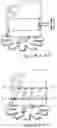
The conventional VVR slide has the disadvantage that it must extend from the discharge port to the end of the rotor such that even when the slide is at the highest VR position (travel towards the discharge end of the rotor) the suction end of the rotor is sealed and no bypassing to suction can occur. This slide must have clearance in the slide bore if it is to move freely. This clearance provides a leakage path directly from discharge to suction and to a lesser extent intermediate pressure also sealed by the slide can leak to suction. This leakage occurs when the slide is at any position and results in an unwanted reduction in compressor efficiency. FIG. 3 schematically shows the slide in place in the compressor and FIG. 4 shows the slide leakage paths 1.
SUMMARY OF THE INVENTION
It is an aim of the invention to eliminate this leakage path from discharge to suction and thereby to improve the base efficiency.
The invention employs a simple two step arrangement, which can match the efficiency of a true fully modulating variable VR slide due to the reduced leakage effect.
The present invention provides a single screw compressor comprising a main rotor and at least one gate rotor, a casing for the main rotor having a discharge port at a discharge end of the casing, and a slide slidable within a bore in the casing adjacent the main rotor, the slide having a cut-out between first and second sealing parts of the slide, the slide being slidable between a high volume ratio position where the cut-out is within the casing and provides a path to the discharge port, and a low volume ratio position where the slide is beyond the discharge end of the casing to provide a fixed discharge path in the bore of the casing.
In one embodiment, the first, i.e. upstream, sealing part of the rotor, has a surface facing away from the cut-out that is substantially in a plane transverse to the axes of the slide and the main rotor. This is for ease of manufacture.
In an alternative embodiment, the first, sealing part of the rotor, has a surface facing away from the cut-out that is inclined to a plane transverse to the axes of the slide and the main rotor at an angle substantially the same as the main rotor pitch angle. This gives accurate VR control.
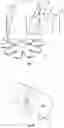
BRIEF DESCRIPTION OF THE DRAWINGS
The invention will now be described in more detail, by way of example only, with reference to the accompanying drawings, in which;
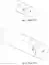
FIG. 1 shows the known capacity control slide discussed above;
FIG. 2 shows the known VR control slide discussed above;
FIGS. 3 and 4 are views showing the known VR control slide and its leakage paths;
FIG. 5 shows a slide according to an embodiment of the invention;
FIGS. 6 and 7 show the slide of FIG. 5 at different positions in the compressor;
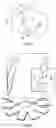
FIG. 8 shown a slide according to an alternative embodiment; and
FIGS. 9 and 10 show the slide of FIG. 5 at different positions in the compressor.
DETAILED DESCRIPTION OF PARTICULAR EMBODIMENTS
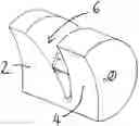
FIG. 5 shows a slide according to the invention having sealing parts 2, 4 and a cut-out 6.
FIG. 6 shows the slide of FIG. 5 positioned in towards the main casing alongside the main rotor. The cut-out 6 provides an accurate high VR discharge port.
FIG. 7 shows how a lower VR is achieved. The slide is pulled out from the casing so that it is beyond the main rotor and thus the VR is formed from the port 8 remaining in the casing.
The slide of FIGS. 5 to 7 is a simple slide. The higher VR slide discharge port provided by the cut-out 6 correctly aligns with the rotor flute, but when the slide is withdrawn beyond the rotor the remaining low VR fixed port does not match the true VR requirement.
FIGS. 8 to 10 show an alternative slide which has the same high VR cut-out as the slide of FIGS. 5 to 7. However this slide also has the correct low VR remaining in the casing when the slide is moved out of engagement beyond the rotor as shown in FIG. 10.
The simple slide of FIGS. 5 to 7 is easier to produce and the VR compromise is less detrimental at the Low VR operating conditions than at higher VR conditions. The true VR slide of FIGS. 8 to 10 will provide the highest efficiency.
Claims
1. A single screw compressor comprising a main rotor and at least one gate rotor, a casing for the main rotor having a discharge port at a discharge end of the casing, and a slide slidable within a bore in the casing adjacent the main rotor, the slide having a cut-out between first and second sealing parts of the slide, the slide being slidable between a high volume ratio position where the cut-out is within the casing and provides a path to the discharge port, and a low volume ratio position where the slide is beyond the discharge end of the casing to provide a fixed discharge path in the bore of the casing.
2. A compressor according to claim 1, wherein the first, i.e. upstream, sealing part of the rotor, has a surface facing away from the cut-out that is substantially in a plane transverse to the axes of the slide and the main rotor.
3. A compressor according to claim 1, wherein the first, i.e. upstream, sealing part of the rotor, has a surface facing away from the cut-out that is inclined to a plane transverse to the axes of the slide and the main rotor at an angle substantially the same as the main rotor pitch angle.
Images & Drawings included:

Sources:
- United States Patent and Trademark Office - verify current appl. status at the USPTO↗
Recent applications in this class:
- » 20220034319 2022-02-03
Screw compressor - » 20210396230 2021-12-23
High suction pressure single screw compressor with thrust balancing load using shaft seal pressure and related methods - » 20210131435 2021-05-06
Screw compressor having slide valve with crescent-shaped valve body and cylindrical guide portion - » 20200032800 2020-01-30
Single-screw compressor with a gap adjuster mechanism - » 20200003212 2020-01-02
Single-screw compressor - » 20190331114 2019-10-31
Bearing for a screw rotor of a screw compressor - » 20190195226 2019-06-27
High suction pressure single screw compressor with thrust balancing load using shaft seal pressure and related methods - » 20180017058 2018-01-18
Screw compressor with an hydropneumatic cylinder integral with the bearing holder - » 20130011291 2013-01-10
Single-screw compressor having an adjustment mechanism for adjusting a compression ratio of the compression chamber - » 20120183418 2012-07-19
Screw compressor having reverse rotation protection
Recent applications for this Assignee:
- » 20250290676 2025-09-18
AIR CONDITIONING UNIT - » 20250289933 2025-09-18
METHOD FOR PRODUCING POLYTETRAFLUOROETHYLENE MICROPOWDER AND POLYTETRAFLUOROETHYLENE POWDER - » 20250286068 2025-09-11
FLUORORESIN FOR BINDER FOR ELECTROCHEMICAL DEVICES, BINDER FOR ELECTROCHEMICAL DEVICES, ELECTRODE MIXTURE, ELECTRODE, AND SECONDARY BATTERY - » 20250283644 2025-09-11
REFRIGERATION CYCLE SYSTEM - » 20250282704 2025-09-11
METHOD FOR PRODUCING FLUOROALKOXIDE - » 20250270727 2025-08-28
ELECTRODEPOSITION COATING COMPOSITION, COATING, COATED ARTICLE, COATED ELECTRIC WIRE AND PRINTED BOARD - » 20250263672 2025-08-21
SYRINGE FOR CRYOPRESERVATION OF CELLS, NUCLEIC ACIDS, OR PROTEINS - » 20250262911 2025-08-21
REFRIGERANT-CONTAINING COMPOSITION, USE OF SAME, REFRIGERATOR COMPRISING SAME, AND METHOD FOR OPERATING REFRIGERATOR - » 20250260063 2025-08-14
ELECTROLYTIC SOLUTION, ELECTROCHEMICAL DEVICE, SECONDARY BATTERY, AND LITHIUM-ION SECONDARY BATTERY - » 20250253408 2025-08-07
ELECTROLYTE SOLUTION, LITHIUM SULFUR SECONDARY BATTERY AND MODULE