METHOD AND APPARATUS FOR GRINDING AND DRYING A MATERIAL OR A MIXTURE OF MATERIALS
US20220143622A1
2022-05-12
17/437,712
2020-03-18
✅ Patent granted
US 12,337,329 B2
2025-06-24
WO; PCT/SE2020/050286; 20200318
WO; WO2020/190202; 20200924
Mohammed S. Alawadi
Blank Rome LLP
2041-08-26
Abstract:
The invention relates to a method for grinding and drying a material or material mixture (M), using a cyclone device (10) which communicates with an outlet line (52) for gas (G) and material (M) processed in the cyclone device (10), wherein at least a portion of the gas (G) and material (M) in the outlet line (52) are returned into a lower opening (14) of the cyclone device (10) for further cyclone treatment. The invention relates also to an apparatus.
Assignee:
- Airgrinder AB 1 🇸🇪 Skelleftehamn, Sweden
Applicant:
Interested in similar patents?
Get notified when new applications in this technology area are published.
Classification:
B02C23/10 » CPC further
Auxiliary methods or auxiliary devices or accessories specially adapted for crushing or disintegrating not provided for in preceding groups or not specially adapted to apparatus covered by a single preceding group; Separating or sorting of material, associated with crushing or disintegrating with separator arranged in discharge path of crushing or disintegrating zone
B02C23/24 » CPC further
Auxiliary methods or auxiliary devices or accessories specially adapted for crushing or disintegrating not provided for in preceding groups or not specially adapted to apparatus covered by a single preceding group; Adding fluid, other than for crushing or disintegrating by fluid energy Passing gas through crushing or disintegrating zone
B02C23/26 » CPC further
Auxiliary methods or auxiliary devices or accessories specially adapted for crushing or disintegrating not provided for in preceding groups or not specially adapted to apparatus covered by a single preceding group; Adding fluid, other than for crushing or disintegrating by fluid energy; Passing gas through crushing or disintegrating zone characterised by point of gas entry or exit or by gas flow path
B02C23/34 » CPC further
Auxiliary methods or auxiliary devices or accessories specially adapted for crushing or disintegrating not provided for in preceding groups or not specially adapted to apparatus covered by a single preceding group; Adding fluid, other than for crushing or disintegrating by fluid energy; Passing gas through crushing or disintegrating zone gas being recirculated to crushing or disintegrating zone
F26B1/005 » CPC further
Preliminary treatment of solid materials or objects to facilitate drying, e.g. mixing or backmixing the materials to be dried with predominantly dry solids by means of disintegrating, e.g. crushing, shredding, milling the materials to be dried
F26B17/107 » CPC further
Machines or apparatus for drying materials in loose, plastic, or fluidised form, e.g. granules, staple fibres, with progressive movement with movement performed by fluid currents, e.g. issuing from a nozzle, e.g. pneumatic, flash, vortex or entrainment dryers pneumatically inducing within the drying enclosure a curved flow path, e.g. circular, spiral, helical; Cyclone or Vortex dryers
B02C19/06 » CPC main
Other disintegrating devices or methods Jet mills
B02C9/00 IPC
Other milling methods or mills specially adapted for grain
B02C19/00 IPC
Other disintegrating devices or methods
B04C9/00 IPC
Combinations with other devices, e.g. fans, expansion chambers, diffusors, water locks
F26B1/00 IPC
Preliminary treatment of solid materials or objects to facilitate drying, e.g. mixing or backmixing the materials to be dried with predominantly dry solids
F26B1/00 IPC
Processes for drying
F26B3/10 IPC
Drying solid materials or objects by processes involving the application of heat by convection, i.e. heat being conveyed from a heat source to the materials or objects to be dried by a gas or vapour, e.g. air the gas or vapour carrying the materials or objects to be dried with it
F26B17/10 IPC
Machines or apparatus for drying materials in loose, plastic, or fluidised form, e.g. granules, staple fibres, with progressive movement with movement performed by fluid currents, e.g. issuing from a nozzle, e.g. pneumatic, flash, vortex or entrainment dryers
F26B21/04 IPC
Arrangements or duct systems, e.g. in combination with pallet boxes, for supplying and controlling air or gases for drying solid materials or objects; Circulating air or gases in closed cycles, e.g. wholly within the drying enclosure partly outside the drying enclosure
F26B21/12 IPC
Arrangements or duct systems, e.g. in combination with pallet boxes, for supplying and controlling air or gases for drying solid materials or objects; Controlling, e.g. regulating, parameters of gas supply Velocity of flow; Quantity of flow, e.g. by varying fan speed, by modifying cross flow area
Description
The present invention relates to a method according to the preamble of claim 1. The invention also relates to an apparatus.
BACKGROUND OF THE INVENTION
In a variety of contexts, there is a great need to grind and dry different materials or mixtures of materials. As a non-limiting example, grinding and drying different types of material can be mentioned.
THE OBJECT OF THE INVENTION
An object of the invention is to provide a method and an apparatus which is very advantageous in grinding and drying various materials/material mixtures. This object is fulfilled by the invention having the features stated in the claims.
THE ADVANTAGES OF THE INVENTION
Among the many advantages of the invention it can be mentioned, inter alia, that extremely good grinding and drying results can be obtained requiring a very low energy consumption.
SHORT DESCRIPTION OF THE DRAWINGS
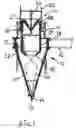
FIG. 1 is a schematic section through a cyclone device which can be used for carrying out the invention,
FIG. 2 is a schematic illustration of the invention,
FIG. 3 shows schematically an inlet for recirculation to the cyclone device.
DETAILED DESCRIPTION OF EMBODIMENTS
FIG. 1 shows a cyclone device 10 which can be used in the method according to the invention. It has a housing with a cylindrical portion 11 having a tangential inlet from an inlet line 12, and the cylindrical portion transforms into a conical portion 13 having a bottom outlet 14. A vortex collector in the form of a cylindrical tube 15 which can have a conical end 16 extends downwardly through a lid 17 of the cylindrical portion and act as an outlet to the atmosphere, for example. The axial position of the vortex collector may be set as indicated by the adjusting means 18, 19 which may be remote operable. A restriction for the outlet 52 is formed by a cone 20 so that an annular outlet slot 21 is formed, and this slot can be adjusted with a set screw 22 which is suitably remotely operable.
When air or other gas is blown by a fan, not shown, into the inlet line 12, a downward vortex is formed which then turns and forms a central ascending vortex which is trapped by the vortex collector. The dash dotted lines 30 indicate the boundary between overpressure on the outside and negative pressure on the inside of the lines.
The cyclone device 10 has a bottom outlet 14, wherein a material supplied together with the supply air (gas) in the inlet line 12 settles on the conical wall and travels downwardly along the wall and out through the outlet 14. As can be seen in the figure by the dash dotted lines 30, there is overpressure along the conical wall but negative pressure in the center of the outlet so that ambient air flows in, as indicated by the arrow 32. The cyclone device 10 and its properties are not described in detail since a cyclone device of this type is described in closer detail in U.S. Pat. No. 5,236,132. Reference is made to this document.
FIG. 2 shows schematically an illustration of an inventive arrangement.
A fan device 50 is provided at a free end portion of the inlet line 12 connected to the cyclone device 10. The fan device 50 is preferably adjustable in terms of blow capacity for adaptation to various modes of operation.
Between the fan device 50 and the cyclone device 10, a device 40 for variable input of a material M or material mixture is arranged.
Sometimes it may be convenient to arrange a valve (not shown) in the inlet line 12 to effect the flow rate, if necessary.
After the operating cycle in the cyclone device 10, air/gas G and grinded material/material mixture M exit through the adjustable restriction valve 54 and further into an outlet line 52 which leads to an end station 61 for transporting away grinded products, gas evacuation and liquid evacuation, etc. Recovery of thermal energy is also possible.
It should be mentioned that a certain amount of grinded material normally leaves the cyclone device 10 through its opening 14. This is normally not desirable due to, inter alia, disruption in logistics operations.
According to the present invention, a return feed line 72 is provided between the outlet line 52 and the opening 14 of the cyclone device 10. In the return feed line 72, a preferably remote-controlled valve 75 is provided for controlling gas and material flow upon return feed to the opening 14 of the cyclone device 10 which is now converted to a return feed inlet 80. The return feed line 72 is connected to the outlet line 52 after the valve 54, in view of the flow through said line. The arrows 90, 91, 92 show flow directions.
FIG. 3 shows an example of how a connection of the return feed line 72 to the lower opening 14 of the cyclone device 10, which now becomes a return feed inlet 80, can be formed. The end portion 73 of the return feed line is adapted regarding its design and size for intended cooperation with the opening 14 so that optimum interaction exists with the cyclone device 10. It is also possible to arrange vortex-forming means in connection with the end portion 73 of the return feed line.
It is also possible to design the connection of the return feed line to the lower end of the cyclone device so that a certain material discharge is still possible, if appropriate.
The inventive return feed line 72 enables a very advantageous recycling of gas and material/material mixtures to the bottom region of the cyclone device, which provides for a significant quality increase and energy saving as well as increased drying effect. The valve or valve assembly 75 in the return feed line may be closed when no recirculation is present and exhibit varying degree of opening depending on the desired degree of return.
It should be understood that the entire aforementioned process can be automated by providing a plurality of sensors/transducers or the like at appropriate locations. In that connection, the fan 50, the material supply device 40, and the valves 54 and 75, for example, can be controlled for optimal cooperation. It is also possible to provide a remote-controlled valve assembly 75 in line 52 after the inlet of the return feed line 72, in view of the flow through said line, for further control of the return amount, etc.
Thus, it will be understood that the valve assembly 75 can be remote controlled in a variety of ways. For example, the valve assembly 75 may comprise one or more actuators or control means (not shown) arranged to control the degree of opening or closing of valve assembly 75. Said actuators or control means can in turn be controlled remote by a control a device or a controller (not shown), for example, which is arranged to control valve assembly 75 directly or via said actuators or control means. The control can be done by wireless or wired electronic communication using appropriate communication protocols, or mechanical control arrangements, or other suitable control means and/or control devices.
The remote control of valve assembly 75 may be done so that valve assembly 75 is controlled from fully closed to fully open, or vice versa, depending on measurement results from the content of outlet line 52. Thus, the control device may be arranged to control the valve assembly 75 based on one or more measurement results, for example.
Said measurement results can be provided directly or indirectly to the control device by one or more sensors/transducers.
Furthermore, the valve assembly 75 may be arranged to be remote controlled completely steplessly/continuously or in discrete positions. This can be done from fully closed position/location to fully open position/location, or vice versa.
Possible preheating of the inlet gas G is of course possible, if desired, as well as functionally equivalent choice of components.
It is also convenient to provide equipment for controlling the system pressure of the gas G.
It should be understood that all process control is preferably automated by e.g. provision of required sensors and control means, etc.
The invention can, of course, be varied by replacement of functionally equivalent components.
Thus, the invention is not limited to what is shown and described, instead changes and modifications are, of course, possible within the scope of protection of the appended claims.
Claims
1. A method for grinding and drying a material or a mixture of materials, using a cyclone device communicating with an outlet line for gas and material processed in the cyclone device, wherein at least a portion of the gas and the material in the outlet line is returned into a lower opening of the cyclone device for further cyclone treatment.
2. The method according to claim 1, wherein the return of said at least a portion of the gas and the material is made via a return feed line extending between the outlet line and the lower opening of the cyclone device, and the desired rate of return feed is controlled by a valve assembly arranged in the return feed line.
3. The method according to claim 1, wherein the main supply to the cyclone device of gas and material takes place via a supply line which discharges into an upper region of the cyclone device.
4. The method according to claim 2, wherein the valve assembly is remote controlled.
5. The method according to claim 4, wherein the valve assembly is remote controlled from fully closed to fully open, or vice versa, depending on measurement results from the contents of the outlet line.
6. The method according to claim 5, wherein the valve assembly is steplessly remote controlled or remote adjustable in discrete positions.
7. Apparatus for grinding and drying a material or material mixture, the apparatus comprising a cyclone device communicating with an outlet line for gas and material, wherein a return feed line is arranged between the outlet conduit and a lower opening of the cyclone device.
8. The apparatus according to claim 7, wherein a valve assembly is arranged in the return feed line.
9. The apparatus according to claim 7, wherein an end portion of the return feed line projects through the lower opening of the cyclone device.
10. The apparatus according to claim 9, wherein a vortex-forming means is arranged at the end portion of the return feed line.
11. The apparatus according to claim 7, wherein the valve assembly is remote controlled.
12. The apparatus according to claim 11, wherein the valve assembly is remote controlled from fully closed to fully open, or vice versa, depending on measurement results from the contents of the outlet conduit.
13. The apparatus according to claim 12, wherein the valve assembly is steplessly remote controlled or remote adjustable in discrete positions.
Images & Drawings included:


Sources:
- United States Patent and Trademark Office - verify current appl. status at the USPTO↗
Recent applications in this class:
- » 20250099970 2025-03-27
JET MILL SYSTEM WITH IMPROVED PULVERIZATION EFFICIENCY - » 20240226911 2024-07-11
JET MILL DEVICE - » 20240226910 2024-07-11
A System and a Method for Micronization of Solid Particles using Valvular Conduit - » 20230405600 2023-12-21
AN AERO ACOUSTIC PROCESSING APPARATUS AND PROCESS FOR PROCESSING WASTE - » 20220362781 2022-11-17
APPARATUS TO RECOVER INCOHERENT MATERIAL PRESENT IN A PROCESS FLUID, AND CORRESPONDING METHOD - » 20200156081 2020-05-21
Powder grinding method and powder grinding machine - » 20190291118 2019-09-26
Apparatus for the micronization of powdered material with the capacity to prevent incrustations - » 20190262839 2019-08-29
Milling oilfield particulates - » 20180304273 2018-10-25
Counter-impact jet milling mechanism and jet mill using the same - » 20180214888 2018-08-02
APPARATUS FOR EXFOLIATING PLATE-SHAPED MATERIAL COMPRISING MICROCHANNEL