ATOMIZER
US20220160035A1
2022-05-26
17/233,520
2021-04-18
Abstract:
An atomizer includes a glass tube and a cartridge. The cartridge is disposed in the glass tube. The cartridge includes a side wall including an air outlet; and the lower end of the side wall includes an air inlet.
Interested in similar patents?
Get notified when new applications in this technology area are published.
Classification:
A24F40/42 » CPC main
Electrically operated smoking devices; Component parts thereof; Manufacture thereof; Maintenance or testing thereof; Charging means specially adapted therefor; Constructional details, e.g. connection of cartridges and battery parts Cartridges or containers for inhalable precursors
A24F40/10 » CPC further
Electrically operated smoking devices; Component parts thereof; Manufacture thereof; Maintenance or testing thereof; Charging means specially adapted therefor Devices using liquid inhalable precursors
A24F40/46 » CPC further
Electrically operated smoking devices; Component parts thereof; Manufacture thereof; Maintenance or testing thereof; Charging means specially adapted therefor; Constructional details, e.g. connection of cartridges and battery parts Shape or structure of electric heating means
A24F40/48 » CPC further
Electrically operated smoking devices; Component parts thereof; Manufacture thereof; Maintenance or testing thereof; Charging means specially adapted therefor; Constructional details, e.g. connection of cartridges and battery parts Fluid transfer means, e.g. pumps
Description
CROSS-REFERENCE TO RELAYED APPLICATIONS
Pursuant to 35 U.S.C. § 119 and the Paris Convention Treaty, this application claims foreign priority to Chinese Patent Application No. 202011344610.5 filed on Nov. 26, 2020, to Chinese Patent Application No. 202022778883.2 filed on Nov. 26, 2020. The contents of all of the aforementioned applications, including any intervening amendments thereto, are incorporated herein by reference. Inquiries from the public to applicants or assignees concerning this document or the related applications should be directed to: Matthias Scholl P. C., Attn.: Dr. Matthias Scholl Esq., 245 First Street, 18th Floor, Cambridge, Mass. 02142.
BACKGROUND
The disclosure relates to an atomizer for an atomizer.
Conventionally, when the e-liquid is injected into the atomizer, the air bubbles are produced. The air bubbles are not easy to be removed, and thus occupy the space of the atomizer and preclude the injection of the e-liquid.
SUMMARY
The disclosure provides an atomizer comprising a glass tube and a cartridge; the cartridge is disposed in the glass tube; the cartridge comprises a side wall comprising an air outlet; and a lower end of the side wall comprises an air inlet.
In a class of this embodiment, the heating device further comprises a threaded joint; the threaded joint is detachably embedded in a top opening of the cartridge.
In a class of this embodiment, the side wall of the cartridge further comprises an e-liquid inlet disposed above the air inlet and the air outlet.
In a class of this embodiment, the heating device further comprises a heating wire disposed in a lower end of the cartridge.
In a class of this embodiment, the heating device further comprises a base; a bottom end of the glass tube abuts against the base; the lower end of the cartridge is fixed in the base; the air inlet and the air outlet are covered by a lower end of the base for separation of e-liquid.
In a class of this embodiment, the heating device further comprises a mouthpiece, a support pad, and a silicone seal; the mouthpiece is disposed on the support pad; the silicone seal is disposed on a lower end of the support pad to seal a top opening of the glass tube; a top end of the glass tube abuts against the silicone seal and the threaded joint is in threaded connection to the support pad.
BRIEF DESCRIPTION OF THE DRAWINGS
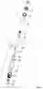
FIG. 1 is an exploded view of an atomizer in accordance with one embodiment of the disclosure;
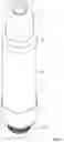
FIG. 2 is a schematic diagram of an atomizer in accordance with one embodiment of the disclosure;
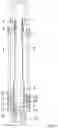
FIG. 3 is a sectional view of an atomizer in accordance with one embodiment of the disclosure;
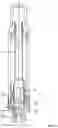
FIG. 4 is a schematic diagram of a cartridge of an atomizer in accordance with one embodiment of the disclosure; and
FIG. 5 shows an airflow direction of an atomizer in accordance with another embodiment of the disclosure.
DETAILED DESCRIPTION
To further illustrate, embodiments detailing an atomizer are described below. It should be noted that the following embodiments are intended to describe and not to limit the disclosure.
As shown in FIGS. 1-5, the disclosure provides an atomizer comprising a mouthpiece 1, a support pad 2, a silicone seal 3, a glass tube 4, a threaded joint 5, a silicone seal ring 6, a cartridge 7, a heating wire 8, a silicone ring 9, a seal ring 10, a decorative ring 11, a silicone gasket 12, a base 13, an insulation ring 14, and an electrode core 15. The cartridge 7 comprises an e-liquid inlet 16, an air inlet 17, and an air outlet 18. The threaded joint 5 comprises a notch and the silicone seal ring 6 is disposed in the notch. One end of the threaded joint 5 is detachably embedded in the top opening of the cartridge 7. The silicone ring 9 is disposed around the lower end of the heating wire 8. The heating wire 8 is disposed in the bottom opening of the cartridge 7. The silicone gasket 12 is disposed in the base 13. The seal ring 10 is disposed around the upper end of the base 13. The electrode core 15 is disposed in the insulation ring 14. The insulation ring 14 is disposed in the cavity of the lower end of the base 13. The decorative ring 11 is disposed around the upper end of the base 13. The lower end of the cartridge 7 is fixed in the base 13. The bottom end of the glass tube 4 abuts against the base 13, and the cartridge 7 is disposed in the glass tube. The mouthpiece 1 is disposed on the support pad 2. The silicone seal 3 is disposed in the lower end of the support pad 2 to seal the top opening of the glass tube 4. The top end of the glass tube 4 abuts against the silicone seal 3 and the threaded joint 5 is in threaded connection to the support pad 2.
When in use, the e-liquid flows to the heating wire 8 via the e-liquid inlet 16 of the cartridge 7. The e-liquid is heated by the heating wire 8 to produce vapor and meanwhile bubbles are produced. The bubbles are discharged from the air outlet 18, thus preventing the bubbles from occupying the cavity of the atomizer so that the e-liquid can flow into the atomizer freely. The base 13 comprises an air hole. The air enters the base 13 via the air hole, and then flows into the cartridge 7 via the air inlet 17 on the lower end of the cartridge 7, to drive the vapor produced by the heating wire 8 to flow from the top opening of the cartridge 7 to the mouthpiece 1 for user's inhaling.
The following advantages are associated with the atomizer of an atomizer of the disclosure:
1. The bubbles are discharged from the air outlet, thus preventing the bubbles from occupying the cavity of the atomizer so that the e-liquid can flow into the atomizer freely.
2. The threaded joint is detachably embedded in the top opening of the cartridge, thus simplifying the assembly of the atomizer.
3. The air inlet and the air outlet are covered by the lower end of the base for separation of e-liquid, thus ensuring the air passage is clear, and the bubbles can be removed through the air outlet.
It will be obvious to those skilled in the art that changes and modifications may be made, and therefore, the aim in the appended claims is to cover all such changes and modifications.
Claims
What is claimed is:1. An atomizer, comprising a glass tube and a cartridge, wherein the cartridge is disposed in the glass tube; the cartridge comprises a side wall comprising an air outlet; and a lower end of the side wall comprises an air inlet.
2. The atomizer of claim 1, further comprising a threaded joint, wherein the threaded joint is detachably embedded in a top opening of the cartridge.
3. The atomizer of claim 1, wherein the side wall of the cartridge further comprises an e-liquid inlet disposed above the air inlet and the air outlet.
4. The atomizer of claim 1, further comprising a heating wire disposed in a lower end of the cartridge.
5. The atomizer of claim 4, further comprising a base; wherein a bottom end of the glass tube abuts against the base; the lower end of the cartridge is fixed in the base; the air inlet and the air outlet are covered by a lower end of the base for separation of e-liquid.
6. The atomizer of claim 5, wherein the base comprises an air hole.
7. The atomizer of claim 6, further comprising a mouthpiece, a support pad, and a silicone seal; wherein the mouthpiece is disposed on the support pad; the silicone seal is disposed on a lower end of the support pad to seal a top opening of the glass tube; a top end of the glass tube abuts against the silicone seal and the threaded joint is in threaded connection to the support pad.
Images & Drawings included:


Sources:
- United States Patent and Trademark Office - verify current appl. status at the USPTO↗
Similar patent applications:
- » 20240068872
ELECTRONIC STATE SPLITTER FOR ATOMS, ATOM INTERFEROMETER ATOMIC TRANSITION FREQUENCY MEASUREMENT DEVICE, ATOMIC OSCILLATOR, OPTICAL LATTICE CLOCK, QUATUM COMPUTER AND METHOD FOR GENERATING SUPERPOSITION OF ELECTRONIC STATES OF ATOMS - » 20250009025
ATOMIZER, ELECTRONIC ATOMIZATION DEVICE, AND ATOMIZATION ASSEMBLY FOR ATOMIZER - » 20240063012
ULTRAVIOLET AND VACUUM ULTRAVIOLET LAMPS DRIVEN BY MOLECULAR-ATOMIC, ATOMIC-ATOMIC, OR ATOMIC-MOLECULAR EXCITATION TRANSFER - » 20240349798
HEATING ATOMIZATION ASSEMBLY, HEATING ATOMIZATION DEVICE, AND ELECTRONIC ATOMIZER COMPRISING HEATING ATOMIZATION DEVICE - » 20240365867
HEATING ATOMIZATION CORE, HEATING ATOMIZATION MECHANISM, HEATING ATOMIZER, AND ELECTRONIC ATOMIZATION DEVICE - » 20250027770
QUANTUM COLLIMATION METHOD FOR ATOMIC BEAM, QUANTUM COLLIMATOR FOR ATOMIC BEAM, ATOMIC INTERFEROMETER, AND ATOMIC GYROSCOPE - » 20060065755
Atomization method, atomizer based on atomization method, and atomization liquid composition - » 20210389114
Method of collimating atomic beam, apparatus for collimating atomic beam, atomic interferometer, and atomic gyroscope - » 20160072439
Atomic cell, atomic cell manufacturing method, quantum interference device, atomic oscillator, electronic device, and moving object - » 20150244382
Atomic cell, manufacturing method for atomic cell, quantum interference device, atomic oscillator, electronic apparatus, and moving object
Recent applications in this class:
- » 20250169535 2025-05-29
AEROSOL DELIVERY DEVICE WITH VISIBLE INDICATOR - » 20250169534 2025-05-29
CARTRIDGE FOR USE WITH APPRATUS FOR HEATING SMOKABLE MATERIAL - » 20250160409 2025-05-22
ATOMIZER AND ELECTRONIC ATOMIZATION APPARATUS - » 20250160408 2025-05-22
APPARATUS FOR HEATING AREOSOL GENERATING MATERIAL - » 20250160407 2025-05-22
AEROSOL DELIVERY DEVICE WITH DOWNSTREAM FLAVOR CARTRIDGE - » 20250160406 2025-05-22
ELECTRONIC CIGARETTE AND NOZZLE ASSEMBLY - » 20250160405 2025-05-22
CONNECTORS FOR FORMING ELECTRICAL AND MECHANICAL CONNECTIONS BETWEEN INTERCHANGEABLE UNITS IN AN AEROSOL DELIVERY SYSTEM - » 20250160404 2025-05-22
ATOMIZERING DEVICE - » 20250151789 2025-05-15
Vaporizer Cartridge With Snap Spring - » 20250143371 2025-05-08
ATOMIZER AND ELECTRONIC ATOMIZATION DEVICE