Ohmni-switch
US20220181098A1
2022-06-09
16/949,173
2020-12-07
✅ Patent granted
US 12,033,826 B2
2024-07-09
-
-
Mark S Rushing
2042-01-19
Abstract:
The Ohmni-Switch is a system that enables a person to use an existing wall switch/receptacle circuit to control outlets that are not wired in that existing wall switch/receptacle circuit. The transmitter and receiver circuits will be housed in a sealed plastic case. All external surfaces of the devices will not have any contact with the house 120 VAC mains.
Assignee:
- Phu D Ngo 1 🇺🇸 Glassboro, NJ, United States
Applicant:
Interested in similar patents?
Get notified when new applications in this technology area are published.
Classification:
H01H9/168 » CPC main
Details of switching devices, not covered by groups - ; Indicators for switching condition, e.g. "on" or "off" making use of an electromagnetic wave communication
H01H9/0271 » CPC further
Details of switching devices, not covered by groups - ; Bases, casings, or covers structurally combining a switch and an electronic component
H01H9/02 IPC
Details of switching devices, not covered by groups - Bases, casings, or covers
H05B47/19 » CPC further
Circuit arrangements for operating light sources in general, i.e. where the type of light source is not relevant; Controlling the light source by remote control via wireless transmission
G08B21/00 IPC
Alarms responsive to a single specified undesired or abnormal condition and not otherwise provided for
H01H2300/032 » CPC further
Orthogonal indexing scheme relating to electric switches, relays, selectors or emergency protective devices covered by; Application domotique, e.g. for house automation, bus connected switches, sensors, loads or intelligent wiring using RFID technology in switching devices
H01H9/16 IPC
Details of switching devices, not covered by groups - Indicators for switching condition, e.g. "on" or "off"
Description
OVERVIEW
The Ohmni-Switch is a system that enables a person to use an existing wall switch/receptacle circuit to control outlets that are not wired in that existing wall switch/receptacle circuit.
The transmitter and receiver circuits will be housed in a sealed plastic case. All external surfaces of the devices will not have any contact with the house 120 VAC mains.
SPECIFICATIONS
Transmitter is equipped with the following components:
- 1. Nema 5-15 Type B plug
- a. This will be used to plug into the standard NEMA 5-15 wall outlet supplying our power supply with 120 VAC.
-
2. 120 VAC to 3.3 VDC, 600 mA power supply
- a. Used to supply 3.3 VDC to our microcontroller, RF module and relay.
- 3. Microcontroller (MSP430)
- a. Programmed send information to the RF modules.
- b. Outputs control the relay.
- 4. Low Power Wireless RF Transmitter Module (NRF24L01)
- a. 2.4 GHz with 125 Channels
- b. Used to facilitate wireless communication between itself and other RF modules in this case the receiver module.
Receiver is equipped with the following components:
- 5. Nema 5-15 Type B plug
- a. This will be used to plug into the standard NEMA 5-15 wall outlet supplying our power supply with 120 VAC.
- 6. 120 VAC to 3.3 VDC, 600 mA power supply
- a. Used to supply 3.3 VDC to our microcontroller, RF module and relay.
- 7. Microcontroller (MSP430)
- a. Programmed receive information from the RF modules.
- b. Outputs control the relay.
- 8. Low Power Wireless RF Transmitter Module (NRF24L01)
- a. 2.4 GHz with 125 Channels
- b. Used to facilitate wireless communication between itself and other RF modules in this case the transmitter.
- 9. General Purpose Relay
- a. 3.3V coil operation
- b. Rated to switch 20 Amps at 120 VAC
- c. Used to switch the load (light, TV, other appliances)
- d. Receives a command from the microcontroller to open or close which will turn the appliance on or off.
- 10. Nema 5-15 Type B receptacle
- a. Used to accept standard 120 VAC, 15 Amp plugs
SUMMARY OF THE INVENTION
The Ohmni-Switch is a system that enables a person to use an existing wall switch/receptacle circuit to control outlets that are not wired in that existing wall switch/receptacle circuit.
Required System Components:
- Ohmni-Switch Transmitter
- Ohmni-Switch Receiver
- Existing wired wall switch and its receptacle
- Receptacle(s) not wired to switch
DESCRIPTION OF THE DRAWINGS
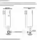
FIG. 1 shows an existing wall with the ohmni switch plugged into the electrical outlet and an ohmni receiver in another electrical outlet.
FIG. 2 shows turning the light ON at a switch where the ohmni switch is plugged into.
FIG. 3 shows turning the light OFF at a switch where the ohmni switch is plugged into.
BEST MODE OF THE INVENTION
FIG. 1 shows the system incorporates the muscle memory of a person flipping an existing wall switch (8) at the existing wall circuit (5) to control the receptacles (3) not wired to the wall switch's circuit (6). The Ohmni-Switch transmitter (2) is designed to plug into a wall receptacle (1) that is control by an existing wall switch (8). When the Ohmni-Switch transmitter (2) is energized by the receptacle (1) via the existing wall switch (8), the Ohmni-Switch transmitter (2) will power up and send an RF command signal to the Ohmni-Switch receiver (4).
FIG. 2 shows the Ohmni-Switch receiver (4) uses the command to energize its receptacle (3), whereby giving energy to the light (7) in the wall switch's circuit (6). The ohmni switch transmitter (2) is to be placed at where any switches (8) are located as the master control. As to the ohmni switch receiver (4), this can be placed at any location in the house, office, or electrical access that is desired to control a light bulb, fan, or electrical devices. The ohmni switch transmitter (2) and the ohmni switch receiver (4) is to minimize or prevent rewiring to the existing home or office.
FIG. 3 shows when the light switch (8) is turned off causing the Ohmni Switch transmitter to de-energized and shutting off electricity to the light bulb (7). Furthermore, the ohmni switch receiver (4) can have multiple controlled receptacles (3) for multiple devices that needs access to power.
Ohmni-Switch Transmitter (2): The transmitter is designed to plug into receptacles and uses a rectifier to power its onboard circuitry. The user can select from multiple RF channels that communicate with Ohmni-Switch receivers on the desired channel.
Ohmi-Switch Receiver (4): The receiver is designed to plug into receptacles and uses a rectifier to power its onboard circuitry. The user can select from multiple RF channels that will pair the receiver up with the desired Ohmni-Switch transmitter.
Ohmni Switch Transmitter (2) is equipped with the following components:
- 1. Nema 5-15 Type B plug
- a. This will be used to plug into the standard NEMA 5-15 wall outlet supplying our power supply with 120 VAC.
- 2. 120 VAC to 3.3 VDC, 600 mA power supply
- a. Used to supply 3.3 VDC to our microcontroller, RF module and relay.
- 3. Microcontroller (MSP430)
- a. Programmed send information to the RF modules.
- b. Outputs control the relay.
- 4. Low Power Wireless RF Transmitter Module (NRF24L01)
- a. 2.4 GHz with 125 Channels
- b. Used to facilitate wireless communication between itself and other RF modules in this case the receiver module.
Ohmni Switch Receiver (4) is equipped with the following components:
- 5. Nema 5-15 Type B plug
- a. This will be used to plug into the standard NEMA 5-15 wall outlet supplying our power supply with 120 VAC.
- 6. 120 VAC to 3.3 VDC, 600 mA power supply
- a. Used to supply 3.3 VDC to our microcontroller, RF module and relay.
- 7. Microcontroller (MSP430)
- a. Programmed receive information from the RF modules.
- b. Outputs control the relay.
- 8. Low Power Wireless RF Transmitter Module (NRF24L01)
- a. 2.4 GHz with 125 Channels
- b. Used to facilitate wireless communication between itself and other RF modules in this case the transmitter.
- 9. General Purpose Relay
- a. 3.3V coil operation
- b. Rated to switch 20 Amps at 120 VAC
- c. Used to switch the load (light, TV, other appliances)
- d. Receives a command from the microcontroller to open or close which will turn the appliance on or off.
- 10. Nema 5-15 Type B receptacle a. Used to accept standard 120 VAC, 15 Amp plugs.
Design Definition:
The Ohmni-Switch is a system that enables a person to use an existing wall switch/receptacle circuit to control outlets that are not wired in that existing wall switch/receptacle circuit.
Required System Components:
- Ohmni-Switch Transmitter
- Ohmni-Switch Receiver
- Existing wired wall switch and its receptacle
- Receptacle(s) not wired to switch
Design Functionality:
The system incorporates the muscle memory of a person flipping an existing wall switch to control the receptacles not wired to the wall switch's circuit. The Ohmni-Switch transmitter is designed to plug into a wall receptacle that is control by an existing switch. When the Ohmni-Switch transmitter's receptacle is energized via the wall switch; the Ohmni-Switch transmitter will power up and send an RF command signal to the Ohmni-Switch receiver. The Ohmni-Switch receiver uses the command to energize its receptacle. When the Ohmni-Switch transmitter's receptacle is de-energized via the wall switch the Ohmni-Switch transmitter will power down and the Ohmni-Switch receiver will de-energize its receptacle.
Ohmni-Switch Transmitter:
The transmitter is designed to plug into receptacles and uses a rectifier to power its onboard circuitry. The user can select from multiple RF channels that communicate with Ohmni-Switch receivers on the desired channel.
Claims
1. A system for allowing to use an existing wall switch and receptacle for powering an electrical device comprising:
An Ohmni switch transmitter having 2.4 Ghz with 125 channels;
An existing electrical receptacle to accept the Ohmni switch transmitter, wherein the existing electrical receptacle has a switch electrically connected thereto;
An Ohmni switch receiver having a microcontroller and a low power wireless RF transmitter module; wherein the ohmni switch receiver configured to be plugged into any electrical except for the existing electrical receptacle;
Images & Drawings included:


Sources:
- United States Patent and Trademark Office - verify current appl. status at the USPTO↗
Recent applications in this class:
- » 20250014842 2025-01-09
SWITCHING DEVICE - » 20210327658 2021-10-21
Electrical power transmission device - » 20200118772 2020-04-16
Control circuits for self-powered switches and related methods of operation - » 20170018377 2017-01-19
Switch apparatus having wireless function - » 20130106199 2013-05-02
MASTER SLAVE RADIO CONTROL SYSTEM - » 20120199454 2012-08-09
Wireless switching device - » 20100314226 2010-12-16
Dual load control device - » 20070171056 2007-07-26
Position switch for non-contacting state identification - » 20060219665 2006-10-05
Control arrangement for switchgear - » 20060213755 2006-09-28
Radio frequency wireless steering wheel