Encased exhaust
US20220396366A1
2022-12-15
17/345,089
2021-06-11
✅ Patent granted
US 11,613,374 B2
2023-03-28
-
-
Michael C Zarroli
2041-06-11
Abstract:
The encased exhaust is a traditional aftermarket expansion chamber muffler system for a two stroke engine encompassing a duct fan/propeller. The propeller is mounted directly to the engine's driveshaft, eliminating reduction gears and belts allowing for more airflow and less weight. This eliminates the muffler and replaces the cage on a paramotor, allowing for more airflow through the funneled air duct. The configuration of these two functions exists but not in this sequence, that is what makes this product unique.
Inventors:
- Stephen Detar 1 🇺🇸 Boston, MA, United States
- Stephen David Detar 1 🇺🇸 Boston, MA, United States
Applicant:
Interested in similar patents?
Get notified when new applications in this technology area are published.
Classification:
F01N13/1833 » CPC further
Exhaust or silencing apparatus characterised by constructional features ; Exhaust or silencing apparatus, or parts thereof, having pertinent characteristics not provided for in, or of interest apart from, groups - , ,; Construction facilitating manufacture, assembly, or disassembly specially adapted for small internal combustion engines, e.g. used in model applications
B64C39/024 » CPC further
Aircraft not otherwise provided for characterised by special use of the remote controlled vehicle type, i.e. RPV
F01N1/12 » CPC further
Silencing apparatus characterised by method of silencing by reducing exhaust energy by throttling or whirling using spirally or helically shaped channels
F02K7/08 » CPC further
Plants in which the working fluid is used in a jet only, i.e. the plants not having a turbine or other engine driving a compressor or a ducted fan; Control thereof the jet being continuous
B64C39/02 IPC
Aircraft not otherwise provided for characterised by special use
F01N13/18 IPC
Exhaust or silencing apparatus characterised by constructional features ; Exhaust or silencing apparatus, or parts thereof, having pertinent characteristics not provided for in, or of interest apart from, groups - , , Construction facilitating manufacture, assembly, or disassembly
B64D33/04 » CPC main
Arrangements in aircraft of power plant parts or auxiliaries not otherwise provided for of exhaust outlets or jet pipes
Description
CROSS-REFERENCE TO RELATED APPLICATIONS
Not-Applicable
STATEMENT REGARDING FEDERALLY SPONSORED RESEARCH OR DEVELOPMENT
Not-Applicable
REFERENCE TO SEQUENCE LISTING, A TABLE, OR A COMPUTER PROGRAM LISTEN COMPACT DISC APPENDIX
Not-Applicable
BACKGROUND OF INVENTION
My father was a professor who had a hobby of building model airplanes, hand-carved gas propeller engines. I was always curious about flight as I watched flocks of birds and airplanes flying overhead. I wanted to fly. I grew up using two-stroke engines on motorcycles, mopeds, snowmobiles, etc. October of the year 2000, I had a dream one night and this idea came to me. I should design an exhaust system for a two-stroke engine that contains a ducted fan with a liner inside or the cylinder. It would funnel the exhaust into the ducting, eliminating the muffler from the system.
This would allow for more airflow from the fan which moves through the duct. I knew this would solve the problem of the traditional exhaust system which contains an exhaust muffler, blocking the airflow. I was able to develop the exhaust system by eliminating the exhaust muffler. I now have a prototype of a product that works with several markets available.
BRIEF SUMMARY OF THE INVENTION
This invention is an expansion chamber exhaust system that encompasses a duct. The duct consists of an inner and outer sleeve, creating an exhaust chamber. The expansion chamber goes around the ducting and bolts to the engine and fan (fan and engine not included in invention). The inner sleeve is an airflow duct. The exhaust chamber is between the inner and outer sleeves. There is an inlet and an outlet to the expansion chamber on the inner wall of the ducting, creating an exhaust for the engine.
BRIEF DESCRIPTION OF THE SEVERAL VIEWS OF THE DRAWING
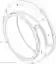
FIG. I depicts the 3D front view of the Encased Exhaust
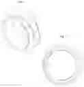
FIG. II shows the inlet section of the Encased Exhaust with two holes, one for the header and one for the outlet (exhaust inlet and exhaust outlet)
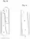
FIG. III depicts the right side view of the Encased Exhaust
FIG. IV shows the left side view of the Encased Exhaust
DETAILED DESCRIPTION OF THE INVENTION
The expansion chamber stages consist of separate pieces of sheet metal formed in an arc shaped bend. These sheet metal sections are welded together at the inlet and outlet sides of the cylinder's ducting, and at the end and beginning of each stage. The inner liner/sleeve/ducting cylinder is welded to the outer sleeve/shell, creating a chamber. They all funnell air flow. The entire cylinder is the bottom of the expansion chamber stages. The width of the sheet metal changes according to the different number of the expansion chamber stages. The propeller is mounted directly to the engine's driveshaft, eliminating reduction gears and belts allowing for more airflow and less weight. The propeller's diameter determines the stages' combined radius. The engine's header connects to the divergent cone.
Reference Characters:
1: Header/Inlet
2: Divergent Cone Stage Diffuser (expands)
3: Divergent Cone Stage Diffuser (expands)
4: Divergent Cone Stage Diffuser (expands)
5: Belly
6: Belly
7: Convergent Cone (contracts)
8: Convergent Cone (contracts)
9: Stinger/Outlet
Claims
1. The encased exhaust is an exhaust propulsion system which replaces the traditional exhaust system
2. It eliminates the muffler and replaces the propeller cage on a paramotor, allowing for more airflow through the funneled air duct
3. The encased exhaust can be used in RC planes and drones
Images & Drawings included:
Sources:
- United States Patent and Trademark Office - verify current appl. status at the USPTO↗
Similar patent applications:
- » 20130202887
Method for encasing a body of an exhaust gas system - » 20160053662
Method for encasing a body of an exhaust gas system
Recent applications in this class:
- » 20250276801 2025-09-04
FLUIDIC PROPULSIVE SYSTEM AND THRUST AND LIFT GENERATOR FOR AERIAL VEHICLES - » 20250083829 2025-03-13
EXHAUST NOZZLE ASSEMBLY FOR AIRCRAFT PROPULSION SYSTEM - » 20250083828 2025-03-13
EXHAUST NOZZLE ASSEMBLY FOR AIRCRAFT PROPULSION SYSTEM - » 20240327016 2024-10-03
AIRCRAFT - » 20240262525 2024-08-08
Exhaust mounting mechanism - » 20240246689 2024-07-25
FLUIDIC PROPULSIVE SYSTEM - » 20240228053 2024-07-11
Fluidic propulsive system and thrust and lift generator for aerial vehicles - » 20240190576 2024-06-13
AIRCRAFT PROVIDED WITH AN ENGINE AND AN EXHAUST DUCT AROUND AN EXHAUST NOZZLE OF THE ENGINE - » 20240182179 2024-06-06
EJECTOR AND AIRFOIL CONFIGURATIONS - » 20240182178 2024-06-06
AIRCRAFT ENGINE WITH EXHAUST HAVING REMOVABLE DEFLECTOR