ELECTRIC CUTTING MACHINE
US20230033763A1
2023-02-02
17/789,731
2020-10-30
✅ Patent granted
US 12,485,580 B2
2025-12-02
WO; PCT/ES2020/070669; 20201030
WO; WO2022/090588; 20220505
Monica S Carter | Kent N Shum
Hodgson Russ LLP
2041-10-21
Abstract:
Disclosed is an electric cutting machine comprising: a base (1); a longitudinally movable table (2); a cutting head (3) provided with a cutting disc (32) and an electric drive motor (33); two rolling assemblies (4) with wheels (41) and rolling bearings (43) mounted by means of independent axles (42, 44) on a vertical partition (52) of parallel longitudinal profiles (5) mounted on the base (1); a pair of longitudinal guides (6) attached to the movable table (2) and which comprise a longitudinal support track (63) for supporting on the wheels (41) of the corresponding rolling assembly (4), and a horizontal wing (65) located under the rolling bearings (43) of the corresponding rolling assembly (4); and interchangeable longitudinal guides (6a) longer than the longitudinal guides (6), for adapting the cutting capacity.
Assignee:
- GERMANS BOADA, S.A. 12 🇪🇸 Rubi, Spain
Applicant:
Interested in similar patents?
Get notified when new applications in this technology area are published.
Classification:
B28D1/047 » CPC main
Working stone or stone-like materials, e.g. brick, concrete or glass , not provided for elsewhere; Machines, devices, tools therefor by sawing with circular or cylindrical saw-blades or saw-discs with the work mounted on a carriage
B23D47/025 » CPC further
Sawing machines or sawing devices working with circular saw blades, characterised only by constructional features of particular parts of frames; of guiding arrangements for work-table or saw-carrier of tables
B28D1/04 IPC
Working stone or stone-like materials, e.g. brick, concrete or glass , not provided for elsewhere; Machines, devices, tools therefor by sawing with circular or cylindrical saw-blades or saw-discs
B23D47/02 IPC
Sawing machines or sawing devices working with circular saw blades, characterised only by constructional features of particular parts of frames; of guiding arrangements for work-table or saw-carrier
F16C29/04 » CPC further
Bearings for parts moving only linearly Ball or roller bearings
B23D1/006 » CPC further
Planing or slotting machines cutting by relative movement of the tool and workpiece in a horizontal straight line only for planing elongated workpieces Rails
B23D1/02 » CPC further
Planing or slotting machines cutting by relative movement of the tool and workpiece in a horizontal straight line only by movement of the work-support
B23D1/04 » CPC further
Planing or slotting machines cutting by relative movement of the tool and workpiece in a horizontal straight line only by movement of the work-support with the tool supported only on one side of the bed
F16C2322/34 » CPC further
Apparatus used in shaping articles Sawing machines
B23D1/00 IPC
Planing or slotting machines cutting by relative movement of the tool and workpiece in a horizontal straight line only
B23D1/00 IPC
Planing; Slotting
Description
CROSS-REFERENCE TO RELATED APPLICATION
This application is a U.S. national stage entry of International Application No. PCT/ES2020/070669, filed Oct. 30, 2020, the entire disclosure of which is incorporated herein by reference.
FIELD
The present invention relates to an electric cutting machine of the type of those used in the construction industry for cutting various pieces, such as: tiles, floor tiles, ceramic plates or other similar pieces.
BACKGROUND
Electric cutting machines used for cutting tiles and similar construction pieces are well known today on the market, said machines having a base on which the following are mounted: a movable table provided with an upper surface for supporting the piece to be cut, and an adjustable cutting head provided with a cutting disc driven by an electric motor.
Those cutting machines that most resemble the cutting machine object of the present invention have a cutting head fixed to the base by means of a fixed arm, such that said head is located above the movable table.
Said cutting head is also known to be rotatable with respect to an axis parallel to the movement direction of the table, so as to be located perpendicular to same and to make a vertical cut along the piece, or with different inclinations so as to make a bevelled cut, for example at 45 or 60 degrees, along the piece. Said cutting head also rotates with respect to an axis perpendicular to the movement direction of the table in order to change the cutting depth.
In cutting machines of this type, the head does not move in the cutting direction, as it is the table that is in charge of moving the piece to be cut with respect to the base and the cutting head.
For the longitudinal movement of the table, these cutting machines comprise parallel guides fixed to the base of the machine and rolling means fixed to the table and moving along the guides of the base, allowing the longitudinal movement of the table under the cutting head.
With the mentioned arrangement, i.e., with the guides fixed to the base and the rolling means fixed to the table, cutting machines with different embodiments are known.
Document U.S. Pat. No. 7,455,003 discloses an electric saw comprising: substantially parallel first and second rail assemblies arranged on the base; a first rolling assembly mounted on an axle coupled to the table and having a roller and a first bearing and a second bearing assembly having a second bearing coupled to the table; and wherein the roller rolls over a first surface of the first rail assembly for the table to slide along the first rail assembly, whereas the first bearing is supported against a second surface of the first rail assembly and prevents the table from being lifted off the base. This document contemplates the guiding and movement means of the table allowing said table to be cantilevered with respect to the end of the base in order to increase its movement range.
Document US2009/0277315A1 discloses a tile saw that includes a base with two parallel guides and a table with pairs of wheels vertically spaced apart and located, respectively, above and below the corresponding guide, allowing the longitudinal movement of the table along the guides of the base.
Other documents, i.e., U.S. Pat. Nos. 5,676,124 and 6,000,387A, likewise describe guiding means fixed to the base of the electric saw and rolling means fixed to the movable table.
These background documents present a series of drawbacks, among which the difficulty in adapting the cutting machine to different cutting capabilities and the risk of misalignment of the rollers due to impacts during transport of the machine with the table being removed, can be mentioned.
SUMMARY
The electric cutting machine of the invention comprises: a base on which there are mounted a movable table provided with an upper surface for supporting the piece to be cut, and an adjustable cutting head provided with a cutting disc driven by an electric motor; it presents technical features which allow the aforementioned drawbacks to be resolved.
According to the invention, the cutting machine comprises two rolling assemblies mounted on the base of the cutting machine by means of parallel longitudinal profiles comprising a lower surface fixed to said base and a vertical partition facing the upper area; comprising each rolling assembly: wheels and rolling bearings arranged on opposite sides of the vertical partition of the corresponding vertical profile, spaced apart along said longitudinal profile and mounted by means of independent axles on said vertical partition.
Said cutting machine comprises a pair of longitudinal guides fixed in the lower portion to the movable table, and comprising an upper surface which is prolonged towards the lower area in a first arm and in a second arm ending respectively in a longitudinal support track on the wheels of the corresponding rolling assembly of the base, and in a horizontal wing facing the first arm and located under the rolling bearings of the corresponding rolling assembly.
The mounting of the rolling assemblies on the base and the mounting of the longitudinal guides on the movable table provide a series of advantages, in terms of both the manufacture and the use, namely:
-
- Given that the wheels and the rolling bearings are on the base, and not on the table, guides as long as desired can be mounted on the movable tables to obtain a higher cutting capacity without adding rolling elements (wheels or rolling bearings) and without modifying the base of the cutting machine.
- It facilitates the installation of the table in the saw insofar as it is more quickly aligned and advances more quickly.
- It is easier to align the saw, and such alignment is maintained for more time.
- The machine can be packaged without the table, and the rolling assemblies, which are mounted on the base, maintain their factory alignment when the client assembles the machine and mounts the movable table on the rolling assemblies.
- When the table is removed for cleaning, the rolling assemblies remain mounted on the base and aligned, eliminating the risks of impact and misalignment to which they are exposed when mounted on the table.
According to the invention, the machine comprises removable means for fixing the longitudinal guides to the movable table and at least two interchangeable pairs of longitudinal guides of a different length.
Advantageously, at least one of the interchangeable pairs of longitudinal guides has a longer length than the movable table, which allows the movement range of the table in the longitudinal direction, and accordingly the cutting capacity, to be increased without needing to change the movable table or increase the number of rolling assemblies existing on the base, which would entail greater alignment difficulty.
This feature allows the same cutting machine to have a significantly different cutting capacity, maintaining most of the pieces. This also allows the sale of table assemblies and accessories for updating the client's cutting machine. This provides greater flexibility for generating cutting machines with different features and accessories such that they can be personalised.
BRIEF DESCRIPTION OF THE DRAWINGS
As a complement to the description provided herein, and for the purpose of helping to make the features of the invention more readily understandable, the present specification is accompanied by a set of drawings which, by way of illustration and not limitation, represent the following:
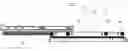
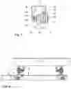
FIG. 1 shows a schematic plan view of an exemplary embodiment of the cutting machine according to the invention.
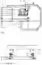
FIG. 2 shows a profile view of the base of the cutting machine with the rolling assemblies and of the movable table, which bears the longitudinal guides, removed and moved vertically with respect to the base.
FIG. 3 shows a profile view of a longitudinal guide of the movable table mounted on one of the rolling assemblies.
FIG. 4 shows a profile view of the movable table of the cutting machine mounted by means of the corresponding longitudinal guides on the rolling assemblies of the base of the cutting machine.
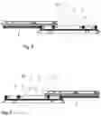
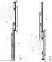
FIGS. 5 and 6 show respective elevation views of the movable table mounted in two end positions on the rolling assemblies of the base of the cutting machine.
FIGS. 7 and 8 show respective views similar to FIGS. 5 and 6, respectively, and in which the guides of the movable table have been replaced with other longer guides.
DETAILED DESCRIPTION
The cutting machine depicted in FIG. 1 comprises a base (1) on which is mounted: a movable table (2) in longitudinal direction for the support of the pieces to be cut, and a cutting head (3) fixed to the base (1) by means of an arm (31).
Said cutting head (3) has a cutting disc (32) driven by means of an electric motor (33) and can rotate with respect to a longitudinal axis and with respect to a transverse axis in order to change the lateral inclination of the cutting disc (32) and the cutting depth, respectively.
As shown in FIG. 2, on the base (1) there are mounted longitudinal support profiles (5) for supporting the rolling assemblies (4) suitable for the support and longitudinal movement of longitudinal guides (6) fixed to the lower surface of the movable table (2).
As observed in FIG. 3, the longitudinal profiles (5) in charge of supporting the rolling assemblies (4) comprise a lower surface (51) intended for being fixed to the base (1) of the cutting machine, as shown in FIG. 2, and a vertical partition (52) facing the upper area.
The rolling assemblies (4) comprise wheels (41) arranged on the outer side of the corresponding longitudinal profile (5), and rolling bearings (43) arranged on the inner side of the longitudinal profile (5).
The wheels (41) and the rolling bearings (43) are spaced apart along said longitudinal profile (5) and mounted by means of independent axles (42, 44) on said vertical partition (52).
FIG. 3 also depicts the corresponding longitudinal guide 6 comprising an upper surface (61) intended for being fixed with removable means, in this case screws (not depicted), to the lower surface of the movable table (2).
The upper surface (61) of the longitudinal guides (6) is prolonged towards the lower area in a first arm (62) ending in a longitudinal track (63) and in a second arm (64) ending in the lower portion in a horizontal wing (65) facing the first arm (62).
As shown in FIG. 4, in the mounting position of the movable table (2), the longitudinal track (63) of the longitudinal guides (6) fixed to said movable table is supported on the wheels (41) of the rolling assemblies (4) mounted on the base (1), and the horizontal wing (65) of the longitudinal guides (6) is located under the rolling bearings (43) of said rolling assemblies.
FIGS. 5 and 6 schematically depict the cutting disc (32) to provide a positional reference of the carriage at the two end positions of movement with respect to the base (1). In said figures, the movable table (2) has a pair of longitudinal guides (6) having a length similar to that of said table.
FIGS. 7 and 8 depict the movable table (2) of FIGS. 5 and 6, provided in this case with a pair of guides (6a), longer than the longitudinal guides (6), which allow the movement range of said movable table (2), and accordingly the cutting capacity of the machine, to be increased without modifying the base (1) or the rolling assemblies (4) mounted on said base (1).
Having sufficiently described the nature of the invention, in addition to a preferred exemplary embodiment, it is hereby stated for the relevant purposes that the materials, shape, size and layout of the described elements may be modified, provided that it does not imply altering the essential features of the invention claimed below.
Claims
1. An electric cutting machine, comprising:
a base;
a movable table mounted on the base configured to move in a longitudinal cutting direction and forming a support surface for a tile or piece to be cut;
an adjustable cutting head mounted on the base and comprising a cutting disc located above the movable table and an electric drive motor;
two rolling assemblies mounted on the base of the cutting machine by means of parallel longitudinal profiles comprising a lower surface fixed to said base and a vertical partition facing an upper area; each rolling assembly comprising: wheels and rolling bearings arranged on opposite sides of the vertical partition of a corresponding longitudinal profile, spaced apart along said longitudinal profile and mounted by means of independent axles on said vertical partition; and
a pair of longitudinal guides fixed in a lower portion to the movable table, and comprising an upper surface which is prolonged towards the lower area in a first arm and in a second arm ending respectively in a longitudinal support track for supporting on the wheels of a corresponding rolling assembly and in a horizontal wing facing the first arm and located under the rolling bearings of the corresponding rolling assembly.
2. The machine according to claim 1, further comprising at least two interchangeable pairs of longitudinal guides of a different length and configured to be removably attachable for alternative fixing thereof to the movable table.
3. The machine according to claim 2, wherein at least one of the interchangeable pairs of longitudinal guides has a longer length than the movable table.
Images & Drawings included:
Sources:
- United States Patent and Trademark Office - verify current appl. status at the USPTO↗
Similar patent applications:
- » 20160094115
Linear actuator, electric brush, electric cutting machine and electric air pump - » 20130283622
HAND-HELD ELECTRIC CUTTING MACHINE - » 20180222078
ELECTRIC CUTTING MACHINE WITH DUST CONTROL FUNCTION - » 20220252095
Locking mechanism for folding chassis of electric cutting machines - » 20120305530
Wire-cut electric discharge machine with wire electrode cutting function - » 20080201010
PUNCH MACHINING PROGRAM GENERATING DEVICE, RECORDING MEDIUM STORING A PROGRAM FOR GENERATING A PUNCH MACHINING PROGRAM, AND WIRE-CUT ELECTRIC DISCHARGE MACHINE - » 20050040142
Machining control method for wire-cut electric discharge machine - » 20060219668
Machining fluid level detection device for wire cut electrical discharge machines - » 20050267624
Used wire cutting device for wire cut electric discharge machine - » 20050242065
Wire-cut electric discharge machine
Recent applications in this class:
- » 20240217138 2024-07-04
TILE SAW WITH ADJUSTABLE FENCE AND METHODS - » 20240075653 2024-03-07
TILE SAW - » 20230048821 2023-02-16
MACHINE FOR PRODUCING MARBLE TILES AND RELATED METHOD - » 20220193952 2022-06-23
Worktable assembly for tile cutter - » 20220168924 2022-06-02
TILE SAW - » 20220024072 2022-01-27
ADJUSTMENT DEVICE FOR MACHINES FOR CUTTING FLOOR TILES AND SIMILAR - » 20210387377 2021-12-16
TILE SAW - » 20200180186 2020-06-11
TILE SAW - » 20200180185 2020-06-11
Tile saw with adjustable fence and methods - » 20200094438 2020-03-26
Tile or masonry saw dust collection arrangement
Recent applications for this Assignee:
- » 20240102294 2024-03-28
PROTECTIVE DEVICE FOR CERAMIC PIECES - » 20240058991 2024-02-22
CUTTING DEVICE FOR MANUAL CERAMIC CUTTERS - » 20230243164 2023-08-03
Device for levelling and separating floor tiles - » 20230144749 2023-05-11
Electric saw - » 20220372772 2022-11-24
Floor tile levelling device - » 20220252095 2022-08-11
Locking mechanism for folding chassis of electric cutting machines - » 20220118651 2022-04-21
Manual ceramic cutter with adjustable set-square - » 20220118650 2022-04-21
Manual ceramics cutter with detachable accessories - » 20210252731 2021-08-19
Cooling device for disc cutters - » 20200307666 2020-10-01
Transporter for large-format building boards