SYSTEM AND METHOD FOR CIRCLE AND CURVE DRAWING TEMPLATE
US20230043698A1
2023-02-09
17/882,563
2022-08-06
✅ Patent granted
US 12,391,061 B2
2025-08-19
-
-
Yaritza Guadalupe-McCall
Bold IP, PLLC | Christopher Mayle
2043-11-15
Abstract:
A system and method for a template tool to create large curves for material layout, form-making, and construction or other shapes that cannot be handedly formed or accomplished indoors or outside where lack of space or where obstructions exist whereby the template may be used as a simple drafting tool to ‘sweep’ small curves about the ‘O’ center point, or with 1- or 2-point methods to produce larger vertical and horizontal circular layouts for arches, circles, and anything that requires a circular shape.
Applicant:
Interested in similar patents?
Get notified when new applications in this technology area are published.
Classification:
B43L13/20 » CPC main
Drawing instruments, or writing or drawing appliances or accessories not otherwise provided for Curve rulers or templets
Description
CROSS REFERENCE TO RELATED APPLICATIONS
This application claims priority to U.S. Non Provisional application No. 63/230,730 filed on Aug. 7, 2021.
FIELD OF THE DISCLOSURE
The overall field of this invention relates to a template for drawing curves or circles and more particularly to a template with multiple apertures for forming different sized circles or three dimensional items for layout, forming, and construction.
BACKGROUND
The circle is the strongest 2-dimensional shape; so is the use of semicircular arches in architecture. Semicircles are often also found in the designs of amphitheaters. Large curves for material layout, form-making, and construction cannot be handedly formed or accomplished indoors or outside where lack of space or obstructions exist. Currently existing technology requires a limited extended tape measure or a survey method to provide as consistent angle as shown in FIG. 1 or are very complicated as shown in FIG. 2. Thus exists the need for a curve drawing template to draw large curves without the need for excessive tools.
SUMMARY
The present invention is directed to a curve drawing template to draw large curves without the need for excessive tools. The template can be used as a simple drafting tool to ‘sweep’ small curves about the ‘O’ center point, or with 1- or 2-point methods, anyone can produce larger vertical and horizontal circular layouts for arches, circles, and anything that requires a circular shape. When the physical center of a curve or circle is obstructed or too large to “sweep” an arc of a measured radius, our methods can be used, by an individual, to produce many sized curves, curve segments, curves in tight or interior areas, and full circles without ‘sweeping’ from a physical center.
BRIEF DESCRIPTION OF THE DRAWINGS
Embodiments of the present disclosure are described in detail below with reference to the following drawings. These and other features, aspects, and advantages of the present disclosure will become better understood with regard to the following description, appended claims, and accompanying drawings. The drawings described herein are for illustrative purposes only of selected embodiments and not all possible implementations and are not intended to limit the scope of the present disclosure.
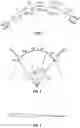
FIG. 1 illustrates a prior art diagram.
FIG. 2 illustrates another prior art diagram.
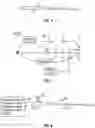
FIG. 3 illustrates a 90 degree right angle triangle to show the offset distance.
FIG. 4 illustrates a near right angle triangle formed using the template tool.
FIG. 5 illustrates methods of drawing a circle.
FIG. 6 illustrates the creation of a curve using the one point method.
FIG. 7 illustrates the method of the creation of a curve using the one point method.
FIG. 8 illustrates the method of the creation of a curve using the one point method.
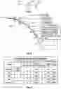
FIG. 9 illustrates a table showing the method of the creation of a curve using the one point method.
FIG. 10 illustrates a curve using the one point method.
FIG. 11 illustrates the creation of a curve using the two point method.
FIG. 12 illustrates the method of the creation of a curve using the two point method.
FIG. 13 illustrates a curve using the two point method.
FIG. 14 illustrates a table showing the method of the creation of a curve using the two point method.
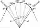
FIG. 15 illustrates a one foot template tool.
FIG. 16 illustrates the curves created with the one foot template tool.
DETAILED DESCRIPTION
In the Summary above and in this Detailed Description, and the claims below, and in the accompanying drawings, reference is made to particular features (including method steps) of the invention. It is to be understood that the disclosure of the invention in this specification includes all possible combinations of such particular features. For example, where a particular feature is disclosed in the context of a particular aspect or embodiment of the invention, or a particular claim, that feature can also be used, to the extent possible, in combination with and/or in the context of other particular aspects and embodiments of the invention, and in the invention generally.
The term “comprises” and grammatical equivalents thereof are used herein to mean that other components, ingredients, and steps, among others, are optionally present. For example, an article “comprising” (or “which comprises”) components A, B, and C can consist of (i.e., contain only) components A, B, and C, or can contain not only components A, B, and C but also contain one or more other components.
Where reference is made herein to a method comprising two or more defined steps, the defined steps can be carried out in any order or simultaneously (except where the context excludes that possibility), and the method can include one or more other steps which are carried out before any of the defined steps, between two of the defined steps, or after all the defined steps (except where the context excludes that possibility).
The term “at least” followed by a number is used herein to denote the start of a range beginning with that number (which may be a range having an upper limit or no upper limit, depending on the variable being defined). For example, “at least 1” means 1 or more than 1. The term “at most” followed by a number is used herein to denote the end of a range ending with that number (which may be a range having 1 or 0 as its lower limit, or a range having no lower limit, depending upon the variable being defined). For example, “at most 4” means 4 or less than 4, and “at most 40%” means 40% or less than 40%. When, in this specification, a range is given as “(a first number) to (a second number)” or “(a first number)−(a second number),” this means a range whose lower limit is the first number and whose upper limit is the second number. For example, 25 to 100 mm means a range whose lower limit is 25 mm and upper limit is 100 mm.
Certain terminology and derivations thereof may be used in the following description for convenience in reference only and will not be limiting. For example, words such as “upward,” “downward,” “left,” and “right” would refer to directions in the drawings to which reference is made unless otherwise stated. Similarly, words such as “inward” and “outward” would refer to directions toward and away from, respectively, the geometric center of a device or area and designated parts thereof. References in the singular tense include the plural, and vice versa, unless otherwise noted.
The present disclosure is generally drawn to a system and method, according to one or more exemplary embodiments, for a tool to create large curves for material layout, form-making, and construction or other shapes that cannot be handedly formed or accomplished indoors or outside where lack of space or obstructions exist.
The principle behind the tool is that any radius, R, represented by a tangent, T1≤0.1R, with an additionally proportionate tangent, T2≤0.2R, and with proportionate offsets, a1≤0.01R & a2≤0.02R, of a circular outline of a curve may be created, which most nearly represents the circular curve of radius R when drawn by a tangent-offset method described in this patent. To create a curve of radius R with this tool, 5 points must be defined; the origin, “O”, the 2 points which represent the distances, along a centerline, of T1≤0.1R and T2≤0.2R from the origin, and 2 projected offsets distances of a1≤0.01R, projected from T1, and a2≤0.02R, projected from T2. Both are distances of T1≤0.1R and T2≤0.2R, respectfully from the origin and proportionately, on the curves formed by the curve projection of T1 and T2. “A” is an offset from a tangent projection of some length ‘T’ from the first point of the curve template ‘O.’ This may be visualized in FIG. 3 that depicts a near 90° triangle with a very narrow point. This is how the methods of tracing with the template work together. These provide for the foundation of the invention. A near right-angle triangle is formed using the template as shown in FIG. 4. When the template holes, “O,” with 2 holes along the center line are selected and marked, tangents 1T and 2T respectfully, and offsets 1a & 2a are also marked, this creates 5 marks in total “O, 1T, 1a, 2T, and 2a”.
An illustration of curve template tool is shown in FIG. 15. Curve template tool has a series of holes used to create circles with a 1-foot radius to 10 foot using a 1-point method and a 2 foot radius to 20 foot radius using a 2 point method as illustrated in FIG. 16. The 1-Point Method is a direct method to find a curve with the least number of marks. The 2-Point Method has a “refined” outcome from the 1-Point Method. The 2-Point Method forms a curve that is “twice” the curve radius produced by the 1-Point Method using the same 5 holes as illustrated in FIG. 5. Example: Using 1a=#2 and 2a=#4@1T=2 and 2T=4, the 2-Point Method produces a 48″ diameter circle and the 1-Point Method produces a 24″ diameter circle.
To begin creating a circle with the 1-Point Method as illustrated in FIG. 6, first 5 points are marked, then the template tool is shifted up, holding the template “O” hole over the “O” mark, the template “1T” hole is aligned over the “1a” mark. “2a-1(8)” is then marked. (8) is an interim hole halfway between (7) & (9). The template is then slid forward where “O” template hole is placed over the “1a-(( ))” mark. The template “1T” hole is then aligned over the “2a-1(8)” mark, and “3a-1(9)” is marked. The realignment of holding “O” at the next “#a-1(9)” is then repeated whereby template hole “1T” is aligned at the next #a-1(9) and the successive #a-1(9) is marked. This method may be continued until the desired circle or length of curve is achieved.
For example, in the creation of a 1-foot radius circle using the 1-point method as illustrated in FIG. 6 using curving template tool of FIG. 15, whereby the Origin, “O” is 1, the set of holes, “a1” (upper) is 2; “T1” (center) is 3, “a1” (lower) is 4; “a2” (upper) is 5, “T2” (center) is 7, and “a2” (lower) is 9. The method begins by marking tangent distances “1T and 2T” and offsets “a1 and a2” from the origin or points 1, 3, 4, 7, and 9. The next step is a key difference. Hold the template “O” over the mark for “O” (1) and “sweep” the template to align ‘1T’ (3) over ‘a1’ (4) mark. Mark “2a-1” (8), as shown in FIG. 7. Secondly, move the template ahead to place the template “O” hole over the “1a” (4) mark. Align the template so that the “1T” (3) hole rests over the interim “2a-1” (8) mark. Mark “3a-1” (next 9), as shown below. Move ahead and realign the template holding “O” (1) at the next “#a-1” (3), aligning template hole “1T” at the next “#a-1” (9) & marking #a-1(9). Continue this method of marking until the desired circle or length of curve is achieved as shown in FIGS. 8, 9, and 10.
To begin creating a circle with the 2-Point Method as illustrated in FIG. 11, first 5 points are marked, then move the template, as shown in FIG. 11, to center the “O” (1) hole over the mark “1a” (4) and align template “1T” (3) hole over the mark “2a” (9). Mark a new “2a-1” (4) & “3a” (9). Then move the template ahead to place the “O” hole over the “2a-1” mark, as shown in FIG. 12, & align the template “1T” hole over “3a” mark. Mark “3a-1,” & “4a”. Repeat the realignment of “O” at “#a-1”, aligning template hole “1T” at the next “(#+1} a”, & marking the next “(#+1)a-1” & “(#+2)a”. Continue this method of marking until the desired circle or length of curve is achieved as shown in FIGS. 13 and 14. Make your curve alignment from the “#a-1” (4) marks; use the “#T” (9) marks for off-set work as shown in FIG. 13.
The embodiments were chosen and described in order to best explain the principles of the invention and the practical application, and to enable others of ordinary skill in the art to understand the invention for various embodiments with various modifications as are suited to the particular use contemplated. The present invention according to one or more embodiments described in the present description may be practiced with modification and alteration within the spirit and scope of the appended claims. Thus, the description is to be regarded as illustrative instead of restrictive of the present invention.
Claims
What is claimed is:1. A method for creating one or more curves or circles using a template, the method comprising:
creating a tangent length from an origin point that is less than or equal to 10% of a desired curve radii;
creating an offset from an end of the tangent length, wherein the offset is less than or equal to 10% of the tangent length; and
creating an additional length that is connected to the origin point and the offset and is equidistant from the origin point as the tangent length.
2. The method of claim 1 further comprising:
creating a second tangent length that is twice the length of the tangent length with an end of the second tangent length twice the distance to the origin point than the tangent length;
marking a first template mark at a first template hole at the origin point;
marking a second template mark at a second template hole at the end of the tangent length; and
marking a third template mark at a third template hole at the end of the second tangent length.
3. The method of claim 2 further comprising:
creating a second offset and a second additional length to form two near right angle triangles;
marking a fourth template mark at a fourth template hole at an upper end of the first offset; and
marking a fifth template mark at a fifth template hole at an upper end of the second offset.
4. The method of claim 3 further comprising:
drawing the curve or the circle using the five template holes by the use of the template to spin about the origin point.
5. The method of claim 3 further comprising:
drawing the curve or the circle using the five template holes by a one point method or a two point method, wherein the two point method forms a curve that is twice the size of a curve produced by the one point method.
6. The method of claim 3 further comprising:
drawing the curve or the circle of the one or more curves or circles using a one point method;
holding the first template mark over the origin point;
sweeping the template to align the second template hole over the fourth template mark; and
marking a sixth template mark at an interim offset.
7. The method of claim 6 further comprising:
moving the template ahead to place the first template hole over the fourth template mark;
align the template such that the second template hole is positioned over the sixth template mark; and
marking a seventh template mark.
8. The method of claim 7 further comprising:
moving the template ahead to place the first template hole over the sixth template mark;
align the template such that the second template hole is positioned over the seventh template mark; and
marking an eight template mark.
9. The method of claim 8 further comprising:
continue aligning and marking until a desired circle or length of curve is achieved.
10. The method of claim 3 further comprising:
Drawing the curve or the circle of the one or more curves or circles using a two point method;
holding the first template mark over the origin point;
sweeping the template to align the second template hole over the fourth template mark; and
marking a sixth template mark at an interim offset.
11. The method of claim 10 further comprising:
moving the template ahead to place the first template hole over the fourth template mark;
align the template such that the second template hole is positioned over the sixth template mark; and
marking a seventh template mark and an eighth template mark.
12. The method of claim 11 further comprising:
moving the template ahead to place the first template hole over the sixth template mark;
align the template such that the second template hole is positioned over the eighth template mark; and
marking a ninth and tenth template mark and an eighth template mark.
13. The method of claim 12 further comprising:
continue aligning and marking until desired circle or length of curve is achieved.
14. A template for creating one or more curves or circles using a template, the template comprising;
a tangent length from an origin point that is less than or equal to 10% of a desired curve radii;
an offset from an end of the tangent length, wherein the offset is less than or equal to 10% of the tangent length; and
an additional length that is connected to the origin point and the offset and is equidistant from the origin point as the tangent length.
15. The template of claim 14 further comprising:
a second tangent length that is twice the length of the tangent length with an end of the second tangent length twice the distance to the origin point than the tangent length;
16. The template of claim 15 further comprising:
a second offset and a second additional length to form two near right angle triangles.
17. The template of claim 16, wherein the curve or the circle of the one or more curves or circles is constructable using five template holes by the use of the template to spin about the origin point.
18. The template of claim 16, wherein the curve or the circle of the one or more curves or circles is constructable using five template holes by a one point method or a two point method, wherein the two point method forms a curve that is twice the size of a curve produced by the one point method.
19. A template for creating one or more curves or circles, the template comprising a plurality of holes, wherein the template is configured to construct the one or more curves or circles to have a radius of one foot to a radius of twenty feet.
20. The template of claim 19, wherein the template has forty five template holes in twelve arching formations facing an origin point template hole.
Images & Drawings included:


Sources:
- United States Patent and Trademark Office - verify current appl. status at the USPTO↗
Recent applications in this class:
- » 20200062024 2020-02-27
Old work box device - » 20160214425 2016-07-28
Writing Template - » 20140047725 2014-02-20
Pipe fitting layout system - » 20100229773 2010-09-16
Method and Template for Creating Hexagon Patterns in Quilting - » 20060225291 2006-10-12
Pipe cutting template - » 20050252019 2005-11-17
Quilting template - » 15880430 2020-07-28
Stair layout template and method for using the template