OPTIMAL SCHEDULING METHOD FOR PEAK REGULATION OF CASCADE HYDRO-PHOTOVOLTAIC COMPLEMENTARY POWER GENERATION SYSTEM
US20230367280A1
2023-11-16
18/331,949
2023-06-09
Abstract:
Disclosed is an optimal scheduling method for peak regulation of a cascade hydro-photovoltaic complementary power generation system. The method includes: establishing an objective function of optimal scheduling for peak regulation of the cascade hydro-photovoltaic complementary power generation system; establishing a photovoltaic power station output constraint condition considering uncertainty; optimizing a mixed integer linear model by performing linear processing on the constraint condition; and obtaining a scheduling solution by solving the mixed integer linear model. According to the present disclosure, a unit commitment of a hydro-power station and an operational solution of a reservoir are considered, so that photovoltaic output can be consumed by fully using a characteristic that the hydro-power unit is easy to regulate, and a demand for peak regulation of a power grid can be satisfied.
Inventors:
- Wei JIANG 7 🇨🇳 Kunming, China
- Jian Zhou 2 🇨🇳 Kunming, China
- Yang Li 1 🇨🇳 Kunming, China
- Dacheng Li 2 🇨🇳 Kunming, China
- Feng Wu 2 🇨🇳 Kunming, China
- Huawei Xiang 2 🇨🇳 Kunming, China
- Yun Tian 2 🇨🇳 Kunming, China
- Yifan Bao 1 🇨🇳 Kunming, China
- Di Wu 2 🇨🇳 Kunming, China
- Xu Li 2 🇨🇳 Kunming, China
- Linjun Shi 1 🇨🇳 Kunming, China
- Wenbo Huang 2 🇨🇳 Kunming, China
- Xinglin Duan 1 🇨🇳 Kunmingn, China
- Keman Lin 1 🇨🇳 Kunming, China
- Yanqing Zhang 2 🇨🇳 Kunming, China
Interested in similar patents?
Get notified when new applications in this technology area are published.
Classification:
G05B2219/2639 » CPC further
Program-control systems; Pc systems; Pc applications Energy management, use maximum of cheap power, keep peak load low
G05B19/042 » CPC main
Programme-control systems electric; Programme control other than numerical control, i.e. in sequence controllers or logic controllers using digital processors
Description
TECHNICAL FIELD
The present disclosure relates to the technical field of optimal scheduling for a multi-energy complementary power generation system, in particular to an optimal scheduling method for peak regulation of a cascade hydro-photovoltaic complementary power generation system.
BACKGROUND TECHNOLOGY
As renewable clean energy power generation technologies develop by leaps and bounds, installed capacities of photovoltaic power stations increase substantially in recent ten years. As photovoltaic power generation is characterized by strong randomness, intermittency and volatility, it is difficult to match photovoltaic outputs with load demands in a power system. In order to satisfy peak regulation demand of the power system, flexible power supplies need to be introduced to cooperate with the photovoltaic power generation. In addition, hydro-power generating units feature a quick start-stop, a large regulation range, fast regulation, etc., providing sufficient peak regulation capacities for the power system. Therefore, cascade hydro-photovoltaic complementary power generation can make full use of the regulation performance of cascade hydro-power station groups, realizing efficient utilization of renewable energy and safe and stable operation of a grid.
Currently, scholars at home and abroad have performed studies on optimal scheduling of a grid-connected photovoltaic power generation system. Most of them only consider a hydro-power station as a whole, without involving a unit commitment in a cascade hydro-power station. Moreover, synergistic peak regulation of cascade hydro-power units and photovoltaic power stations has not yet been studied deeply.
SUMMARY OF THE DISCLOSURE
An objective of the present disclosure is to provide an optimal scheduling method for peak regulation of a cascade hydro-photovoltaic complementary power generation system, and to provide a unit commitment power generation solution, satisfying a peak regulation demand of the power grid, for the cascade hydro-photovoltaic complementary power generation system.
In order to realize the above objective, the technical solutions employed in the present disclosure are as follows:
The present disclosure provides an optimal scheduling method for peak regulation of a cascade hydro-photovoltaic complementary power generation system, including:
-
- establishing an objective function of optimal scheduling for peak regulation of the cascade hydro-photovoltaic complementary power generation system; and
- establishing a cascade hydro-power constraint condition considering a unit commitment and a photovoltaic power station output constraint condition considering uncertainty;
- performing linear processing on the constraint condition, and establishing a mixed integer linear model of optimal scheduling for peak regulation of the cascade hydro-photovoltaic complementary power generation system on the basis of the objective function and the constraint condition after linear processing; and
- solving the mixed integer linear model of optimal scheduling for peak regulation of the cascade hydro-photovoltaic complementary power generation system so as to obtain a scheduling solution for the cascade hydro-photovoltaic complementary power generation system.
Further, the establishing an objective function of optimal scheduling for peak regulation of the cascade hydro-photovoltaic complementary power generation system includes:
-
- taking a minimized maximum residual load of a receiving-end grid during a scheduling period as the objective function:
min f = max ( P load ( t ) - ∑ i = 1 N h ∑ g = 1 G i P i , g ( t ) - P s e ( t ) ) , ∀ t ∈ T
-
- where f is a maximum residual load of the receiving-end grid; Pload(t) is a load at moment t; Pi,g(t) is active output of a gth generating unit in an ith cascade hydro-power station at the moment t; Pse(t) is generating power of a photovoltaic power station at the moment t; T is a total time period of the scheduling period; Nh is the total number of cascade hydro-power stations; and Gi is the number of generating units involved in the ith cascade hydro-power station.
Further, the establishing a cascade hydro-power constraint condition considering a unit commitment and a photovoltaic power station output constraint condition considering uncertainty includes:
-
- establishing a photovoltaic power station output constraint as:
Pse(t)=Ps(t)+{circumflex over (P)}s(t)
{circumflex over (P)}sL(t)≤{circumflex over (P)}s(t)≤{circumflex over (P)}sU(t)
where Ps(t) is an expected value of the generating power of the photovoltaic power station at the moment t; {circumflex over (P)}s(t) is a power deviation of the photovoltaic power station at the moment t; and {circumflex over (P)}sL(t), {circumflex over (P)}sU(t) are a lower limit and an upper limit of the power deviation at the moment t, respectively;
establishing the cascade hydro-power constraint considering the unit commitment, which includes:
a hydro-power unit output constraint:
Pi,g(t)=ηi,gHi(t)qi,g(t)
ui,g(t)Pi,gmin≤Pi,g(t)≤ui,g(t)Pi,gmax
where ηi,g is a hydro-power conversion coefficient of the gth generating unit in the ith cascade hydro-power station; Hi(t) is a power generation water head of a unit in the ith cascade hydro-power station at the moment t; qi,g(t) is a power generation flow of the gth generating unit in the ith cascade hydro-power station at the moment t; and Pi,gmax are a lower limit and an upper limit of the active power output of the gth generating unit in the ith cascade hydro-power station, respectively; and ui,g(t) is an operating state variable of the gth generating unit in the ith cascade hydro-power station, and if the generating unit is activated, ui,g(t) is 1, and otherwise, ui,g(t) is 0;
a hydro-power unit vibration zone limit constraint:
(Pi,g(t)−Pi,gk)(Pi,g(t)−Pi,gk)≥0
where Pi,gk and Pi,gk are upper and lower output limits of a kth vibration zone of the gth generating unit in the ith cascade hydro-power station, respectively;
a hydro-power unit climbing ability limit constraint:
−ΔPi,g≤Pi,g(t+1)−Pi,g(t)≤ΔPi,g
where ΔPi,g is a climbing ability of the gth generating unit in the ith cascade hydro-power station;
a hydro-power unit on/off and minimum on/off duration constraint:
y i , g ( t ) - y ~ i , g ( t ) = u i , g ( t ) - u i , g ( t - 1 ) y i , g ( t ) - y ~ i , g ( t ) ≤ 1 y i , g ( t ) + ∑ l = t + 1 max { t + α i , g - 1 , T } y ~ i , g ( l ) ≤ 1 y ~ i , g ( t ) + ∑ l = t + 1 max { t + β i , g - 1 , T } y i , g ( l ) ≤ 1 y i , g ( t ) , y ~ i , g ( t ) ∈ { 0 , TagBox[",", "NumberComma", Rule[SyntaxForm, "0"]] 1 }
where yi,g(t) and {tilde over (y)}i,g(t) are on and off operational variables of the gth generating unit in the ith cascade hydro-power station at the moment t, respectively; and if the generating unit is activated, yi,g(t) is 1, and otherwise, yi,g(t) is 0; if the generating unit is deactivated, {tilde over (y)}i,g(t) is 1, and otherwise, {tilde over (y)}i,g(t) is 0; and αi,g and βi,g are minimum on duration and minimum off duration of the gth generating unit in the ith cascade hydro-power station, respectively;
a hydro-power unit power generation flow limit constraint:
ui,g(t)qi,gmin≤qi,g(t)≤ui,g(t)gi,gmax
where qi,gmin and qi,gmax are upper and lower limits of the power generation flow of the gth generating unit in the ith cascade hydro-power station, respectively;
an abandoned water flow limit constraint:
0≤si(t)≤simax
where si(t) is a total abandoned water flow (m3/s) of the ith cascade hydro-power station at the moment t, and simax is an upper limit of an abandoned water flow of the ith cascade hydro-power station;
a reservoir water level limit constraint:
Zimin≤Zi(t)≤Zimax
where Zi(t) is a water level of a reservoir corresponding to the ith cascade hydro-power station at the moment t, and Zimin and Zimax are a lower limit and an upper limit of the water level of the reservoir corresponding to the ith cascade hydro-power station, respectively, and a dead water level and a normal water level of the reservoir are taken separately;
a cascade water flow balance constraint:
V i ( t ) = V i ( t - 1 ) + [ I i ( t ) + ∑ g q i - 1 , g ( t - τ i - 1 ) + s i - 1 ( t - τ i - 1 ) - ∑ g q i , g ( t ) - s i ( t ) ] Δ t
Where Vi(t) is a water storage capacity of the reservoir corresponding to the ith cascade hydro-power station at the moment t; Ii(t) is a natural incoming water flow of the ith cascade hydro-power station at the moment t; τi-1 is a time lag of water flow between an i−1 st cascade hydro-power station and the ith cascade hydro-power station; and Δt is a length of a time period in the scheduling period;
a water level-reservoir capacity relationship constraint:
Zi(t)=ƒ(Vi(t))
a tail water level-discharge flow relationship constraint:
Z i d ( t ) = f ( ∑ g q i , g ( t ) + s i ( t ) )
where Zid(t) is a tail water level of the reservoir corresponding to the ith cascade hydro-power station at the moment t; and
a water head constraint:
H i ( t ) = 1 2 [ Z i ( t ) + Z i ( t - 1 ) ] - Z i d ( t ) H i min ≤ H i ( t ) ≤ H i max
where Himin and Himax are a lower limit and an upper limit of the power generation water head of the generating unit in the ith cascade hydro-power station, respectively.
Further, the performing linear processing on the constraint condition includes:
converting, by using a McCormick convex envelope relaxation method, the hydro-power unit output constraint into the following linear constraints:
Pi,g(t)≥ηi,g(qi,gmin(t)+Himinqi,g(t)−qi,gminHimin)
Pi,g(t)≥ηi,g(qi,gmaxHi(t)+Himaxqi,g(t)−qi,gmaxHimax)
Pi,g(t)≤ηi,g(qi,gminHi(t)+Himaxqi,g(t)−qi,g(t)−qi,gminHimax)
Pi,g(t)≤ηi,g(qi,gmaxHi(t)+Himinqi,gmaxHimin)
performing linear processing on the unit vibration zone limit constraint as follows:
∑ k = 1 K + 1 z i , g k ( t ) = u i , g ( t ) ∑ k = 1 K + 1 z i , g k ( t ) P _ safe , i , g k ≤ P i , g ( t ) ≤ ∑ k = 1 K + 1 z i , g k ( t ) P _ safe , i , g k
where K is the number of vibration zones of the gth generating unit in the ith cascade hydro-power station; K+1 is the number of safe operating zones of the gth generating unit in the ith cascade hydro-power station; zi,gk(t) is an indicator variable, and if output of the gth generating unit in the ith cascade hydro-power station at the moment t is within a kth safe operating zone, zi,gk(t) is 1, and otherwise, zi,gk(t) is 0; Psafe,i,gk and Psafe,i,gk are upper and lower limits (MW) of the kth safe operating zone of the gth generating unit in the ith cascade hydro-power station, respectively, and satisfy Psafe,i,gk=Pi,gmin, Psafe,i,gk=Pi,gk+1, Psafe,i,gk=Pi,gk and Psafe,i,gk=Pi,gmax; and performing piecewise linear processing on the water level-reservoir capacity relationship constraint and tail water level-discharge flow relationship constraint separately.
Further, the solving the mixed integer linear model of optimal scheduling for peak regulation of the cascade hydro-photovoltaic complementary power generation system so as to obtain a scheduling solution for the cascade hydro-photovoltaic complementary power generation system includes:
solving the mixed integer linear model of optimal scheduling for peak regulation of the cascade hydro-photovoltaic complementary power generation system by using a CPLEX12.9 solver, so as to obtain the active power output of each generating unit in the cascade hydro-power station at each moment.
The beneficial effects of the present disclosure are as follows:
according to the present disclosure, a unit commitment of a hydro-power station and an operational solution of a reservoir are considered, so that a photovoltaic output can be consumed by fully using a characteristic that the hydro-power unit is easy to regulate, and a demand for peak regulation of a power grid can be satisfied. Therefore, the present disclosure is highly practical.
DESCRIPTION OF ATTACHED DRAWINGS
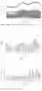
FIG. 1 shows results of optimal scheduling for peak regulation of a cascade hydro-photovoltaic complementary power generation system according to an example of the present disclosure;
FIG. 2 shows results of a unit commitment of a No. 1 hydro-power station in a cascade hydro-power station group according to an example of the present disclosure;
FIG. 3 shows results of a unit commitment of a No. 2 hydro-power station in a cascade hydro-power station group according to an example of the present disclosure; and
FIG. 4 shows results of a unit commitment of a No. 3 hydro-power station in a cascade hydro-power station group according to an example of the present disclosure.
SPECIFIC EMBODIMENTS
The present disclosure is further described below. The following examples are used only to illustrate technical solutions of the present disclosure more clearly and cannot be used to limit the scope of protection of the present disclosure.
The present disclosure provides an optimal scheduling method for peak regulation of a cascade hydro-photovoltaic complementary power generation system. The method includes the following steps:
-
- 1) an objective function of optimal scheduling for peak regulation of the cascade hydro-photovoltaic complementary power generation system is established;
- 2) specific information of a cascade hydro-power station and a photovoltaic power station is acquired, and a cascade hydro-power constraint condition considering a unit commitment and a photovoltaic power station output constraint condition considering uncertainty are established;
- 3) linear processing is performed on the constraint condition so as to establish a mixed integer linear model of optimal scheduling for peak regulation of the cascade hydro-photovoltaic complementary power generation system; and
- 4) the mixed integer linear model of optimal scheduling for peak regulation of a cascade hydro-photovoltaic complementary power generation system is solved, so as to obtain a scheduling solution for the cascade hydro-photovoltaic complementary power generation system.
Specifically, the step that an objective function of optimal scheduling for peak regulation of the cascade hydro-photovoltaic complementary power generation system is established includes the following step:
a minimized maximum residual load of a receiving-end grid is taken as the objective function:
min f = max ( P load ( t ) - ∑ i = 1 N h ∑ g = 1 G i P i , g ( t ) - P s e ( t ) ) , ∀ t ∈ T
where Pload(t) is a load (MW) at moment t; Pi,g(t) is active power output (MW) of a gth generating unit in an ith cascade hydro-power station at the moment t; Pse(t) is generating power (MW) of a photovoltaic power station at the moment t; T is a total time period of a scheduling period; Nh is the total number of cascade hydro-power stations, and 1≤i≤Nh; and Gi is the number of generating units involved in the ith cascade hydro-power station, and 1≤g≤Gi. Specifically, the step that a cascade hydro-power constraint condition considering a unit commitment and a photovoltaic power station output constraint condition considering uncertainty are established includes the following steps:
a photovoltaic power station output constraint is established as:
Pse(t)=Ps(t)+{circumflex over (P)}s(t)
{circumflex over (P)}sL(t)≤{circumflex over (P)}s(t)≤{circumflex over (P)}sU(t)
where Ps(t) is an expected value (MW) of the generating power of the photovoltaic power station at the moment t; {circumflex over (P)}s(t) is a power deviation (MW) of the photovoltaic power station at the moment t; Ps(t) and PS(t) may be obtained on the basis of historical data; and {circumflex over (P)}sL(t), {circumflex over (P)}sU(t) are a lower limit and an upper limit (MW) of the power deviation at the moment t, respectively.
a cascade hydro-power constraint considering the unit commitment is established, which includes:
a hydro-power unit output constraint:
Pi,g(t)=ηi,gHi(t)qi,g(t)
ui,g(t)Pi,gmin≤Pi,g(t)≤ui,g(t)Pi,gmax
where ηi,g is a hydro-power conversion coefficient of the gth generating unit in the ith cascade hydro-power station; Hi(t) is a power generation water head (m) of a unit in the ith cascade hydro-power station at the moment t; qi,g(t) is a power generation flow (m3/s) of the gth generating unit in the ith cascade hydro-power station at the moment t; Pi,gmin and Pi,gmax are a lower limit and an upper limit of the active power output of the gth generating unit in the ith cascade hydro-power station respectively; and ui,g(t) is an operating state variable of the gth generating unit in the ith cascade hydro-power station, and if the generating unit is activated, ui,g(t) is 1, and otherwise, ui,g(t) is 0;
a hydro-power unit vibration zone limit constraint:
(Pi,g(t)−Pi,gk)(Pi,g(t)−Pi,gk)≥0
where Pi,gk and Pi,gk are upper and lower output limits (MW) of a kth vibration zone of the gth generating unit in the ith cascade hydro-power station, respectively;
a hydro-power unit climbing ability limit constraint:
−ΔPi,g≤Pi,g(t+1)−Pi,g(t)≤ΔPi,g
where ΔPi,g is a climbing ability (MW/h) of the gth generating unit in the ith cascade hydro-power station;
a hydro-power unit on/off and minimum on/off duration constraint:
y i , g ( t ) - y ˜ i , g ( t ) = u i , g ( t ) - u i , g ( t - 1 ) y i , g ( t ) + y ˜ i , g ( t ) ≤ 1 y i , g ( t ) + ∑ l = t + 1 max { t + α i , g - 1 , T } y ˜ i , g ( l ) ≤ 1 y ˜ i , g ( t ) + ∑ l = t + 1 max { t + β i , g - 1 , T } y i , g ( l ) ≤ 1 y i , g ( t ) , y ˜ i , g ( t ) ∈ { 0 , TagBox[",", "NumberComma", Rule[SyntaxForm, "0"]] 1 }
where yi,g(t) and {tilde over (y)}i,g(t) are on and off operational variables of the gth generating unit in the ith cascade hydro-power station at moment t, respectively, and if the generating unit is activated, yi,g(t) is 1, and otherwise yi,g(t) is 0; if the generating unit is deactivated, {tilde over (y)}i,g(t) is 1, and otherwise, {tilde over (y)}i,g(t) is 0; and αi,g and βi,g are minimum on duration and minimum off duration of the gth generating unit in the ith cascade hydro-power station, respectively;
a hydro-power unit power generation flow constraint:
ui,g(t)qi,gmin≤qi,g(t)≤ui,g(t)gi,gmax
where qi,gmin and qi,gmax are upper and lower limits (m3/s) of a power generation flow of the gth generating unit in the ith cascade hydro-power station, respectively;
an abandoned water flow constraint:
0≤si(t)≤simax
where si(t) is a total abandoned water flow (m3/s) of the ith cascade hydro-power station at the moment t, and simax is the upper limit (m3/s) of an abandoned water flow of the ith cascade hydro-power station;
a reservoir water level constraint:
Zimin≤Zi(t)≤Zimax
where Zi(t) is a water level (m) of the reservoir corresponding to the ith cascade hydro-power station at the moment t; and Zimin and Zimax are a lower limit and an upper limit of the water level of the reservoir corresponding to the ith cascade hydro-power station, respectively, and a dead water level and a normal water level of the reservoir are taken separately;
a cascade water flow balance constraint:
V i ( t ) = V i ( t - 1 ) + [ I i ( t ) + ∑ g q i - 1 , g ( t - τ i - 1 ) + s i - 1 ( t - τ i - 1 ) - ∑ g q i , g ( t ) - s i ( t ) ] Δ t
where Vi(t) is a water storage capacity (m3) of the reservoir corresponding to the ith cascade hydro-power station at the moment t; Ii(t) is a natural incoming water flow (m3/s) of the ith cascade hydro-power station at the moment t; τi-1 is a time-lag (h) of water flow between an i−1st cascade hydro-power station and the ith cascade hydro-power station; and Δt is a length (s) of a period in the scheduling period;
a water level-reservoir capacity relationship constraint:
Zi(t)=ƒ(Vi(t))
where the function relationship may be obtained approximately by establishing a piecewise linear function according to actual data of the water level-reservoir capacity;
a tail water level-discharge flow relationship constraint:
Z i d ( t ) = f ( ∑ g q i , g ( t ) + s i ( t ) )
where Zid(t) is a tail water level (m) of the reservoir corresponding to the ith cascade hydro-power station at the moment t, and the function relationship is obtained according to the actual data of the reservoir; and
a water head constraint:
H i ( t ) = 1 2 [ Z i ( t ) + Z i ( t - 1 ) ] - Z i d ( t ) H i min ≤ H i ( t ) ≤ H i max
where Himin and Himax are the lower limit and upper limit (m) of the power generation water head of the generating unit in the ith cascade hydro-power station, respectively.
Specifically, the step that linear processing is performed on the constraint condition so as to establish a mixed integer linear model of optimal scheduling for peak regulation of the cascade hydro-photovoltaic complementary power generation system includes the following step:
linear processing is performed on the hydro-power unit output constraint, the unit vibration zone limit constraint, the water level-reservoir capacity relationship constraint and the tail water level-discharge flow relationship constraint separately.
1) The hydro-power unit output constraint is converted, by using a McCormick convex envelope relaxation method, into the following linear constraints:
Pi,g(t)≥ηi,g(qi,gmin(t)+Himinqi,g(t)−qi,gminHimin)
Pi,g(t)≥ηi,g(qi,gmaxHi(t)+Himaxqi,g(t)−qi,gmaxHimax)
Pi,g(t)≤ηi,g(qi,gminHi(t)+Himaxqi,g(t)−qi,g(t)−qi,gminHimax)
Pi,g(t)≤ηi,g(qi,gmaxHi(t)+Himinqi,gmaxHimin)
2) Linear processing is performed on the unit vibration zone limit constraint as follows:
∑ k = 1 K + 1 z i , g k ( t ) = u i , g ( t ) ∑ k = 1 K + 1 z i , g k ( t ) P _ safe , i , g k ≤ P i , g ( t ) ≤ ∑ k = 1 K + 1 z i , g k ( t ) P _ safe , i , g k
where K is the number of vibration zones of the gth generating unit in the ith cascade hydro-power station; K+1 is the number of safe operating zones of the gth generating unit in the ith cascade hydro-power station; zi,gk(t) is an indicator variable; if output of the gth generating unit in the ith cascade hydro-power station at the moment t is within a kth safe operating zone, zi,gk(t) is 1, and otherwise, zi,gk(t) is 0; Psafe,i,gk and Psafe,i,gk are upper and lower limits (MW) of the kth safe operating zone of the gth generating unit in the ith cascade hydro-power station respectively, and satisfy Psafe,i,g=Pi,gmin, Psafe,i,g=Pi,gmin, Psafe,i,gk=Pi,gk and Psafe,i,gK+1=Pi,gmax.
3) Piecewise linear processing is performed on the water level-reservoir capacity relationship constraint and the tail water level-discharge flow relationship constraint. The mixed integer linear model of optimal scheduling for peak regulation of the cascade hydro-photovoltaic complementary power generation system is solved, so as to obtain a scheduling solution for the cascade hydro-photovoltaic complementary power generation system.
Specifically, the mixed integer linear model of optimal scheduling for peak regulation of the cascade hydro-photovoltaic complementary power generation system is solved by using a CPLEX12.9 solver, so as to obtain the scheduling solution for the cascade hydro-photovoltaic complementary power generation system, that is, the active power output Pi,g(t) of the generating unit in the cascade hydro-power station at the moment t.
EXAMPLES
Examples of the present disclosure involve a photovoltaic power station and a cascade hydro-power station group consisting of 3 hydro-power stations. Firstly, the objective function of the optimal scheduling for peak regulation of the cascade hydro-photovoltaic complementary power generation system is established as follows:
min f = max ( P load ( t ) - ∑ i = 1 N h ∑ g = 1 G i P i , g ( t ) - P s e ( t ) ) , ∀ t ∈ T
where Pload(t) is a load (MW) at moment t; Pi,g(t) is active power output (MW) of a gth generating unit in an ith cascade hydro-power station at moment t; Pse(t) is generating power (MW) of a photovoltaic power station at the moment t; T is a total time period of a scheduling period; Nh is the total number of cascade hydro-power stations, and 1≤i≤Nh; and Gi is the total number of generating units contained in the ith cascade hydro-power station, and 1≤g≤Gi. The values of Pload(t) are shown in Table 1:
| TABLE 1 |
| System load |
| Time | 1 | 2 | 3 | 4 | 5 | 6 | 7 | 8 | 9 | 10 | 11 | 12 |
| period | ||||||||||||
| Pload(t) | 2,134 | 2,026 | 1,932 | 1,960 | 1,879 | 1,933 | 1,979 | 2,180 | 2,381 | 2,538 | 2,639 | 2,788 |
| (MW) | ||||||||||||
| Time | 13 | 14 | 15 | 16 | 17 | 18 | 19 | 20 | 21 | 22 | 23 | 24 |
| period | ||||||||||||
| Pload(t) | 2,627 | 2,568 | 2,482 | 2,444 | 2,500 | 2,564 | 2,757 | 2,798 | 2,793 | 2,756 | 2,562 | 2,252 |
| (MW) | ||||||||||||
Then, the specific information of the cascade hydro-power station and photovoltaic power station is acquired, and the constraint condition of optimal scheduling for peak regulation of the cascade hydro-photovoltaic complementary power generation system is established as follows:
1) A photovoltaic power station output constraint is established:
Pse(t)=Ps(t)+{circumflex over (P)}s(t)
{circumflex over (P)}sL(t)≤{circumflex over (P)}s(t)≤{circumflex over (P)}sU(t)
where Ps(t) is an expected value (MW) of the generating power of the photovoltaic power station at the moment t; {circumflex over (P)}s(t) is a power deviation (MW) of the photovoltaic power station at the moment t; and {circumflex over (P)}sL(t), {circumflex over (P)}sU(t) are the lower limit and upper limit (MW) of the power deviation at the moment t, respectively.
photovoltaic output parameters are shown in Table 2:
| TABLE 2 |
| Photovoltaic output |
| Time | Ps(t) | {circumflex over (P)}sL(t) | {circumflex over (P)}sU(t) | |
| period | (MW) | (MW) | (MW) | |
| 1 | 0 | 0 | 0 | |
| 2 | 0 | 0 | 0 | |
| 3 | 0 | 0 | 0 | |
| 4 | 0 | 0 | 0 | |
| 5 | 120 | −79.8 | 56.7 | |
| 6 | 130 | −87.5 | 51.1 | |
| 7 | 170 | −95.2 | 51.1 | |
| 8 | 240 | −75.6 | 34.3 | |
| 9 | 320 | −85.4 | 28 | |
| 10 | 370 | −119.7 | 19.6 | |
| 11 | 380 | −109.9 | 22.4 | |
| 12 | 430 | −135.8 | 14 | |
| 13 | 430 | −141.4 | 14 | |
| 14 | 410 | −135.8 | 15.4 | |
| 15 | 360 | −107.8 | 35.7 | |
| 16 | 300 | −86.1 | 45.5 | |
| 17 | 230 | −81.9 | 53.2 | |
| 18 | 230 | −89.6 | 40.6 | |
| 19 | 140 | −83.3 | 37.1 | |
| 20 | 100 | −67.9 | 60.2 | |
| 21 | 0 | 0 | 0 | |
| 22 | 0 | 0 | 0 | |
| 23 | 0 | 0 | 0 | |
| 24 | 0 | 0 | 0 | |
2) A hydro-power unit output constraint is established:
Pi,g(t)=ηi,gHi(t)qi,g(t)
ui,g(t)Pi,gmin≤Pi,g(t)≤ui,g(t)Pi,gmax
where ηi,g is a hydro-power conversion coefficient of the gth generating unit in the ith cascade hydro-power station; Hi(t) is a power generation water head (m) of a unit in the ith cascade hydro-power station at the moment t; qi,g(t) is a power generation flow (m3/s) of the gth generating unit in the ith cascade hydro-power station at the moment t; Pi,gmin and Pi,gmax are a lower limit and an upper limit of the active power output of the gth generating unit in the ith cascade hydro-power station, respectively; and ui,g(t) is an operating state variable of the gth generating unit in the ith cascade hydro-power station, and if the generating unit is activated, ui,g(t) is 1, and otherwise, ui,g(t) is 0.
Relevant parameters of the cascade hydro-power station are shown in Table 3:
| TABLE 3 |
| Relevant parameters of the cascade hydro-power station |
| Hydro- | Single unit | Minimum | ||||||
| power | Maximum | Minimum | Unit | maximum | on/off | |||
| station | Installed | water head | water head | vibration | generation | duration | Dead water | Normal water |
| number | capacity(MW) | (m) | (m) | zone (MW) | flow (m3/s) | (h) | level (m) | level (m) |
| 1 | 4*460 | 203 | 145 | 0~80, 150~300 | 257 | 2 | 350 | 400 |
| 2 | 4*300 | 121.5 | 80.7 | 80~180 | 328 | 2 | 180 | 200 |
| 3 | 3*90 | 40 | 22.3 | 0~20 | 291 | 2 | 78 | 80 |
3) A hydro-power unit vibration zone limit constraint is established:
(Pi,g(t)−Pi,gk)(Pi,g(t)−Pi,gk)≥0
where Pi,gk and Pi,gk are upper and lower output limits (MW) of a kth vibration zone of the gth generating unit in the ith cascade hydro-power station, respectively.
4) A hydro-power unit climbing ability limit constraint is established:
−ΔPi,g≤Pi,g(t+1)−Pi,g(t)≤ΔPi,g
where −ΔPi,g is a climbing ability (MW/h) of the gth generating unit in the ith cascade hydro-power station.
5) A hydro-power unit on/off and minimum on/off duration constraint is established is established:
y i , g ( t ) - y ˜ i , g ( t ) = u i , g ( t ) - u i , g ( t - 1 ) y i , g ( t ) + y ˜ i , g ( t ) ≤ 1 y i , g ( t ) + ∑ l = t + 1 max { t + α i , g - 1 , T } y ˜ i , g ( l ) ≤ 1 y ˜ i , g ( t ) + ∑ l = t + 1 max { t + β i , g - 1 , T } y i , g ( l ) ≤ 1 y i , g ( t ) , y ˜ i , g ( t ) ∈ { 0 , TagBox[",", "NumberComma", Rule[SyntaxForm, "0"]] 1 }
where yi,g(t) and yi,g(t) are on and off operational variables of the gth generating unit in the ith cascade hydro-power station at the moment t, respectively, and if the generating unit is activated, yi,g(t) is 1, and otherwise, yi,g(t) is 0; if the generating unit is deactivated, {tilde over (y)}i,g(t) is 1, and otherwise, {tilde over (y)}i,g(t) is 0; and αi,g and βi,g are minimum on duration and minimum off duration of the gth generating unit in the ith cascade hydro-power station, respectively.
6) A hydro-power unit power generation flow limit constraint is established:
ui,g(t)qi,gmin≤qi,g(t)≤ui,g(t)gi,gmax
where qi,gmin and qi,gmax are upper and lower limits (m3/s) of the power generation flow of the gth generating unit in the ith cascade hydro-power station, respectively.
7) An abandoned water flow constraint is established:
0≤si(t)≤simax
where si(t) is a total abandoned water flow (m3/s) of the ith cascade hydro-power station at the moment t; and simax is the upper limit (m3/s) of the abandoned water flow of the ith cascade hydro-power station.
8) A reservoir water level constraint is established:
Zimin≤Zi(t)≤Zimax
where Zi(t) is a water level (m) of the reservoir corresponding to the ith cascade hydro-power station at the moment t; and Zimin and Zimax are a lower limit and an upper limit of the water level of the reservoir corresponding to the ith cascade hydro-power station respectively, and a dead water level and a normal water level of the reservoir are taken separately.
9) A cascade water flow balance constraint is established:
V i ( t ) = V i ( t - 1 ) + [ I i ( t ) + ∑ g q i - 1 , g ( t - τ i - 1 ) + s i - 1 ( t - τ i - 1 ) - ∑ g q i , g ( t ) - s i ( t ) ] Δ t
where Vi(t) is a water storage capacity (m3) of the reservoir corresponding to the ith cascade hydro-power station at the moment t; Ii(t) is a natural incoming water flow (m3/s) of the ith cascade hydro-power station at the moment t; τi-1 is a time-lag (h) of a water flow between an i−1st cascade hydro-power station and the ith cascade hydro-power station; and Δt is a length (s) of a period in the scheduling period.
10) A water level-reservoir capacity relationship constraint is established:
Zi(t)=ƒ(Vi(t))
11) A tail water level-discharge flow relationship constraint is established:
Z i d ( t ) = f ( ∑ g q i , g ( t ) + s i ( t ) )
where Zid(t) is a tail water level (m) of the reservoir corresponding to the ith cascade hydro-power station at the moment t.
12) A water head constraint is established:
H i ( t ) = 1 2 [ Z i ( t ) + Z i ( t - 1 ) ] - Z i d ( t ) H i min ≤ H i ( t ) ≤ H i max
where Himin and Himax are a lower limit and an upper limit (m) of the power generation water head of the generating unit in the ith cascade hydro-power station, respectively.
Then, linear processing is performed on the constraint, and a mixed integer linear model of optimal scheduling for peak regulation of the cascade hydro-photovoltaic complementary power generation system is established as follows:
1) the hydro-power unit output constraint is converted, by using a McCormick convex envelope relaxation method, into the following linear constraints:
Pi,g(t)≥ηi,g(qi,gmin(t)+Himinqi,g(t)−qi,gminHimin)
Pi,g(t)≥ηi,g(qi,gmaxHi(t)+Himaxqi,g(t)−qi,gmaxHimax)
Pi,g(t)≤ηi,g(qi,gminHi(t)+Himaxqi,g(t)−qi,g(t)−qi,gminHimax)
Pi,g(t)≤ηi,g(qi,gmaxHi(t)+Himinqi,gmaxHimin)
2) Linear processing is performed on the unit vibration zone limit constraint as follows:
∑ k = 1 K + 1 z i , g k ( t ) = u i , g ( t ) ∑ k = 1 K + 1 z i , g k ( t ) P _ safe , i , g k ≤ P i , g ( t ) ≤ ∑ k = 1 K + 1 z i , g k ( t ) P _ safe , i , g k
where K is the number of vibration zones of the gth generating unit in the ith cascade hydro-power station; K+1 is the number of safe operating zones of the gth generating unit in the ith cascade hydro-power station; Zi,gk(t) is an indicator variable; if the output of the gth generating unit in the ith cascade hydro-power station at the moment t is within a kth safe operating zone, zi,gk(t) is 1, and otherwise, zi,gk(t) is 0; Psafe,i,gk and Psafe,i,gk are upper and lower limits (MW) of the kth safe operating zone of the gth generating unit in the cascade hydro-power station respectively, and satisfy Psafe,i,g1=Pi,gmin, Psafe,i,gk=Pi,gK+1, Psafe,i,gk=Pi,gk and Psafe,i,gK+1=Pi,gmax.
3) Piecewise linear processing is performed on the water level-reservoir capacity relationship constraint and the tail water level-discharge flow relationship constraint. Finally, the mixed integer linear model of optimal scheduling for peak regulation of the cascade hydro-photovoltaic complementary power generation system is solved by using a CPLEX12.9 solver, so as to obtain a scheduling solution for the cascade hydro-photovoltaic complementary power generation system, as shown in FIG. 1 and Table 4. FIG. 2, FIG. 3 and FIG. 4 show output results of each unit of a No. 1 hydro-power station, a No. 2 hydro-power station and a No. 3 hydro-power station in a cascade hydro-power station group, respectively.
| TABLE 4 |
| Scheduling solution of a unit commitment of a cascade hydro- |
| photovoltaic complementary power generation system |
| Output of each unit of | Output of each unit of | Output of each unit of | |
| hydro-power station 1 (MW) | hydro-power station 2 (MW) | hydro-power station 3 (MW) |
| Moment | 1-1# | 1-2# | 1-3# | 1-4# | 2-1# | 2-2# | 2-3# | 2-4# | 3-1# | 3-2# | 3-3# |
| 1 | 80 | 0 | 93 | 415 | 249 | 0 | 60 | 0 | 26 | 0 | 79 |
| 2 | 416 | 0 | 0 | 138 | 264 | 0 | 0 | 0 | 0 | 0 | 77 |
| 3 | 378 | 0 | 0 | 80 | 265 | 0 | 0 | 0 | 0 | 0 | 77 |
| 4 | 336 | 0 | 0 | 150 | 266 | 0 | 0 | 0 | 0 | 26 | 52 |
| 5 | 310 | 0 | 0 | 0 | 242 | 0 | 0 | 0 | 0 | 52 | 26 |
| 6 | 328 | 0 | 0 | 0 | 266 | 0 | 0 | 0 | 52 | 26 | 0 |
| 7 | 0 | 0 | 0 | 335 | 265 | 0 | 0 | 0 | 77 | 0 | 0 |
| 8 | 0 | 80 | 0 | 388 | 264 | 0 | 0 | 0 | 0 | 0 | 77 |
| 9 | 0 | 132 | 0 | 416 | 300 | 0 | 0 | 0 | 0 | 0 | 81 |
| 10 | 359 | 0 | 0 | 300 | 300 | 0 | 0 | 0 | 26 | 26 | 26 |
| 11 | 300 | 0 | 302 | 80 | 271 | 0 | 0 | 0 | 77 | 26 | 72 |
| 12 | 80 | 368 | 300 | 0 | 300 | 0 | 0 | 0 | 77 | 26 | 77 |
| 13 | 300 | 412 | 0 | 0 | 276 | 0 | 0 | 0 | 26 | 26 | 26 |
| 14 | 80 | 390 | 0 | 0 | 300 | 0 | 0 | 180 | 0 | 52 | 26 |
| 15 | 146 | 0 | 0 | 416 | 0 | 0 | 0 | 274 | 0 | 78 | 78 |
| 16 | 136 | 0 | 0 | 416 | 0 | 300 | 0 | 60 | 0 | 74 | 26 |
| 17 | 419 | 0 | 0 | 0 | 0 | 300 | 0 | 300 | 41 | 0 | 79 |
| 18 | 412 | 300 | 0 | 0 | 0 | 80 | 0 | 277 | 79 | 0 | 55 |
| 19 | 300 | 398 | 0 | 0 | 0 | 248 | 180 | 180 | 77 | 26 | 77 |
| 20 | 301 | 80 | 300 | 300 | 0 | 300 | 60 | 0 | 75 | 75 | 75 |
| 21 | 408 | 0 | 408 | 140 | 0 | 300 | 180 | 0 | 75 | 75 | 75 |
| 22 | 150 | 0 | 80 | 414 | 300 | 0 | 300 | 181 | 76 | 48 | 76 |
| 23 | 0 | 411 | 332 | 0 | 206 | 0 | 80 | 180 | 75 | 75 | 72 |
| 24 | 0 | 300 | 150 | 0 | 180 | 0 | 228 | 180 | 84 | 0 | 0 |
Those skilled in the art should understand that the examples of the present application can be provided as methods, systems or computer program products. Accordingly, the present application can be in the form of entirely hardware examples, entirely software examples, or examples of a combination of software and hardware. Further, the present application can be in the form of computer program products implemented on one or more computer-usable storage media (including, but not limited to, a disk memory, a compact disk read-only memory (CD-ROM), an optical memory, etc.) including computer-usable program codes.
The present application is described with reference to flow charts and/or block diagrams of methods, devices (systems) and computer program products according to the examples of the present application. It should be understood that each flow and/or block in the flow chart and/or block diagram and combinations of the flow and/or block in the flow chart and/or block diagram, can be implemented by computer program instructions. These computer program instructions can be provided for a processor of a general-purpose computer, a special-purpose computer, an embedded processor, or other programmable data processing devices, so as to generate a machine, so that instructions executed by the processor of computers or other programmable data processing devices generate an apparatus for performing a function specified in one or more flows of a flow chart and/or one or more blocks of a block diagram. These computer program instructions can also be stored in a computer-readable memory capable of directing computers or other programmable data processing devices to operate in a particular manner, so that instructions stored in the computer-readable memory produce a manufactured product including a command apparatus that implements the function specified in one or more flows of a flow chart and/or one or more blocks of a block diagram.
These computer program instructions can also be loaded into computers or other programmable data processing devices, so that a series of operational steps are executed on the computer or other programmable devices, so as to produce computer-implemented processing, so that instructions executed on the computer or other programmable devices provide steps for implementing the function specified in one or more flows of a flow chart and/or one or more blocks of a block diagram.
Finally, it should be noted that the examples described above are only used to illustrate technical solutions of the present disclosure, and not to limit the present disclosure. Although the present disclosure is described in detail with reference to the above examples, those ordinary skilled in the art should understand that specific embodiments of the present disclosure can still be modified or replaced equivalently. These modifications or equivalent replacements, within the spirit and scope of the present disclosure, should fall within the scope of protection of the claims of the present disclosure.
Claims
What is claimed is:1. An optimal scheduling method for peak regulation of a cascade hydro-photovoltaic complementary power generation system, comprising:
establishing an objective function of optimal scheduling for peak regulation of the cascade hydro-photovoltaic complementary power generation system; and establishing a cascade hydro-power constraint condition considering a unit commitment and a photovoltaic power station output constraint condition considering uncertainty;
performing linear processing on the constraint condition, and establishing a mixed integer linear model of optimal scheduling for peak regulation of the cascade hydro-photovoltaic complementary power generation system on the basis of the objective function and the constraint condition after linear processing; and
solving the mixed integer linear model of optimal scheduling for peak regulation of the cascade hydro-photovoltaic complementary power generation system so as to obtain a scheduling solution for the cascade hydro-photovoltaic complementary power generation system.
2. The optimal scheduling method for peak regulation of a cascade hydro-photovoltaic complementary power generation system according to claim 1, wherein the establishing an objective function of optimal scheduling for peak regulation of the cascade hydro-photovoltaic complementary power generation system comprises:
taking a minimized maximum residual load of a receiving-end grid during a scheduling period as the objective function:
min f = max ( P load ( t ) - ∑ i = 1 N h ∑ g = 1 G i P i , g ( t ) - P s e ( t ) ) , ∀ t ∈ T
wherein ƒ is a maximum residual load of the receiving-end grid; Pload(t) is a load at moment t; Pi,g(t) is active output of a gth generating unit in an ith cascade hydro-power station at the moment t; Pse(t) is generating power of the photovoltaic power station at the moment t; T is a total time period of the scheduling period; Nh is the total number of cascade hydro-power stations; and Gi is the number of generating units involved in the ith, cascade hydro-power station.
3. The optimal scheduling method for peak regulation of a cascade hydro-photovoltaic complementary power generation system according to claim 2, wherein the establishing a cascade hydro-power constraint condition considering a unit commitment and a photovoltaic power station output constraint condition considering uncertainty comprises:
establishing a photovoltaic power station output constraint as:
Pse(t)=Ps(t)+{circumflex over (P)}s(t)
{circumflex over (P)}sL(t)≤{circumflex over (P)}s(t)≤{circumflex over (P)}sU(t)
wherein Ps(t) is an expected value of the generating power of the photovoltaic power station at the moment t; {circumflex over (P)}s(t) is a power deviation of the photovoltaic power station at the moment t; and {circumflex over (P)}sL(t), {circumflex over (P)}sU(t) are a lower limit and an upper limit of the power deviation at the moment t, respectively; and
establishing a cascade hydro-power constraint considering the unit commitment,
which comprises:
a hydro-power unit output constraint:
Pi,g(t)=ηi,gHi(t)qi,g(t)
ui,g(t)Pi,gmin≤Pi,g(t)≤ui,g(t)Pi,gmax
wherein ηi,g is a hydro-power conversion coefficient of the gth generating unit in the ith, cascade hydro-power station; Hi(t) is a power generation water head of a unit in the ith, cascade hydro-power station at the moment t; qi,g(t) is a power generation flow of the gth generating unit in the ith, cascade hydro-power station at the moment t; Pi,gmin and Pi,gmax are a lower limit and an upper limit of active power output of the gth generating unit in the ith cascade hydro-power station, respectively; and ui,g(t) is an operating state variable of the gth generating unit in the ith cascade hydro-power station, wherein if the generating unit is activated, ui,g(t) is 1, and otherwise, ui,g(t) is 0;
a hydro-power unit vibration zone limit constraint:
(Pi,g(t)−Pi,gk)(Pi,g(t)−Pi,gk)≥0
wherein Pi,gk and Pi,gk are upper and lower output limits of a kth vibration zone of the gth generating unit in the ith, cascade hydro-power station, respectively;
a hydro-power unit climbing ability limit constraint:
−ΔPi,g≤Pi,g(t+1)−Pi,g(t)≤ΔPi,g
wherein ΔPi,g is a climbing ability of the gth generating unit in the ith cascade hydro-power station;
a hydro-power unit on/off and minimum on/off duration constraint:
y i , g ( t ) - y ~ i , g ( t ) = u i , g ( t ) - u i , g ( t - 1 ) y i , g ( t ) - y ~ i , g ( t ) ≤ 1 y i , g ( t ) + ∑ l = t + 1 max { t + α i , g - 1 , T } y ~ i , g ( l ) ≤ 1 y ~ i , g ( t ) + ∑ l = t + 1 max { t + β i , g - 1 , T } y i , g ( l ) ≤ 1 y i , g ( t ) , y ~ i , g ( t ) ∈ { 0 , TagBox[",", "NumberComma", Rule[SyntaxForm, "0"]] 1 }
wherein yi,g(t) and {tilde over (y)}i,g(t) are on and off operational variables of the gth generating unit in the ith cascade hydro-power station at the moment t, respectively, wherein if the generating unit is activated, yi,g(t) is 1, and otherwise, yi,g(t) is 0; if the generating unit is deactivated, {tilde over (y)}i,g(t) is 1, and otherwise, {tilde over (y)}i,g(t) is 0; and αi,g and βi,g are minimum on duration and minimum off duration of the gth generating unit in the ith, cascade hydro-power station, respectively;
a hydro-power unit power generation flow limit constraint:
ui,g(t)qi,gmin≤qi,g(t)≤ui,g(t)gi,gmax
wherein qi,gmin and qi,gmax are upper and lower limits of the power generation flow of the gth generating unit in the ith cascade hydro-power station, respectively;
an abandoned water flow limit constraint:
0≤si(t)≤simax
wherein si(t) is a total abandoned water flow (m3/s) of the ith cascade hydro-power station at the moment t, and simax is the upper limit of an abandoned water flow of the ith cascade hydro-power station;
a reservoir water level limit constraint:
Zimin≤Zi(t)≤Zimax
wherein Zi(t) is a water level of a reservoir corresponding to the ith cascade hydro-power station at the moment t; Zimin and Zimax are a lower limit and an upper limit of the water level of the reservoir corresponding to the ith cascade hydro-power station, respectively, and a dead water level and a normal water level of the reservoir are taken separately;
a cascade water flow balance constraint:
V i ( t ) = V i ( t - 1 ) + [ I i ( t ) + ∑ g q i - 1 , g ( t - τ i - 1 ) + s i - 1 ( t - τ i - 1 ) - ∑ g q i , g ( t ) - s i ( t ) ] Δ t
wherein Vi(t) is a water storage capacity of the reservoir corresponding to the ith cascade hydro-power station at the moment t; Ii(t) is a natural incoming water flow of the ith cascade hydro-power station at the moment t; τi-1 is a time lag of water flow between an i−1st cascade hydro-power station and the ith, cascade hydro-power station; and Δt is a length of a time period in the scheduling period;
a water level-reservoir capacity relationship constraint:
Zi(t)=ƒ(Vi(t))
a tail water level-discharge flow relationship constraint:
Z i d ( t ) = f ( ∑ g q i , g ( t ) + s i ( t ) )
wherein Zid(t) is a tail water level of the reservoir corresponding to the ith cascade hydro-power station at the moment t; and
a water head constraint:
H i ( t ) = 1 2 [ Z i ( t ) + Z i ( t - 1 ) ] - Z i d ( t ) H i min ≤ H i ( t ) ≤ H i max
wherein Himin and Himax are a lower limit and an upper limit of the power generation water head of the generating unit in the ith cascade hydro-power station, respectively.
4. The optimal scheduling method for peak regulation of a cascade hydro-photovoltaic complementary power generation system according to claim 3, wherein the performing linear processing on the constraint condition comprises:
converting, by using a McCormick convex envelope relaxation method, the hydro-power unit output constraint into the following linear constraints:
Pi,g(t)≥ηi,g(qi,gmin(t)+Himinqi,g(t)−qi,gminHimin)
Pi,g(t)≥ηi,g(qi,gmaxHi(t)+Himaxqi,g(t)−qi,gmaxHimax)
Pi,g(t)≤ηi,g(qi,gminHi(t)+Himaxqi,g(t)−qi,g(t)−qi,gminHimax)
Pi,g(t)≤ηi,g(qi,gmaxHi(t)+Himinqi,gmaxHimin)
performing linear processing on the unit vibration zone limit constraint as follows:
∑ k = 1 K + 1 z i , g k ( t ) = u i , g ( t ) ∑ k = 1 K + 1 z i , g k ( t ) P _ safe , ig k ≤ P i , g ( t ) ≤ ∑ k = 1 K + 1 z i , g k ( t ) P _ safe , i , g k
wherein K is the number of vibration zones of the gth generating unit in the ith, cascade hydro-power station; K+1 is the number of safe operating zones of the gth generating unit in the ith, cascade hydro-power station; zi,gk(t) is an indicator variable, and if output of the gth generating unit in the ith cascade hydro-power station at the moment t is within a kth safe operating zone, zi,gk(t) is 1, and otherwise, zi,gk(t) is 0; Psafe,i,gk and Psafe,i,gk are upper and lower limits of the kth safe operating zone of the gth generating unit in the ith cascade hydro-power station, respectively, and satisfy Psafe,i,gk=Pi,gmin, Psafe,i,gk=Pi,gk+1, Psafe,i,gk=Pi,gk and Psafe,i,gk=Pi,gmax; and
performing piecewise linear processing on the water level-reservoir capacity relationship constraint and tail water level-discharge flow relationship constraints separately.
5. The optimal scheduling method for peak regulation of a cascade hydro-photovoltaic complementary power generation system according to claim 4, wherein the solving the mixed integer linear model of optimal scheduling for peak regulation of the cascade hydro-photovoltaic complementary power generation system so as to obtain a scheduling solution for the cascade hydro-photovoltaic complementary power generation system comprises:
solving the mixed integer linear model of optimal scheduling for peak regulation of the cascade hydro-photovoltaic complementary power generation system by using a CPLEX12.9 solver, so as to obtain the active power output of each generating unit in the cascade hydro-power station at each moment.
Images & Drawings included:


Sources:
- United States Patent and Trademark Office - verify current appl. status at the USPTO↗
Recent applications in this class:
- » 20250172918 2025-05-29
MACHINE CONTROL UNIT, MACHINE TOOL, POWER CONSUMPTION CONTROL METHOD, AND COMPUTER-READABLE STORAGE MEDIUM - » 20250172917 2025-05-29
METHOD AND APPARATUS FOR OPTIMIZING SYSTEM ENERGY EFFICIENCY BASED ON AN INTEGRATED ENERGY REQUIREMENT, ELECTRONIC DEVICE, AND STORAGE MEDIUM - » 20250164955 2025-05-22
SYSTEMS AND METHODS FOR GENERATING A CONTINUOUS MUSIC SOUNDSCAPE USING AUTOMATIC COMPOSITION - » 20250164954 2025-05-22
VAPORIZER CONTROLS - » 20250155861 2025-05-15
METHOD FOR PREDICTING ELECTRIC ENERGY CONSUMPTION IN AN ELECTRIC GRID - » 20250138499 2025-05-01
THERMAL OPTIMIZATION FOR DATA CENTERS - » 20250130543 2025-04-24
Method for Determining System Excitation by at Least One Input Signal for Model-Based Control of a Technical System - » 20250123610 2025-04-17
AUTOMATED STRATEGY PLANNING FOR SEVERE WEATHER-DRIVEN PROACTIVE OUTAGE AND RESTORATION EVENTS IN A POWER GRID - » 20250123609 2025-04-17
SCADA WEB HMI SYSTEM - » 20250110461 2025-04-03
AUTOMATED EDGE DEVICE CONFIGURATION FOR BUILDING MANAGEMENT SYSTEMS