Rotating Control Device Clamping Mechanism
US20240093566A1
2024-03-21
18/517,974
2023-11-22
Smart Summary: A closure mechanism for a rotating control device used in managed pressure drilling, designed to securely install a bearing assembly into a body with an upper circular opening and outer edge. The closure collet features a top section with protruding shoulders and downward fingers that grip the body's outer edge, while a collet lock ring slides to secure the collet in place during operation. This invention ensures the bearing assembly is firmly inserted into the body for efficient drilling operations. 🚀 TL;DR
Abstract:
A closure arrangement for use on a rotating control device used during managed pressure drilling, said closure arrangement adapted for the installation of a bearing assembly adapted for insertion into a body, said body defining an upper circular opening and comprising an outer circumferential edge, said closure arrangement comprising:
-
- a closure collet comprising:
- a top section comprising an outwardly protruding shoulder and an inwardly protruding shoulder; and a plurality of spaced apart fingers extending downwardly therefrom forming a middle section and a bottom section of said collet; said fingers adapted to securely and removably fit around said outer circumferential edge of said body; and
- a collet lock ring adapted to slidingly move between a first position defined by the middle section of the closure collet and a second position proximate the bottom section of the closure collet; wherein, when the closure arrangement is in use, the bearing assembly is securely inserted into said body and the collet lock ring is secured around the bottom section of the closure collet.
- a closure collet comprising:
Applicant:
Interested in similar patents?
Get notified when new applications in this technology area are published.
Classification:
F16C33/7813 » CPC main
Parts of bearings; Special methods for making bearings or parts thereof; Sealings of ball or roller bearings with a diaphragm, disc, or ring, with or without resilient members suited for particular types of rolling bearings for tapered roller bearings
E21B33/085 » CPC further
Sealing or packing boreholes or wells; Surface sealing or packing; Wipers; Oil savers Rotatable packing means, e.g. rotating blow-out preventers
F16C19/548 » CPC further
Bearings with rolling contact, for exclusively rotary movement; Systems consisting of a plurality of bearings with rolling friction; Systems with spaced apart rolling bearings including at least one angular contact bearing with two angular contact rolling bearings in O-arrangement
F16C33/7886 » CPC further
Parts of bearings; Special methods for making bearings or parts thereof; Sealings of ball or roller bearings with a diaphragm, disc, or ring, with or without resilient members mounted outside the gap between the inner and outer races, e.g. sealing rings mounted to an end face or outer surface of a race
F16C33/78 IPC
Parts of bearings; Special methods for making bearings or parts thereof; Sealings of ball or roller bearings with a diaphragm, disc, or ring, with or without resilient members
E21B33/08 IPC
Sealing or packing boreholes or wells; Surface sealing or packing Wipers; Oil savers
F16C19/54 IPC
Bearings with rolling contact, for exclusively rotary movement Systems consisting of a plurality of bearings with rolling friction
Description
FIELD OF THE INVENTION
This invention relates to a rotating control device, more specifically to a new rotating control device assembly clamping mechanism.
BACKGROUND OF THE INVENTION
In the oil and gas industry, managed pressure drilling (MPD) is important in order to help in minimizing drilling hazards with pressure control. MPD involves actively controlling well pressure. By using a closed-loop system the operators using MPD can determine a well's downhole pressure limits and can also manage the annular pressure profile.
Rotating control devices (RCDs) create a pressure-tight barrier in the wellbore annulus that enables safe fluid containment and diversion, a vital defense against drilling hazards. As a critical element of managed pressure drilling (MPD) systems, RCDs provide an additional line of defense to protect oil rig personnel and equipment.
RCD devices provide an annular pressure seal in various diameter wells under standard temperature conditions. RCD devices enable drilling operations in managed pressure drilling to continue while isolating rig personnel from potentially harmful wellbore fluids and gases.
The flowline hub and clamp is the connection for attaching pipe work to the RCD for fluid to flow through. Previously this was done with either hammer unions or flanges. Flanges increase the overall high and/or width with additional machining required on the unit. Hammer unions will increase overall width and can be damaged easily and cause leaks. Flanges are difficult to install in the tight areas or some rigs as installing the studs is much more precise then the connections of a hammer union and hub and clamp. The main reasons therefore of this are to decrease overall height and width in a fashion that does not decrease the durability of the unit. The main point of the connection is relevant to the overall height of the entire assembly of the body and bearing assembly as well the overall outer diameter—these are two key factors which need to be taken into account when considering new designs.
Despite the available technologies to use with RCDs, there still exists a need for a clamping mechanism which facilitates the operational use of the RCD and can preferably increase the safety profile in installing RCDs.
The inventors have designed and developed a novel clamping mechanism (also referred to as a closure arrangement) for rotating control devices (RCDs) along with a novel hub attachment which greatly facilitates operations involving RCDs.
SUMMARY OF THE INVENTION
According to a first aspect of the present invention, there is provided a novel rotating control device (RCD) for use managed pressure devices used in drilling oil (and gas) wells. One of the advantages of the present invention is that it provides a quicker system allowing for the various pieces of a clamping and closure assembly to be attached much faster.
According to an aspect of the present invention, there is provided a closure arrangement for use on a rotating control device used during managed pressure drilling, said closure arrangement adapted for the installation of a bearing assembly adapted for insertion into a body, said body defining an upper circular opening and comprising an outer circumferential edge, said closure arrangement comprising:
-
- a closure collet comprising:
- a top section comprising an outwardly protruding shoulder and an inwardly protruding shoulder; and a plurality of spaced apart fingers extending downwardly therefrom forming a middle section and a bottom section of said collet; said fingers adapted to securely and removably fit around said outer circumferential edge of said body; and
- a collet lock ring adapted to slidingly move between a first position defined by the middle section of the closure collet and a second position proximate the bottom section of the closure collet; wherein, when the closure arrangement is in use, the bearing assembly is securely inserted into said body and the collet lock ring is secured around the bottom section of the closure collet.
- a closure collet comprising:
Preferably, the inwardly protruding shoulder of the closure collet is adapted to fit a complementary cavity located on said bearing assembly.
Preferably also, the closure collet comprises a single piece comprising an upper section itself comprising a solid upper ring, and a lower section comprising a plurality of flexible fingers integral with the upper section adapted to allow the expansion of the lower part over the outer circumferential edge of the body when inserting or removing the closure arrangement therefrom.
According to a preferred embodiment of the present invention, the lock ring comprises a solid piece comprising two or more ears adapted to attach lifting means. Preferably, the lifting means comprise commercially available eye bolts intended for lifting.
According to a preferred embodiment of the present invention, wherein the inwardly protruding shoulder of the collet is adapted to be inserted between a first piece and a second piece on the bearing assembly wherein the first piece is adjacent to the second piece and wherein the collet does not create a rotational lock to said bearing assembly.
According to a preferred embodiment of the present invention, upon installation, the bearing assembly is maintained in alignment with the body with anti-rotation pins.
According to a preferred embodiment of the present invention, the closure collet fingers further comprise a shallow inward facing taper adapted to engage with a shallow outward facing taper positioned on an upper outside circumferential edge of the body.
According to a preferred embodiment of the present invention, the closure collet is also adapted to expand over a lip located on the upper edge of the body.
Preferably, the closure collet and the body each comprise complimentary tapers adapted to mutually engage one another to guide and center the bearing assembly during the process of lowering the bearing assembly within the circular opening of the body.
Preferably, when the bearing assembly is fully seated in the body, the closure collet is secured to the body by fitting engagement of the upward facing tapered face on the bottom of the collet with the downward facing lower tapered face on the body.
According to a preferred embodiment of the present invention, the collet lock ring is adapted to freely move when located around the middle section of the closure collet and can slide downward to the bottom section of the closure collet until a downward facing taper on the inside of the lock ring is in engagement with an upward facing taper on the closure collet.
According to another aspect of the present invention, there is provided a method of securing a bearing assembly into a body during managed pressure drilling operations, said body having an upper circumferential opening defining a circular aperture, wherein said method comprises:
-
- providing a closure arrangement according to a preferred embodiment of the present invention;
- securing the collet to the bearing assembly;
- securing a lift sling to lifting hooks located on the collet ring;
- lifting the bearing assembly;
- aligning the bearing assembly over the circular aperture in the body;
- lowering the bearing assembly into the circular aperture in the body (2);
- aligning the anti-rotation pins with the corresponding openings in the bearing assembly;
- sliding the closure collet down to be secured around the bottom section of the collet by abutting a downward facing taper on the inside of the lock ring with an upward facing taper on the closure collet; and
- removing the lift sling from the hooks located on the collet ring.
Additional features and advantages of the invention will be set forth in the detailed description which follows, and in part will be readily apparent to the person skilled in the art from that description or recognized by practicing the invention as described herein, including the detailed description which follows, the claims, as well as the appended figures.
BRIEF DESCRIPTION OF THE FIGURES
The invention may be more completely understood in consideration of the following description of various embodiments of the invention in connection with the accompanying figures, in which:
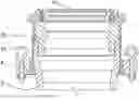
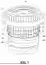
FIG. 1 is a side cross-sectional view of the clamping assembly according to a preferred embodiment of the present invention;
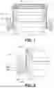
FIG. 2 is a close-up of a side cross-sectional view of the clamping assembly according to a preferred embodiment of the present invention; and
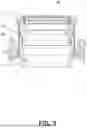
FIG. 3 is another side cross-sectional view of the clamping assembly according to a preferred embodiment of the present invention;
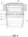
FIG. 4 is a side partially cross-sectional view of the clamping assembly according to a preferred embodiment of the present invention where the collet is positioned above the body;
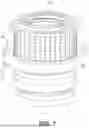
FIG. 5 is a perspective view of the clamping assembly according to a preferred embodiment of the present invention where the collet is positioned above the body;
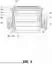
FIG. 6 is a side cross-sectional view of the clamping assembly according to a preferred embodiment of the present invention where the collet is positioned on the body and the collet ring is positioned around the bottom portion of the collet; and
FIG. 7 is a perspective view of the clamping assembly according to a preferred embodiment of the present invention where the collet is positioned on the body and the collet ring is positioned around the bottom portion of the collet.
DESCRIPTION OF A PREFERRED EMBODIMENT OF THE INVENTION
The clamping mechanism is preferably a collet which is viewable in FIGS. 1 and 2. The main benefits of the closure arrangement according to the present invention are that: no one has to climb onto the BOP stack to install or remove the bearing; and it does not require the use of hydraulics. The former is a clear safety advantage over other known devices and the latter relieves the amount of equipment required for the installation of an RCD.
According to a preferred embodiment of the present invention, the closure arrangement consists of 4 separate pieces: bearing assembly, body, closure collet, and collet lock ring.
FIGS. 1, 2 and 3 depict the collet lock ring captured between two pieces on the bearing assembly with clearance and are not rotationally locked. The outside top of the body has two different tapered faces which oppose each other (tapered in opposite directions). The upward facing taper is shallower than the downward facing one so the installation force is lower compared to the removal force. Preferably, the closure collet is a single piece with a solid upper ring, and the lower part consists of multiple flexible fingers integral to the upper part which allow the expansion of the lower part over the body. The lock ring is a solid piece with two ears to attach commercially available eye bolts intended for lifting.
Once everything is assembled, the lock ring cannot be removed from the closure collet due to an upward facing taper at the bottom and a shoulder at the top. Once installed inside the body as desired, the bearing assembly is rotationally locked to the body through the use of dowel pins which are press fit into the top face of the body. These pins engage in slots in the bottom face of the bearing assembly.
Installation Sequence
To install the closure arrangement according to a preferred embodiment of the present invention and illustrated in accompanying FIGS. 1, 2, 3, 4, 5, 6 and 7.
-
- 1) A two leg sling (not shown) is attached to the lift eyes (41) which are attached to the collet lock ring (4). When lifting, the collet lock ring (4) moves up freely and sits on the shoulder face of the closure collet (3). The entire bearing assembly is suspended from the lock ring.
- 2) The bearing assembly (10) is lowered into the body (2) and is rotated to the correct alignment to fit the anti-rotation pins (23). During lowering, the shallow downward facing taper (35a) on the closure collet engages on a shallow upward facing taper (21) on the outside of the body (2) and expands over the lip (24) on the body (2). Tapers on all parts guide the assembly to center as it is lowered. Another taper (35b) is adapted to fit against the body (2) at a lower position than the first inside taper (35a) located at the bottom portion of the fingers (32).
- 3) When the bearing assembly (10) is fully seated in the body (2), the closure collet (3) will be in a position which allows it to return to its natural position. In this position, the upward facing tapered face (232) on the bottom of the collet (3) engages a downward facing lower tapered face (22) on the body.
- 4) Lowering of the bearing assembly (10) is continued and the lock ring (4) freely moves downward on the closure collet beyond the upward facing taper (36) until the downward facing taper (34) on the inside of the lock ring (4) engages with an upward facing taper (42) on the closure collet. The bearing assembly (10) is now held in place in the body (2) since the lock ring (4) prevents the closure collet (3) from expanding.
- 5) The closure arrangement secures the bearing assembly to the body and the lift sling is removed. The unit is now ready for operation.
The removal can be effected by following these steps:
-
- 1) A two leg sling is attached to the lift eyes which are attached to the collet lock ring.
- 2) The lock ring is lifted, which will allow the collet fingers to expand over the body. The entire bearing assembly is now free to be removed.
- 3) The lock ring is lifted until it engages on the upper shoulder of the closure collet.
- 4) Lifting is continued, the closure collet fingers expand over the body. At this point, the entire bearing assembly is suspended.
- 5) Lifting is continued until the bearing unit is clear of the body. At this point, any service can be performed and the unit reinstalled.
FIGS. 5, 6 and 7 illustrate the advantage of having a collet with a plurality downward extending finger (32). When lined up with the body, the fingers (32) can be pressed down around the circumference (21) of the top portion (24) of the body (2) and positioned prior to the sliding of the collet ring thereon. This facilitates the task of installation of the closure arrangement onto the body. Moreover, preferably the fingers are shaped to accommodate the collet ring in a middle portion (32b) of the collet (32) when the latter is not installed securely to the body. The bottom portion (32c) of the collet basically is the section comprising the extremity of the fingers which, when properly positioned on the body allow the collet ring to slide into position around the bottom portion (32c) of the collet and be thereafter tightened to secure the closure arrangement onto the body (2).
According to a preferred embodiment of the present invention, each one of the fingers (32) is identical and comprises a top portion (32a) coinciding with the top portion of the collet (3), a middle section (32b) which is narrower and adapted to receive the collet ring and allow such to slide up and down in the installation process and a bottom section adapted to provide a tight fit around the body. More specifically, the bottom portion of the fingers has an enlarged tip having protrusions both inwardly and outwardly. The inward protrusions are meant to fit into a space on the body located beneath the top portion, while the outward protrusions on the bottom section of the fingers are meant to prevent the collet ring from slipping off when the latter is lowered in position to secure the closure arrangement. The overall barbell-like shape of each one of the fingers allows to act as a whole as a means to maintain the closure collet around the collet at all times. Upon securing the collet to the body or removing the collet from the body, the collet ring basically is located around the middle section (32b) allowing the fingers (32) to expand, as their shape allows to go over the circumferential edge of the body and be either installed around the body or removed from the body depending on the operation being carried out.
Preferably also, the bottom portions (32c) of the fingers and the outer circumference of the body have a complementary taper and lip to provide a secure tight and impermeable fit. This is best illustrated in FIG. 4 where the bottom portion (32c) of the fingers (32) have a bottom outwardly extending lip (132) and an inwardly extending taper (232), the latter adapted to tightly fit into a spacing on the body (2) situated directly underneath the top portion (24). Preferably, the inwardly extending taper (232) will abut with the outwardly flaring section (22) situated immediately underneath the top portion (24) of the body. Preferably, the fingers are made of resilient material. Preferably, since fatigue resistance is important, the collet piece should not be made of aluminum alloys. Preferably, various carbon steel, alloy steel, stainless steel, or inconel alloys would all be suitable depending on the specific strength of each composition.
While the foregoing invention has been described in some detail for purposes of clarity and understanding, it will be appreciated by those skilled in the relevant arts, once they have been made familiar with this disclosure that various changes in form and detail can be made without departing from the true scope of the invention in the appended claims.
Claims
1. A closure arrangement for use on a rotating control device used during managed pressure drilling, said closure arrangement comprising:
a bearing assembly;
a body wherein said bearing assembly is inserted into said body, said body defining an upper circular opening and comprising an outer circumferential edge and a downward facing lower tapered face;
a closure collet comprising a top section having an outwardly protruding shoulder, an inwardly protruding shoulder, and a plurality of spaced apart fingers extending downwardly forming a middle section and a bottom section of said closure collet; said closure collect further having an upward facing tapered surface on said bottom section that engages the downward facing lower tapered face of said body, said fingers arranged to securely and removably fit around said outer circumferential edge of said body;
a collet lock ring secured around the bottom section of the closure collet; and
wherein the inwardly protruding shoulder of the closure collet is inserted between a first piece and a second piece on the bearing assembly wherein the first piece is adjacent to the second piece.
2. The closure arrangement according to claim 1, wherein the inwardly protruding shoulder of the closure collet is fitted to a complementary cavity located on said bearing assembly.
3. The closure arrangement according to claim 1, wherein the closure collet comprises a single piece comprising an upper section itself comprising a solid upper ring, and a lower section comprising a plurality of flexible fingers integral with the upper section arranged to allow the expansion of the lower part over the outer circumferential edge of the body when inserting or removing the closure arrangement therefrom.
4. The closure arrangement according to claim 1, wherein the lifting means comprise commercially available eye bolts intended for lifting.
5. The closure arrangement according to claim 1, wherein upon installation of the bearing assembly is maintained in alignment with the body with anti-rotation pins.
6. The closure arrangement according to claim 3, wherein the closure collet fingers further comprise a shallow inward facing taper engaged with a shallow outward facing taper positioned on an upper outside circumferential edge of the body.
7. The closure arrangement according to claim 1, wherein the closure collet expands over a lip located on the upper edge of the body.
8. The closure arrangement according to claim 1, wherein the closure collet and the body each comprise complimentary tapers that mutually engage one another to guide and center the bearing assembly during the process of lowering the bearing assembly within the circular opening of the body.
9. A method of securing a bearing assembly into a body during managed pressure drilling operations, wherein said method comprises:
providing a closure arrangement according to any one of claims 1 to 11;
securing the collet to the bearing assembly;
securing a lift sling to lifting hooks located on the collet ring;
lifting the bearing assembly by a lifting means;
aligning the bearing assembly over the circular aperture in the body;
lowering the bearing assembly into the circular aperture in the body;
aligning the anti-rotation pins with the corresponding openings in the bearing assembly;
sliding the closure collet down to be secured around the bottom section of the collet by abutting a downward facing taper on the inside of the lock ring with an upward facing taper on the closure collet; and
removing the lift sling from the hooks located on the collet ring.
10. A closure arrangement for use on a rotating control device used during managed pressure drilling, said closure arrangement comprising:
a bearing assembly;
a body defining an upper circular opening and having an outer circumferential edge and a downward facing lower tapered face, wherein said bearing assembly is inserted in said body;
a closure collet comprising: a top section having an outwardly protruding shoulder and an inwardly protruding shoulder; and a plurality of spaced apart fingers extending downwardly therefrom forming a middle section and a bottom section of said collet; said fingers arranged to securely and removably fit around said outer circumferential edge of said body, said closure collect further having an upward facing tapered surface on said bottom section that engages the downward facing lower tapered face of said body,
a collet lock ring slidingly moved between a first position defined by the middle section of the closure collet and a second position proximate the bottom section of the closure collet the collet lock ring comprising a solid piece having two or more ears;
wherein, when the closure arrangement is in use, the bearing assembly is securely inserted into said body and the collet lock ring is secured around the bottom section of the closure collet; and
wherein the closure collet does not create a rotational lock to said bearing assembly; and
wherein the inwardly protruding shoulder of the closure collet is inserted between a first piece and a second piece on the bearing assembly wherein the first piece is adjacent to the second piece.
11. The closure arrangement of claim 1 wherein:
the collet lock ring includes a solid piece having two or more ears and lifting means attached to said two or more ears.
Images & Drawings included:
Sources:
- United States Patent and Trademark Office - verify current appl. status at the USPTO↗
Similar patent applications:
- » 20200157911
Rotating Control Device Clamping Mechanism
Recent applications in this class:
- » 20240209896 2024-06-27
SUPPORT ASSEMBLY - » 20220333648 2022-10-20
Wheel bearing sealing arrangement and a vehicle - » 20220221005 2022-07-14
Bearing seat assembly - » 20220163066 2022-05-26
Roller bearing seal assembly - » 20220034365 2022-02-03
BEARING ASSEMBLY - » 20200063799 2020-02-27
Tapered roller bearing and wind turbine - » 20190048935 2019-02-14
Axle roller bearing seal shroud - » 20180245639 2018-08-30
Rolling element bearing - » 20170370416 2017-12-28
Roller bearing module, a method for manufacturing a roller bearing module, and a method for forming a vehicle hub assembly - » 20170370415 2017-12-28
Rolling-element bearing unit