MULTI-TUBE VIBRATION DAMPER HAVING ADJUSTABLE DAMPING FORCE FOR A VEHICLE
US20240151289A1
2024-05-09
18/281,744
2022-03-04
Smart Summary: A multi-tube vibration damper is designed for vehicles to reduce shaking and improve comfort. It consists of an inner tube filled with a damping fluid and an outer tube that surrounds it. There is a space, called a compensation chamber, between the inner and outer tubes. A special damping module is attached to the outer tube, allowing for adjustments to the damping force. This setup helps control how much the vehicle shakes, making rides smoother. 🚀 TL;DR
Abstract:
A multi-tube vibration damper having adjustable damping force for a vehicle, including a damper inner tube that is filled at least partially with damping medium and has a damper inner tube wall, a damper outer tube having a damper outer tube wall, wherein the damper outer tube is arranged coaxially around the damper inner tube, and a compensation chamber is formed between the damper outer tube and the damper inner tube; a damping module having a connecting piece, wherein the damping module is arranged on the outside of the damper outer tube wall, and the connecting piece runs fluid-tightly from the damping module through a damper tube outer wall opening for fluid connection between the working chamber remote from the piston rod and the damping module and opens fluid-tightly into a damper tube inner wall opening.
Assignee:
- THYSSENKRUPP AG 992 🇩🇪 Essen, Germany
- THYSSENKRUPP BILSTEIN GMBH 86 🇩🇪 Ennepetal, Germany
Applicant:
Interested in similar patents?
Get notified when new applications in this technology area are published.
Classification:
F16F9/3257 » CPC main
Springs, vibration-dampers, shock-absorbers, or similarly-constructed movement-dampers using a fluid or the equivalent as damping medium; Details; Constructional features of cylinders in twin-tube type devices
F16F9/325 » CPC further
Springs, vibration-dampers, shock-absorbers, or similarly-constructed movement-dampers using a fluid or the equivalent as damping medium; Details; Constructional features of cylinders for attachment of valve units
F16F9/32 IPC
Springs, vibration-dampers, shock-absorbers, or similarly-constructed movement-dampers using a fluid or the equivalent as damping medium Details
Description
The present invention relates to a multi-tube vibration damper having adjustable damping force for a vehicle.
PRIOR ART
Multi-tube vibration dampers having adjustable damping force for vehicles are known in a large number of embodiments in the prior art.
The embodiments known in the prior art are problematic in that they comprise a complex structure and a large number of individual components.
The present invention is therefore based on the object of providing an improved multi-tube vibration damper with which the aforementioned disadvantages are avoided. In particular, this improved multi-tube vibration damper is intended to permit a simple structure and a reduction in the number of individual components.
DISCLOSURE OF THE INVENTION
This object is achieved with a multi-tube vibration damper, in particular twin-tube vibration damper, having adjustable damping force for a vehicle according to claim 1.
The subject matter of the invention is a multi-tube vibration damper, in particular twin-tube vibration damper, having adjustable damping force for a vehicle, comprising
-
- a damper inner tube that is filled at least partially with damping medium and has a damper inner tube wall, wherein the damper inner tube wall has a damper inner tube inner face and a damper inner tube outer face, wherein a piston rod is arranged movably back and forth in the damper inner tube, wherein a working piston is movable together with the piston rod, by means of which working piston the interior of the damper inner tube is divided into a working chamber on the piston rod side and a working chamber remote from the piston rod; a damper outer tube having a damper outer tube wall, wherein the damper outer tube is arranged coaxially around the damper inner tube, and a compensation chamber is formed between the damper outer tube and the damper inner tube; a damping module having a connecting piece, wherein the damping module is arranged on the outside of the damper outer tube wall, and the connecting piece runs fluid-tightly from the damping module through a damper outer tube wall opening for fluid connection between the working chamber remote from the piston rod and the damping module and opens fluid-tightly into a damper inner tube wall opening, wherein
- a conduit is formed integrally from the damper inner tube wall, wherein the conduit protrudes into the interior of the damper inner tube and opens into the interior of the damper inner tube in the damper inner tube wall opening, wherein the connecting piece is arranged coaxially inside the conduit.
The multi-tube vibration damper according to the invention, in particular twin-tube vibration damper, having adjustable damping force for a vehicle has the advantage of a simpler structure, in particular having fewer part components, in comparison with conventional multi-tube vibration dampers. Furthermore, a larger volume is provided in the compensation chamber with the design according to the invention.
DETAILED DESCRIPTION OF THE INVENTION
In the context of the present invention, the fact that the conduit is formed integrally from, in particular with, the damper tube means that the conduit is made of the damper inner tube wall, in particular of damper inner tube material, for example, deep drawn out of the damper inner tube wall. The conduit is in particular cylindrical, for example with an at least partially conical-cylindrical profile.
In a further embodiment of the invention, the damper inner tube wall opening is cylindrical, in particular has an edge that runs round cylindrically.
According to a further embodiment of the invention, a geometric transition structure is formed in the region between the damper inner tube wall, in particular the damper inner tube outer face, and the conduit, in particular the damper inner tube wall opening, said transition structure having a profile differing from an angular profile.
For example, the geometric transition structure is arranged coaxially with the connecting piece.
According to a further embodiment of the invention, the geometric transition structure is selected from a group of an indentation into the interior of the damper inner tube, a bulge into the compensation chamber, a spherical cap shape, a corrugated shape, or a combination thereof.
In the context of the present invention, an indentation means, for example, an impression, in particular a wholly or partially cup-shaped, tulip-shaped, bowl-shaped, plate-shaped, funnel-shaped, in particular a curve-shaped, rounded profile, in particular a wholly or partially concave region in the working chamber remote from the piston rod, or a combination thereof.
In a further embodiment of the invention, the geometric transition structure has a stepped profile, in particular one or more plateau-like regions, for example regions that run substantially coaxially with, in particular parallel to the damper outer tube wall.
According to a further embodiment of the invention, the connecting piece opening into the damper inner tube wall opening is sealed against the damper inner tube outer face by means of a sealing ring in the mouth region, in particular in the cylindrical region of the damper inner tube wall opening.
Specifically, the invention comprises the following first embodiments:
-
- 1. A first embodiment of the invention is a multi-tube vibration damper having adjustable damping force for a vehicle, comprising
- a damper inner tube that is filled at least partially with damping medium and has a damper inner tube wall, wherein a piston rod is arranged movably back and forth in the damper inner tube, wherein a working piston is movable together with the piston rod, by means of which working piston the interior of the damper inner tube is divided into a working chamber on the piston rod side and a working chamber remote from the piston rod; a damper outer tube having a damper outer tube wall, wherein the damper outer tube is arranged coaxially around the damper inner tube, and a compensation chamber is formed between the damper outer tube and the damper inner tube; a damping module having a connecting piece, wherein the damping module is arranged on the outside of the damper outer tube wall, and the connecting piece runs fluid-tightly from the damping module through a damper tube outer wall opening for fluid connection between the working chamber remote from the piston rod and the damping module and opens fluid-tightly into a damper tube inner wall opening, wherein
- a conduit is formed from the damper inner tube wall into the interior of the damper inner tube as far as the damper tube inner wall opening, wherein the conduit is formed integrally from the damper inner tube, wherein the connecting piece is arranged coaxially inside the conduit.
- 2. The multi-tube vibration damper according to the preceding embodiment 1, wherein the damper tube inner wall opening is cylindrical, in particular has an edge that runs round cylindrically.
- 3. The multi-tube vibration damper according to one of embodiments 1 to 2, wherein a geometric transition structure is formed in the region between the damper inner tube wall and the conduit, said transition structure having a profile differing from an angular profile.
- 4. The multi-tube vibration damper according to embodiment 3, wherein the geometric transition structure is selected from a group of an indentation into the interior of the damper inner tube, a bulge into the compensation chamber, a spherical cap shape, a corrugated shape, or a combination thereof.
- 5. The multi-tube vibration damper according to one of embodiments 3 to 4, wherein the geometric transition structure has a stepped profile.
- 6. The multi-tube vibration damper according to one of the preceding embodiments 1 to 5, wherein the connecting piece opening into the damper tube inner wall opening is sealed against the damper inner tube wall by means of a sealing ring in the mouth region, in particular in the cylindrical region of the damper tube inner wall opening.
- 1. A first embodiment of the invention is a multi-tube vibration damper having adjustable damping force for a vehicle, comprising
Specifically, the invention comprises the following second embodiments:
-
- 1. A second embodiment of the invention is a multi-tube vibration damper having adjustable damping force for a vehicle, comprising
- a damper inner tube that is filled at least partially with damping medium and has a damper inner tube wall, wherein a piston rod is arranged movably back and forth in the damper inner tube, wherein a working piston is movable together with the piston rod, by means of which working piston the interior of the damper inner tube is divided into a working chamber on the piston rod side and a working chamber remote from the piston rod; a damper outer tube having a damper outer tube wall, wherein the damper outer tube is arranged coaxially around the damper inner tube, and a compensation chamber is formed between the damper outer tube and the damper inner tube; a damping module having a connecting piece, wherein the damping module is arranged on the outside of the damper outer tube wall, and the connecting piece runs fluid-tightly from the damping module through a damper outer tube wall opening for fluid connection between the working chamber remote from the piston rod and the damping module and opens fluid-tightly into a damper inner tube wall opening, wherein
- a conduit is formed integrally from the damper inner tube wall, wherein the conduit protrudes into the interior of the damper inner tube and opens into the interior of the damper inner tube in the damper inner tube wall opening, wherein the connecting piece is arranged coaxially inside the conduit.
- 2. The multi-tube vibration damper according to the preceding embodiment 1, wherein the damper inner tube wall opening is cylindrical, in particular has an edge that runs round cylindrically.
- 3. The multi-tube vibration damper according to one of embodiments 1 to 2, wherein a geometric transition structure is formed in the region between the damper inner tube wall and the conduit, said transition structure having a profile differing from an angular profile.
- 4. The multi-tube vibration damper according to embodiment 3, wherein the geometric transition structure is selected from a group of an indentation into the interior of the damper inner tube, a bulge into the compensation chamber, a spherical cap shape, a corrugated shape, or a combination thereof.
- 5. The multi-tube vibration damper according to one of embodiments 3 to 4, wherein the geometric transition structure has a stepped profile.
- 6. The multi-tube vibration damper according to one of the preceding embodiments 1 to 5, wherein the connecting piece opening into the damper inner tube wall opening is sealed against the damper inner tube outer face by means of a sealing ring in the mouth region, in particular in the cylindrical region of the damper tube inner wall opening.
- 1. A second embodiment of the invention is a multi-tube vibration damper having adjustable damping force for a vehicle, comprising
The invention also comprises the combinations of the first embodiments with the second embodiments and/or the further embodiments. The combinations of the first embodiments with the second embodiments and/or the further embodiments are possible configurations of the invention.
BRIEF DESCRIPTION OF THE DRAWINGS
The multi-tube vibration damper according to the invention having adjustable damping force for a vehicle is explained using the drawing.
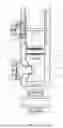
FIG. 1 schematically shows a longitudinal section through a multi-tube vibration damper having adjustable damping force for a vehicle according to one embodiment of the invention,
FIGS. 2a, b, c schematically show a longitudinal section through the damper inner tube comprising the region of the damper tube inner wall opening including a cross section through the damper inner tube in the region of the damper tube inner wall opening according to embodiments of the invention.
FIG. 1 shows a longitudinal section through a multi-tube vibration damper 1 having a damper inner tube 2 that is at least partially filled with damping medium and has a damper inner tube wall, wherein the damper inner tube wall has a damper inner tube inner face DII and a damper inner tube outer face DIA. A piston rod 3 is arranged movably back and forth in the damper inner tube 2, wherein a working piston 4 is movable together with the piston rod 3, by means of which working piston the interior of the damper inner tube 2 is divided into a working chamber 5 on the piston rod side and a working chamber 6 remote from the piston rod. A damper outer tube 7 having a damper outer tube wall is arranged coaxially around the damper inner tube 2, and a compensation chamber 8 is formed between the damper outer tube 7 and the damper inner tube 2. A damping module 9 having a connecting piece 10 is arranged on the outside of the damper outer tube wall, and the connecting piece 10 runs fluid-tightly from the damping module 9 through a damper outer tube wall opening 15 for fluid connection between the working chamber 6 remote from the piston rod and the damping module 9 and opens fluid-tightly into a damper inner tube wall opening 14. A conduit 11 is formed integrally from the damper inner tube wall, wherein the conduit 11 protrudes into the interior of the damper inner tube 2 and opens into the interior of the damper inner tube 2 in the damper inner tube wall opening 14. The connecting piece 10 is arranged coaxially inside the conduit 11. A geometric transition structure 12 is formed as an indentation in the region between the damper inner tube wall and the conduit 11. The connecting piece 10 opening into the damper inner tube wall opening 14 is sealed against the damper inner tube outer face DIA by means of a sealing ring 13 in the mouth region, that is, in the cylindrical region of the damper inner tube wall opening 14.
FIGS. 2a, b, c show longitudinal sections through the damper inner tube 2 having the damper inner tube wall comprising the damper inner tube inner face DII and the damper inner tube outer face DIA, comprising the region of the damper inner tube wall opening 14 including a cross section through the damper inner tube 2 in the region of the damper inner tube wall opening 14, in each case with the conduit 11 and the geometric transition structure 12. The geometric transition structure 12 is shown with a different profile in each of the embodiments of FIGS. 2a, 2b and 2c.
INDUSTRIAL APPLICABILITY
Multi-tube vibration dampers, in particular twin-tube vibration dampers, having adjustable damping force of the type described above are used in the production of multi-tube vibration dampers, in particular of chassis of vehicles, in particular motor vehicles, of motorcycles, of bicycles, of snowmobiles, of electric scooters.
LIST OF REFERENCE SIGNS
-
- 1=Multi-tube vibration damper
- 2=Damper inner tube
- 3=Piston rod
- 4=Working piston
- 5=Working chamber on piston rod side
- 6=Working chamber remote from piston rod
- 7=Damper outer tube
- 8=Compensation chamber
- 9=Damping module
- 10=Connecting piece
- 11=Conduit
- 12=Indentation
- 13=Sealing ring
- 14=Damper inner tube wall opening
- 15=Damper outer tube wall opening
- DII=Damper inner tube inner face
- DIA=Damper inner tube outer face
- L=Longitudinal axis
Claims
1.-6. (canceled)
7. A multi-tube vibration damper for a vehicle having adjustable damping, comprising:
a damper inner tube at least filled partially with a damping medium, and including a damper inner tube wall, wherein the damper inner tube wall includes a damper inner tube inner face (DII) and a damper inner tube outer face (DIA);
a piston rod arranged movably within the damper inner tube;
a working piston arranged movable together with the piston rod, by means of which an interior of the damper inner tube is divided into a working chamber on the piston rod side and a working chamber remote from the piston rod;
a damper outer tube having a damper outer tube wall, wherein the damper outer tube is arranged coaxially around the damper inner tube, and a compensation chamber is defined between the damper outer tube and the damper inner tube;
a damping module having a connecting piece, wherein the damping module is arranged on the outside of the damper outer tube wall, and the connecting piece runs fluid-tightly from the damping module through a damper outer tube wall opening configured for creating a fluid connection between the working chamber remote from the piston rod and the damping module and configured to open fluid-tightly into a damper inner tube wall opening; and
a conduit formed integrally from the damper inner tube wall, wherein the conduit protrudes into the interior of the damper inner tube and opens into the interior of the damper inner tube in the damper inner tube wall opening, wherein the connecting piece is arranged coaxially inside the conduit.
8. The multi-tube vibration damper of claim 1, wherein the damper inner tube wall opening is cylindrical, including a cylindrical edge.
9. The multi-tube vibration damper of claim 1, wherein a geometric transition structure is formed in between the damper inner tube wall and the conduit, the transition structure having a profile differing from an angular profile.
10. The multi-tube vibration damper of claim 1, wherein the geometric transition structure is selected from a group of: an indentation into the interior of the damper inner tube, a bulge into the compensation chamber, a spherical cap shape, a corrugated shape, or a combination thereof.
11. The multi-tube vibration damper of claim 9, wherein the geometric transition structure includes as a stepped profile.
12. The multi-tube vibration damper of claim 1, wherein the, connecting piece opening into the damper inner tube wall opening is sealed against the damper inner tube outer face (DIA) by means of a sealing ring in the mouth region.
Images & Drawings included:


Sources:
- United States Patent and Trademark Office - verify current appl. status at the USPTO↗
Recent applications in this class:
- » 20250172186 2025-05-29
SHOCK ABSORBER AND DAMPING VALVE DEVICE - » 20200124129 2020-04-23
Damper with two-piece shell - » 20190056009 2019-02-21
CYLINDER DEVICE AND METHOD OF PRODUCING THE SAME - » 20180347659 2018-12-06
Combination gas spring and damper - » 20180340588 2018-11-29
SHOCK ABSORBER - » 20180017126 2018-01-18
Damper for a vehicle having a flange for connecting an external module tube - » 20170261061 2017-09-14
SHOCK ABSORBER - » 20170261060 2017-09-14
SHOCK ABSORBER - » 20170254381 2017-09-07
SHOCK ABSORBER - » 20170211650 2017-07-27
CYLINDER APPARATUS
Recent applications for this Assignee:
- » 20250172191 2025-05-29
VIBRATION DAMPER FOR A MOTOR VEHICLE - » 20250172191 2025-05-29
VIBRATION DAMPER FOR A MOTOR VEHICLE - » 20250172189 2025-05-29
VIBRATION DAMPER FOR A MOTOR VEHICLE - » 20250172189 2025-05-29
VIBRATION DAMPER FOR A MOTOR VEHICLE - » 20250172187 2025-05-29
VIBRATION DAMPER FOR A MOTOR VEHICLE - » 20250172187 2025-05-29
VIBRATION DAMPER FOR A MOTOR VEHICLE - » 20250172133 2025-05-29
PISTON-CYLINDER ASSEMBLY FOR A RADIAL PISTON COMPRESSOR, AND RADIAL PISTON COMPRESSOR - » 20250171303 2025-05-29
NITRIC ACID PLANT FOR PRODUCING NITRIC ACID - » 20250171075 2025-05-29
METHOD FOR MEASURING THE RACK FORCE ACTING ON A RACK OF A STEERING MECHANISM OF A STEERING SYSTEM FOR A MOTOR VEHICLE, AND STEERING SYSTEM - » 20250154016 2025-05-15
AMMONIA SYNTHESIS AND UREA SYNTHESIS WITH REDUCED CO2 FOOTPRINT