Helix Electrode For Impressed Current Cathodic Protection
US20240175142A1
2024-05-30
18/058,857
2022-11-25
Smart Summary: A new type of electrode called the Helix Electrode has been created for protecting fluid-containing structures like water tanks from corrosion. Unlike traditional electrodes, this Helix Electrode is made from a lower-cost titanium ribbon stock and has a helix shape that provides more surface area for protection. It can be used inside tanks without short-circuiting against the structure, making it more efficient and cost-effective for impressed current cathodic protection. 🚀 TL;DR
Abstract:
Fluid-containing structures such as water storage tanks often utilize impressed current cathodic protection (ICCP) which generally utilizes custom-cut high-cost oxide-coated titanium electrodes, of which increased surface area typically gives increased protection to the structure. These electrodes must not short-circuit against the structure. This present invention allows the use of a lower-cost commonly-manufactured shape of oxide-coated titanium ribbon stock to fashion a helix-shaped electrode that has increased surface area per linear length unit of electrode when compared to prior art. This present invention can also be embodied such that it is operative with interior-facing electrically conductive surfaces while simultaneously protected on dielectric exterior surfaces from electrical short circuit contact to the electrically conductive surfaces inside the tank, thereby allowing contact or close proximity with said tank-structure electrically conductive surfaces.
Applicant:
Interested in similar patents?
Get notified when new applications in this technology area are published.
Classification:
C23F13/16 » CPC main
Inhibiting corrosion of metals by anodic or cathodic protection cathodic; Selection of conditions, parameters or procedures for cathodic protection, e.g. of electrical conditions; Constructional parts, or assemblies of cathodic-protection apparatus; Electrodes specially adapted for inhibiting corrosion by cathodic protection; Manufacture thereof; Conducting electric current thereto Electrodes characterised by the combination of the structure and the material
Description
PRIOR ART
-
- U.S. Pat. No. 5,176,807, Expandable coil cathodic protection anode, Jan. 5, 1993, Kumar
- U.S. Pat. No. 9,194,047, Anode for cathodic protection, Nov. 24, 2015, Tettamant
- U.S. Pat. No. 10,214,819, Galvanic anode and method of corrosion protection, Feb. 26, 2019, Goodwin
- U.S. Pat. No. 11,091,841, Autonomous impressed current cathodic protection device on metal surfaces with a spiral magnesium anode, Aug. 17, 2021, Kounadinis
BACKGROUND OF THE INVENTION
Other References
-
- NACE STANDARD RP0388-2001
SUMMARY OF THE INVENTION
This present invention is a novel electrode shape that constitutes a helix comprised of an element with a ribbon profile (as seen from a section view of its main element, perpendicular to the element's longest curve) for use with impressed current cathodic protection, typically for application to hot water storage tanks where it provides increased surface area over linear unit length of electrode into the tank when compared to prior art.
BRIEF DESCRIPTION OF DRAWINGS
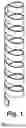
FIG. 1 is an isometric view of an embodiment of this present invention.
FIG. 2 is a top view of an embodiment of this present invention, as seen perpendicular to its long axis.
FIG. 3 is a front view of an embodiment of this present invention.
FIG. 4 is an electrode (produced by Corro-Protec) of existing art, top view, as seen perpendicular to its long axis.
FIG. 5 is an isometric view of a 1-inch sectioned length of an embodiment of this present invention.
FIG. 6 is an isometric view of an unformed 1-inch sectioned length of a titanium MMO base ribbon stock used in an embodiment of present invention.
FIG. 7 is an isometric view of a 1-inch sectioned length of an electrode (produced by Corro-Protec) of existing art.
DETAILED DESCRIPTION OF THE INVENTION
Technical Field
This invention relates to impressed current cathodic protection (ICCP) devices, often termed “powered anodes”, used for controlling corrosion within fluid-containing structures (typically tanks, typically hot water tanks found in residential and commercial use) and in particular to the shape of the electrode used in an ICCP assembly that is in contact with the fluid.
BACKGROUND
Impressed current cathodic protection (ICCP) has been known to the general public for nearly 200 years since the writings of Sir Humphry Davy made available to the Royal Society in London in 1824, and has since been used widely in the protection of corrodible metals, such as those found in ship hulls, steel reinforcement in concrete, steel pipelines, steel oil tanks, water storage tanks, and more. In this process of ICCP, a direct current power source is electrically connected to the electrolyte that is in contact with the structure that is desired to have protection such that a positive current is discharged into the electrolyte, and the structure intended for protection is electrically connected to the negative current of the power source, whereby a level of protection is achieved for those electrically conductive elements that are in a cathodic (negative or ground) state relative to a anodic (positively-charged) electrolyte. The amount of current supplied is ideally decided in large part by the area of exposed electrically conductive material that is in contact with the electrolyte, the composition of that material, and the composition and temperature and fluid-dynamical flow (if any) of the electrolyte. If more of the electrically-conductive material is exposed to the electrolyte then more current is required to retain a minimum current density per unit area. Therefore, with increases of exposed structure area there become increased demands for current. Voltage to drive the necessary current is largely dependent on current demands and resistivity found in the system, of which the major factors are: electrical conductivity of the electrolyte, the distance of structure materials from the discharging anode, the area of the discharging anode, and the composition of the discharging anode. Increased demands for current or voltage generally result in increased demand for electrode area or length or both. If the electrode is located a long distance from the electrolyte-exposed electrically-conductive structure material, then more voltage is required to drive the current through that distance to achieve the intended protection. If the distance between the structure and electrode are reduced, then the electrical resistance is reduced and the anode area can be reduced or voltage or current delivered by the power source can be reduced while still maintaining the intended protection. Therefore, an electrode with greater surface area, a longer electrode or an electrode that is extended to be located more closely to the corrodible electrolyte-exposed electrically conductive structure (or all the above, or a combination of the above) can often be beneficial, either in terms of system materials costs, or power costs, or protection delivered, or all or a combination of these.
Due to these above-mentioned effects and constraints upon electrode area and length, different lengths or different areas or different shapes of electrodes will bring with each different negative and positive effects on the system, as well as differing costs of production, thus giving impetus to this present invention.
DESCRIPTION OF RELATED ART
Existing and prior art of the electrodes found in the use of ICCP of structures in contact with an electrolyte are found to be of the following types or shapes, generally made from titanium that is coated with mixed metal oxides, or in rare cases, of platinum with no coating:
Ribbon, Flat
A cross section perpendicular to the long axis of this type will find it to be of some sort of rectangular shape, having a width typically many times its height. Two common sizes of this ribbon are 0.25-inches*0.025-inches and 0.5-inches*0.035-inches. This ribbon is typically utilized in its flat condition, without additional shaping. This type of electrode is not typically used for interfacing with electrolyte, and is often used to interface with wet soils in the protection of steel-reinforced concrete structures as well as large metal structures such as oil pipe lines and oil tanks that are in direct contact with soil.
Ribbon, Bent
ICCP assemblies produced by a Canadian company called Corro-Protec utilize essentially a rectangular ribbon that has been bent at the center along its long axis at approximately a 120-degree included angle, as can be seen in top view, FIG. 4, or in isometric view of a 1-inch length section view, FIG. 7. It is observed that this bend could (if the base ribbon were larger) allow a larger surface area of electrode to be inserted through an opening into a tank than what could be achieved without the bend, and even more surface area (increased total width of unformed base stock of the electrode) could be inserted if the angle of the bend were increased. This bend provides a certain amount of rigidity to the electrode, likely so that it is not accidentally misshapen after manufacturing or during installation.
Ribbon, Twisted
ICCP assemblies produced by the inventor of this present invention are currently being sold under the U.S. business entity “STOLTCO, LLC” that utilize a ribbon that is twisted by fixturing both small ends of the ribbon and turning in opposite directions until a point somewhat below yield and buckling of the ribbon and its material. This twist provides a certain amount of rigidity to the electrode so that it is not accidentally misshapen after manufacturing and until and during installation.
Plate
Electrodes in plate form are readily available, and are often simple rectangular shapes of various sizes and thicknesses, and are often bolted together with dielectric standoffs to form an anode electrode assembly. It is noted that these interface with electrolytes, but are not typically used for ICCP.
Rod Or Wire, Straight
Electrodes in rod or wire form, namely that of a cylinder, are often used to protect tanks of water. A U.S.-based company, A.O. Smith sells an ICCP assembly that utilizes a straight rod made from titanium and coated with metal oxides as an electrode.
Tube
A seller entity named “briidea” found on the U.S. www.amazon.com website sells an ICCP assembly that utilizes a tube as the electrode. A seller entity named “DROMIX” found on the U.S. www.amazon.com website sells an ICCP assembly that utilizes either a perforated tube or expanded mesh tube as the electrode.
Rod or Wire, Coiled:
U.S. Pat. No. 5,176,807 describes an ICCP assembly that utilizes an expanding or extendable coil, much like an easily-yielding spring, which is stretched prior to installation into a tank so as to provide a long electrode length within the tank, thereby decreasing distance to any exposed structure, and in general decreasing the resistance of the system. For a period of time, now ended as of the time of this writing, a seller on the U.S. www.amazon.com website was selling such-described coil-electrode ICCP device under the name “CerAnode”. The intent and claims of U.S. Pat. No. 5,176,807 are based on an expandable or extendable coil. The helical electrode described in this present invention is not intended to be expanded or extended in normal use, nor does its composition from ribbon stock lend itself to this feature. The description and claims of U.S. Pat. No. 5,176,807 thoroughly describe the use of a reasonably malleable (extendable) wire and not a ribbon as in this present invention. The drawings in U.S. Pat. No. 5,176,807 show a cylindrically-shaped wire, and there is no reason to believe that another shape is claimed in this patent. There is no mention of cross-sections or ratios or other geometry or dimensional aspects of the wire, and the focus is upon its ability to extend or expand. In this present invention, there is no focus on extension or expansion of the electrode, and there is explicit reference to its geometry, and of its geometry lending to its utility of increasing surface area, and the novel use it finds in the helix shape in this application. U.S. Pat. No. 5,176,807 describes use of “a stabilizing element secured to the lower end of said lower segment to prevent electrical contact between said lower segment and the adjacent surface of the chamber”, where this present invention makes no claim for this element due to a lack of extension of this present invention. This “stabilizing element” in U.S. Pat. No. 5,176,807 is claimed also to be of “a weight which is sufficient to maintain said helical coil in an extended position”, a weight which is unnecessary in this present rigid helix electrode, and a weight of which has the possibility when used with an easily extendible wire electrode such as in U.S. Pat. No. 5,176,807 to slide to the exterior perimeter of the cylinder tank wall at the bottom of a heated tank which is typically convex when seen from the inside of the tank on gas-heated tanks; whereby at this position the conductive wire electrode is at risk of short-circuiting to conductive elements within the tank such as drain valves or thermostats, or to the tank wall itself. This present invention avoids this risk because it is not easily extendable and typically of a much shorter length and typically not utilizing a weight for the purpose of extending the electrode.
U.S. Pat. No. 9,194,047 claims a composite strip consisting of one side that presents as dielectric and other side presenting electrically conductive, although it lists also several other features and intrinsic to the invention is its composition being that of titanium, and the dielectric punctured by a multiplicity of holes or openings. U.S. Pat. No. 9,194,047 is quite different from this present invention, wherein this present invention includes an embodiment that utilizes similarly a strip or ribbon that is electrically conductive one side, dielectric on opposing side, but is dependant on its shape as a helix, which bestows upon it the benefit not claimed by U.S. Pat. No. 9,194,047 of the ability to contact electrically conductive surfaces with its outwardly-oriented dielectric surface without causing electric short circuit.
U.S. Pat. No. 10,214,819 claims “A galvanic anode comprising: an anode body comprising at least one helical coil comprising a sacrificial metal and a longitudinal axis”, which generally seeks the same benefits this present invention seeks, and also utilizes the helix to achieve these benefits, that of an easily fabricated, low-cost device for cathodic protection that provides a maximum of protection by a minimum amount of (linear unit distance, in this present invention) (volume, in U.S. Pat. No. 10,214,819); it should be noted, however, that U.S. Pat. No. 10,214,819 is explicitly that of a sacrificial anode, whereas this present invention is the electrode which is used explicitly in an impressed current cathodic protection system (ICCP), which can offer greater corrosion control and over a longer period of time, a clear benefit in some applications relative to U.S. Pat. No. 10,214,819.
U.S. Pat. No. 11,091,841 claims “An autonomous impressed cathodic protection device, comprising a central magnesium anode core”, and while it too takes some advantage and novelty from the helix shape, the spiral shape is laid upon a flat plane and not of linear progression about a central axis as this present invention, and is of sacrificial nature whereby its (mostly magnesium) materials degrade and “sacrifice” themselves in order to provide the cathodic protection to the structure; this is in contrast to this present invention, which relies upon electrical current from an outside source and which is the electrode of an ICCP system and of which the helix is quite different than the largely 2D-oriented spiral of U.S. Pat. No. 11,091,841; this present invention can provide better corrosion protection than U.S. Pat. No. 11,091,841 due to utilizing voltage and current from an outside source which can be controlled and of much higher values, as well as being of non-sacrificial materials which can last many times longer than the sacrificial materials used in U.S. Pat. No. 11,091,841.
Summary of Argument of Novelty of this Present Invention
Impressed Current cathodic protection relies on electrodes to disperse electrical current into an electrolyte.
-
- Electrodes may have advantages when the following aspects are included in its construction or in its inclusion into an ICCP assembly/device:
- Low cost.
- Maximizing depth into tank when installed, and/or proximity to exposed corrodible electrically-conductive surfaces that are in contact with the electrolyte.
- Maximized electrode area.
- Small shipping size.
- Ability to withstand typical handling/installation without substantial deformation or harm to any oxide coatings.
- Electrodes may have advantages when the following aspects are included in its construction or in its inclusion into an ICCP assembly/device:
The problems with prior art rod or wire (straight or coiled) electrodes are:
-
- Lack of surface area per linear unit of length.
- Long length to achieve satisfactory area, but which increases shipping costs.
The problems with flat electrodes are:
-
- Lack of geometric strength (it is easily bent).
- Lack of surface area per linear unit of length, due to constrained width as a requirement of installation through a hole in a tank.
The problem with electrodes with a bend or bends along their long axis are:
-
- Lack of surface area per linear unit of length, due to constrained width as a requirement of installation through a hole in a tank.
- Large or powerful (or both) forming tools required to form.
The proposed invention of a ribbon shaped into a helix has these benefits over prior and existing art:
-
- This present invention of a helix electrode can use a ribbon base stock material that is common to ICCP industry, has many manufacturers, and is among the lowest cost of manufactured electrode base materials available.
- This present invention of a helix electrode has a greater useful surface area per linear length unit than prior art which can fit through similar-sized tank entry holes.
- This present invention of a helix electrode has good geometric strength during normal shipping, installation, and use activity.
- This present invention of a helix electrode gives efficient use of inside surfaces to disperse used electrical charge, when compared to prior art tube electrodes.
- This present invention of a helix electrode can be manufactured with an outside-facing dielectric surface which allows for contact with conductive elements of the structure without electrical short circuit, something which prior art does not offer.
Definitions
In the scope of the writings describing this invention, and to aid in understanding of the field and the invention, the inventor wishes to use the following definitions and acronyms:
ICCP: (Impressed Current Cathodic Protection). A method of corrosion protection whereby an electrical current is used to control the corrosion of electrically-conductive corrodible materials by the method of impressing an electrical current upon an electrolyte that is in contact with said materials, the electrolyte accepting a (DC) positive charge from the current source, and the structure of which the control of corrosion is sought made to function as the (DC) negative or ground in the electrical circuit.
Electrode: an electrically conductive element used to discharge an electrical current, typically into another medium such as an electrolyte.
Ribbon: a long, narrow strip. An element that has a length that is much longer than its width and height, and also has a width that is substantially larger than its height.
Electrolyte: A medium, typically a fluid, that can conduct electrical charge. In the scope of this invention, water is considered an electrolyte.
MMO (Mixed Metal Oxide): Oxides of more than one metal; typically oxides of iridium and tantalum, but not limited to these.
Powered Anode: Typically an assembly which is fastened to a structure for the purpose of accepting an electrical current from an outside source and delivering the positive side current of the electrical circuit to an electrolyte. Sometimes this assembly may also deliver the negative electrical current to the structure. The assembly, in the scope of this invention, typically consists of an electrode that is in contact with an electrolyte, a rigid fitting—often threaded—for fastening to a structure, and internal dielectric sealing materials which prevent short circuit and also often seal the tank environment and associated electrolyte/atmosphere/pressures from the environment outside the tank.
DETAILED DESCRIPTION OF THE INVENTION
This present invention is that of an electrode for use in ICCP comprised of a helix (isometric view, FIG. 1), that, a section view of its main element perpendicular to the element's longest curve would show a profile of a ribbon, this main and sole element being comprised in part or in whole or in combination of an electrically conductive material, typically a metal base stock, preferably titanium, and is on its surfaces that are intended for electrical conductivity preferably coated with a metal oxide or mixed metal oxides which increase its useful life. The helix generally consists of greater than one complete revolution of its primary element about a central axis, and typically consists of greater than two revolutions, there being no limit to the number of revolutions except in that which is practical from manufacturing, shipping, installation, and use limitations or negative consequences. The ribbon material can be composed of various types of electrically-conductive materials which can offer varying degrees of resistance to hydrolysis, such as electrically-conductive polymer, metals, electrically-conductive ceramics, or other electrically conductive materials suitable for use in ICCP of fluid-containing structures. The invention can be made to various lengths or diameters according to the demands of the environment it is expected to operate in and according to the lifetime use desired. The helix overall, its silhouette as seen from a front view (such as embodiment example FIG. 3) is typically cylindrical or conical in shape, as seen by its outside perimeter contour, or as seen at its inside diameter indicated at 1 in FIG. 2. A conical or tapered shape, as seen in a silhouette front view, slight or obvious, may increase the ability of the formed helix to be released from a forming tool, the helix being removed in the direction of the small end of the taper. Reduction of the diameter of a portion of the helix at either or both ends (often in an operation after forming the general helix shape) may provide ability for the finished helix to be more easily inserted or removed through a hole, due to a gradual reduction of diameter creating an inclined plane which can act as a ramp to guide the helix through a hole. Bending one or both ends out of the helix shape for use as electrical connection to additional components in an ICCP system is seen as desirable and not impacting the benefits derived from a generally helix-shaped electrode. Typically there will be space 2, FIG. 3, between the revolutions of material of the helix, as well as throughout the interior of the helix shape, which allows there the presence of electrolyte during use, and thus also the transfer of electrical charge through said electrolyte that exists between the elements of the helix, which typically originates from the interior of the helix. This space 2, FIG. 3, may be of differing dimension, according to a variety of factors, such as electrolyte type, manufacturing tolerances, electrode surface area needed per linear unit length, electrode material type and resulting lifetime of use, and more.
In general the invention will be produced with one side of the ribbon generally facing inward toward the central axis of the helix such that the opposing side of the ribbon will generally face outward from the central axis of the helix (generally the ribbon will not twist relative to the central axis of the helix, but will revolve around it, with the broad side of the ribbon that facing inwards remaining so throughout the duration of revolutions of which the helix is composed, the exceptions typically only being the manipulation of the ends of the ribbon, not exceeding ¼ of the total length of the ribbon). In typical embodiments, the ribbon, in its straight un-formed base condition, will typically be of a common material composition and characteristic from side to side as assessed from both a front and side plane created through its theoretical long central axis. However, this present invention may benefit from being manufactured from a base stock ribbon that is conductive on one broad face, or conductive on one broad face as well as two or partially two of its narrow sides, while the remaining broad face or broad face as well as two or partially two narrow sides are of a dielectric material or possess a dielectric coating; the formed invention (helix electrode) then is produced with the dielectric broad face facing away from the central axis of the helix. This embodiment with outward-facing dielectric surfaces can allow the helix electrode to directly contact electrically conductive elements within the structure without causing electrical short circuit—said electrical short circuit would rob the electrolyte of electrical charge, and thus rob other electrically-conductive elements of the structure in contact with the electrolyte of said charge, thereby reducing corrosion protection of those elements. Therefore, in certain equipment or structures which bear increased risk of contact to interior-located electrically conductive elements, this present invention, and specifically the embodiment that utilizes one or more outward-facing dielectric surface faces, can provide increased corrosion protection at potentially lower cost over prior and existing art.
In general, this present invention possesses the following benefits that set it apart from prior art:
It easily utilizes commonly-manufactured electrode material, such as MMO ribbon that is typically manufactured and sold for use in the protection of steel in concrete structures, and thereby saves on cost due to avoiding custom-cut sheet stock into custom size flat shapes. Also due to common availability of base stock, suppliers may be changed easily, speedily, and with low-risk if circumstances force it, or to gain lower pricing.
Low-cost of forming operation, due to requiring only a simple cylindrical mandrel to form, with no special perforations or large bending brake presses required.
Increased active area per linear unit of electrode in comparison to ribbon formed in twist or bent or straight—that can fit through a finite sized hold in a structure, such as that of a ¾-inch NPT fitting. Referencing FIG. 7, which is an isometric view of a 1-inch sectioned length of an electrode (produced by Corro-Protec) of existing art, this section, including all surfaces except those section cuts on both ends that are perpendicular to the long axis of the electrode drawing, has a surface area of 1.16-square-inches, as measured by 3D CAD. Comparatively, a similar section view of an embodiment of this present invention gives (FIG. 5) a surface area of 2.21-square-inches, while utilizing a low-cost commonly available base stock. Comparing this section embodiment of this present invention (FIG. 5) to similarly sectioned 1-inch length of the base ribbon stock used to produce it, we can arrive at 0.55-square-inches of area for the unformed base stock section, giving a “surface area over linear unit length” advantage to this present invention—an advantage which can lower shipping costs or potentially increase corrosion protection to the structure during use, or both.
Increased effectiveness of area per linear length unit of electrode relative to total surface, in comparison to solid tubes. This is because the inside of a tube is largely not active due to the limited current-carrying capacity of each cubic unit of electrolyte, ie, a large amount of current from the inside surface of the tube can only affect the electrolyte between the tube and the structure by exiting one end of a small tube, and the exit area of the tube is not large enough to allow most electrolytes, especially water, to carry out through the exit hole most of the current imparted from the inside of the tube due to the innate typically high resistance low-current carrying capacity of the electrolyte, whereby only a small fraction of the current available to the electrolyte on the inside of the tube is actually transferred through the exit hole of the tube. Therefore it is primarily the exterior of a solid tube that is useful in providing electrical charge to the electrolyte; in contrast, the helical electrode has gaps between revolutions which allow current to travel from inside surfaces through the electrolyte that fills the gaps between revolutions and out to structure surfaces. Mainly, the helical electrode offers a much greater amount of electrode surface area that has large electrically conductive pathways through electrolyte when compared to a solid-walled tube. In contrast to a perforated or expanded mesh tube, the helix electrode typically attains a higher amount of surface area in each linear unit of electrode, and at a much lower manufacturing cost due to the use of standardized common ribbon material.
Increased active area per linear unit of electrode in comparison to straight or coiled rod or wire. It is not cost effective to produce a solid rod or wire that can match the surface area of a straight ribbon anode due to the solid core which amounts to greatly increased mass of material used; especially it is not cost effective per linear unit of electrode to produce a straight or coiled rod or wire compared to a helix-shaped ribbon anode, again due to the material required. Unlike the wire-electrode listed in U.S. Pat. No. 5,176,807, this present invention's use of ribbon can greatly increase the electrode surface area per linear length unit of installed electrode while using a minimum amount of material by weight.
Reduced shipping costs, due to ribbon being shipped flat from a material supplier to a forming operation whereupon it is formed and assembled; in contrast to tubes which take up a much greater volume of space.
Can be fashioned from an electrically-composite material, whereby the helix shape is of dielectric exterior surfaces, and electrically-conductive interior surfaces which allows for contact with electrically-conductive surfaces without short-circuiting to them.
In general, the core recognizable attributes of this present invention are that it is a helix generally with space between elements, fashioned from an wholly or selectively electrically conductive ribbon-shaped material and intended for use in ICCP systems for direct interaction with the electrolyte as the discharging electrode of the system.
Embodiments
There are many possible variations of embodiments of the helix electrode, of the most obvious, such categories may be:
Creating the helix of different inside diameters. In some cases, a smaller size may give cost savings in shipping. In other cases, as large of a size as can fit through any opening in installed structures may offer the most area per linear unit length of electrode.
Creating the helix in different lengths. Different lengths will offer different surface areas with commensurate costs.
Creating a tapered helix. A tapered helix may be beneficial during manufacturing, such that a mandrel is used with a larger taper at top than bottom for easy removal of the formed part off the bottom of the mandrel.
Creating a helix with different sized or shaped base material profile. As titanium processing technology and MMO electrode technology moves forward, a more cost-effective electrode shape may present itself which may prove advantageous to use, although it is highly likely to be of similar rectangular ribbon profile.
Creating a helix of different or varying pitches. Varying the pitch of the spacing that the helix is comprised of may lend itself to greater surface areas in particular linear locations over others, which may be advantageous in particular installations. Aesthetic appeal may also be increased by tightening the pitch at one or both ends of the electrode. Tightening the pitch at an end of the electrode of which a small portion is subsequently bent out of the shape of a helix for the purpose of central fastening to another electrically conductive element may also be attractive, as discussed later in this writing.
Creating a helix from an electrically-composite material, whereby the helix shape is of dielectric exterior surfaces, and electrically-conductive interior surfaces. In this material composition embodiment, the helix may first be formed, and then coated with a dielectric material such as a vitreous coating or a polymer powder-coating. It may also be fashioned wholly from a polymer co-extrusion made of one polymer composition that is dielectric, the other polymer electrically conductive (both of which are readily available on the market at the time of this writing), and the two polymers each isolated largely to each opposing broad sides of the ribbon; forming being typically performed in a typically thermally softened state similar to “drape forming” by rotating it about a mandrel or form and allowing it to cool in its final helix shape with the dielectric side of the ribbon facing outward from the central axis of the helix.
A Preferred Embodiment
What the inventor deems a preferable and most easily understood embodiment for the purpose of delivering electrical current to an electrolyte inside a tank that is accessed through a ¾-inch NPT female fitting, is a formed helix, as shown in FIGS. 1, 2, and 3, and comprised of the following specifications, followed by a short description of the forming process, assembly into ICCP assembly, installation, and use in operation.
Created from a base stock (unformed) with a profile of approximately 0.25-inches*0.025-inches, and a length of approximately 16.9-inches, being of a commonly obtained mixed-metal-oxide coated titanium electrode material, the oxides being typically primarily of Iridium and Tantalum. This base stock is readily available and of low cost, easily formable, allows for a long life of use in water or wet environments, and is easily shipped.
As-formed electrode: a helix FIG. 1, with an inside diameter 1, shown in FIG. 2, of approximately 0.59-inches, and an outside diameter no larger than 0.86-inches. The limitation of 0.86-inches in this embodiment is to allow comfortable installation through ¾-inch NPT female fitting holes commonly found on hot water storage tanks, although many different diameters are acceptable for use.
As-formed electrode: helix length of 4-inches up to any length necessary to provide the protection needed for the expected lifetime of the product, which approximately 4-inches to 6-inches preferred, though many lengths are acceptable for use.
As-formed electrode: Pitch or separation of linear like-elements of the helix typically of 0.5-inches, or with a minimum gap 2, such as shown in FIG. 3, typically of 0.12-inches. The gap is to allow electrolyte to be present between areas of the electrode material so as to provide pathways for electrical charge through said electrolyte to transfer from electrode surfaces found on the inside of the helix to exposed electrically conductive areas of the structure that are typically found some distance away from the electrode. Many different gaps of separation between elements of the helix are acceptable for use, including no gap, with each gap distance comes varying costs and benefits, both in terms of production and in terms of performance. The formed helix electrode will generally be comprised of one or more revolutions of its primary element.
A Mode for Carrying Out the Above-Described Invention
Typically the base ribbon stock is measured and cut to a specified length, preferably with automated equipment.
The cut ribbon stock is mounted at an angle at one end into a slot of a mandrel or largely cylindrical forming tool which thereby typically defines the pitch of the helix. The mandrel or forming tool is typically attached to motorized or rotatable equipment and rotated until the helix is completed, typically during a specified length of time or during a specified number of turns during which the ribbon is either (A) kept in tension from its loose end, or (B) a fixed tool or roller presses the ribbon to the mandrel as it spins, keeping tension and/or proximity close enough to the mandrel so as to cause permanent yielding and forming of the ribbon material to the mandrel. The end result is that the ribbon is formed into a helix, typically with a repeatable amount of springback.
After forming the majority of the body of the helix, it may be preferable—if not already accomplished by the fastening feature in the mandrel—to slightly bend one end of the the ribbon that comprises the helix toward—or coincident to—the central axis of the helix so as to provide a central point of fastening to the helix to another element during further assembly into a “powered anode” assembly. This bend of a small amount of material to axial location is not required, though it is seen as preferred from an aesthetic standpoint, as well as from the standpoint of the installer who may insert the assembly through a hole during installation and likewise may at some point remove it, whereby it is seen as desired that the finished assembly which utilizes the helical electrode will have a high degree of symmetry about its axis.
A Use in ICCP Assembly
The helix electrode will typically be fastened, preferably by welding, preferably spot welding, to an electrically-conductive element, typically of titanium, which is to pierce through any sealing materials that are within a typically metal fitting, and provide an electrical path to connectors or wires that lead to a DC power source, or a portion of the helix may offer direct connection itself. Therefore, the helix electrode will typically be the primary element that discharges an electrical current into the electrolyte though direct contact with said electrolyte. The helix electrode may sometimes be fixtured to a rod, ribbon, wire, twisted wire cable, or other electrically conductive element that interfaces with the sealing materials inside a typically metal fitting that is intended for fastening to a structure. These other electrically conductive elements may sometimes be used to offset the length of the helix electrode to be specific distances away from the fitting to which it is attached, typically for the purpose of decreasing the distance of the electrode to areas of the structure that are most distant. The completed assembly can typically be installed or replaced independent of a power supply that it is typically used with, although it is also possible to permanently attach the wires of the power supply to the ICCP assembly which includes this present invention of the helix electrode. This present invention may be used in assemblies that are fastened to structures by means other than threaded fittings, and its benefits and novelty remain; examples might be a fitting which relies on a flange that is fastened by bolts, clamps, toggles, or levers. In structures that do not require sealing from the environment, this invention may simply be hung into the electrolyte by one of the electrically conductive elements that supply it power from the outside source, or it may be secured in a dielectric material such as a tapered plug, or an plug made of an elastomeric material, which is then fastened to the tank via friction-fit (interference fit) in an opening in the structure. Mainly, the helix electrode's use in an ICCP assembly is that of the discharging electrode, and therefore it will possess an electrically conductive path through any fixturing elements it is a part of, to the output of an external power supply source. This electrically conductive path will most typically be made of materials similar to that of the electrode, such as a mixed metal oxide coated titanium or sole titanium, or a conductive polymer, but it can be made from a great variety of electrically conductive materials that can withstand the environment within the tank as well as shipping and installation activities (such materials can include metals, graphite, conductive polymers, conductive ceramics, glass-metal ceramic compositions, and others).
Use During Installation
The assembly, including its helix electrode element, will typically be inserted through a threaded fitting opening to the tank, with the helix electrode first being inserted, and the assembly fastened through the use of threads on the fitting portion of the assembly. It will then be connected to a DC power source, typically through a connection at the top of the assembly such as a flag or spade terminal, or a bolt and eyelet, or a barrel connector, or any number of cost-effective electrical connections available which provide an electrical path to the helix electrode.
A Use During Operation
Upon connection to a DC power source, the electrically conductive portions of the helix electrode, when in contact with an electrolyte that is in contact with the DC negative portions of the same circuit, will begin discharging a positive DC current flow into said electrolyte, whereby the normal mechanism of ICCP occurs and a level of corrosion protection is attained. In the use of a helix electrode that was fashioned such that the outside surfaces are substantively dielectric, and the inside surfaces electrically conductive, then it functions to transfer electric charge to the electrolyte through its electrically conductive surfaces while preventing short circuit through its dielectric surfaces. If a fitting is a part of the assembly, then the elements of the seals and threads of the fitting—both of which are not claimed nor required in any way in this invention—should provide any necessary sealing of the electrolyte and atmosphere and pressures within the tank from the environment outside the tank. The job of the helix electrode is to effectively and efficiently—in both scientific and cost terms—discharge electrical current into the electrolyte. The amount of current and necessary voltage to drive said current to provide the desired amount of corrosion protection of the structure depends on many variables, including the amount of protection desired; generally the power supplied with be of a constant current due to the assumption of a given amount of conductive surface within the tank the system is applied to, and also under the assumption of the electrolyte within the tank. In the case of hot water storage tanks found in residential use in the United States, generally the outside power source will provide between 2 and 36 volts to drive the current, and generally the current will amount to a MINIMUM of 0.5 mA per 1-foot{circumflex over ( )}(0.0035 mA/in{circumflex over ( )}) of electrically conductive corrodible surfaces in contact with the electrolyte, in general accordance with NACE STANDARD RP0388-2001, and so different values of electrical current may be desired for differing tank structures.
DISCOVERY AND LIKE NAMES
For the purpose of aiding discovery of this invention, the inventor wishes to note that in common speech the invention may sometimes be described under the following terms: Helical electrode, Helically-shaped electrode, Helix powered anode, Spiral electrode, STOLTCO helical powered anode, STOLTCO helix powered anode, Screw shaped powered anode rod
Claims
What is claimed is:1. A helix-shaped electrode, of which a section view of its main element perpendicular to the element's longest curve shows a profile of a ribbon, utilized to deliver an electric current to an electrolyte for the purpose of controlling corrosion of structures that are in contact with the electrolyte.
2. A helix-shaped electrode, comprised as measured by weight 10% or greater of titanium, utilized to deliver an electric current to an electrolyte for the purpose of controlling corrosion of structures that are in contact with the electrolyte.
3. A helix-shaped electrode mounted to a threaded fitting either directly or through various intermediaries or intermediary material, said fitting which is sealed for water-tightness for use in water storage tanks for the purpose of delivering an electric current to the fluid in the tank for the purpose of controlling corrosion of the tank or for controlling corrosion of any electrically conductive attached elements that are in contact with the fluid or both.
4. The helix-shaped electrode, according to claim 1, in which the number of full 360-degree revolutions that make up the geometry of the helix is greater than 1.
5. The helix-shaped electrode, according to claim 2, in which the number of full 360-degree revolutions that make up the geometry of the helix is greater than 1.
6. The invention, according to claim 2, of which a section view of its main element perpendicular to the element's longest curve shows a ratio of greater than 3:1 of the width-to-length ratio of its shape, largely being that of a rectangle.
7. The helix-shaped electrode, according to claim 3, in which the number of full 360-degree revolutions that make up the geometry of the helix is greater than 1.
8. The helix-shaped electrode, according to claim 3, of which a section view of its main element perpendicular to the element's longest curve shows a ratio of greater than 3:1 of the width-to-length ratio of its shape, largely being that of a rectangle.
9. The helix-shaped electrode, according to claim 3, in which the ribbon is of dimensions that do not readily allow for useful expansion or extension of the invention and that the invention typically remains in its manufactured shape during and after installation.
10. The helix-shaped electrode, according to claim 3, in which the ribbon is comprised 30% or more by weight of titanium, or an electrically conductive polymer, or an electrically conductive ceramic, or an electrically conductive metal oxide, or all or a combination of the aforementioned substances.
Images & Drawings included:


Sources:
- United States Patent and Trademark Office - verify current appl. status at the USPTO↗
Recent applications in this class:
- » 20250171908 2025-05-29
Sealed Glass Ceramic Powered Anode Assemblage and Method For Impressed Current Cathodic Protection - » 20240117499 2024-04-11
CORROSION RESISTANT BIMETAL - » 20240093381 2024-03-21
METHOD AND APPARATUS FOR CATHODIC PROTECTION OF STEEL IN A CONCRETE STRUCTURE LOCATED IN AN IONICALLY CONDUCTIVE LIQUID - » 20240052500 2024-02-15
Cathodic protection of metal substrates - » 20230060648 2023-03-02
Corrosion resistant bimetal - » 20220136114 2022-05-05
Self-cleaning anode for cathodic protection systems, cathodic protection systems including the same, and methods of use - » 20210189570 2021-06-24
OLEOPHOBIC AND HYDROPHILIC CONDUCTIVE COATING FOR IMPRESSED CURRENT CATHODIC PROTECTION ANODE - » 20200308712 2020-10-01
Cathodic corrosion protection with current limiter - » 20200216966 2020-07-09
Cathodic protection of metal substrates - » 20200123666 2020-04-23
NEST WITH PRIMARY ANODE