PORTABLE POWER BANK
US20240266853A1
2024-08-08
18/228,953
2023-08-01
Smart Summary: A portable power bank can connect to a mobile device with a screen. It has a battery inside that charges the device and a display on the front side. The power bank also has a special module that receives signals from the mobile device. This allows the display to show a mirror image of what is on the mobile device's screen. It works with different brands of mobile devices, providing both charging and screen mirroring features. 🚀 TL;DR
Abstract:
A portable power bank, which is to be coupled with a mobile device having a screen, includes a housing, a battery, a display, and a signal receiving module. The housing has a front side and a back side to be coupled with the mobile device. The battery is disposed inside the housing for charging the mobile device. The display is disposed at the front side of the housing. The signal receiving module is electrically connected with the display. The signal receiving module wirelessly receives a signal transmitted by the mobile device to enable the display to show a mirror image of an image of the screen of the mobile device. In this way, the portable power bank can show the mirror image of the screen image of mobile devices of different brands and charge the mobile devices.
Applicant:
Interested in similar patents?
Get notified when new applications in this technology area are published.
Classification:
H02J7/0044 » CPC main
Circuit arrangements for charging or depolarising batteries or for supplying loads from batteries characterised by the mechanical construction specially adapted for holding portable devices containing batteries
H01M10/425 » CPC further
Secondary cells; Manufacture thereof; Methods or arrangements for servicing or maintenance of secondary cells or secondary half-cells Structural combination with electronic components, e.g. electronic circuits integrated to the outside of the casing
F16M13/005 » CPC further
Other supports for positioning apparatus or articles ; Means for steadying hand-held apparatus or articles integral with the apparatus or articles to be supported
G06F3/1454 » CPC further
Input arrangements for transferring data to be processed into a form capable of being handled by the computer; Output arrangements for transferring data from processing unit to output unit, e.g. interface arrangements; Digital output to display device ; Cooperation and interconnection of the display device with other functional units involving copying of the display data of a local workstation or window to a remote workstation or window so that an actual copy of the data is displayed simultaneously on two or more displays, e.g. teledisplay
H01M2010/4278 » CPC further
Secondary cells; Manufacture thereof; Methods or arrangements for servicing or maintenance of secondary cells or secondary half-cells; Structural combination with electronic components, e.g. electronic circuits integrated to the outside of the casing Systems for data transfer from batteries, e.g. transfer of battery parameters to a controller, data transferred between battery controller and main controller
H02J7/00 IPC
Circuit arrangements for charging or depolarising batteries or for supplying loads from batteries
H01M10/42 IPC
Secondary cells; Manufacture thereof Methods or arrangements for servicing or maintenance of secondary cells or secondary half-cells
H01M50/247 » CPC further
Constructional details or processes of manufacture of the non-active parts of electrochemical cells other than fuel cells, e.g. hybrid cells; Mountings; Secondary casings or frames; Racks, modules or packs; Suspension devices; Shock absorbers; Transport or carrying devices; Holders specially adapted for portable devices, e.g. mobile phones, computers, hand tools or pacemakers
H01M50/262 » CPC further
Constructional details or processes of manufacture of the non-active parts of electrochemical cells other than fuel cells, e.g. hybrid cells; Mountings; Secondary casings or frames; Racks, modules or packs; Suspension devices; Shock absorbers; Transport or carrying devices; Holders with fastening means, e.g. locks
H02J50/10 » CPC further
Circuit arrangements or systems for wireless supply or distribution of electric power using inductive coupling
H04M1/72412 » CPC further
Substation equipment, e.g. for use by subscribers; Mobile telephones; Cordless telephones, i.e. devices for establishing wireless links to base stations without route selection; User interfaces specially adapted for cordless or mobile telephones with means for local support of applications that increase the functionality by interfacing with external accessories using two-way short-range wireless interfaces
Description
BACKGROUND OF THE INVENTION
1. Field of the Invention
The present invention relates generally to mobile devices, especially a portable power bank with mirror display function.
2. Description of the Related Art
Mobile devices, such as mobile phones and tablet computers, are generally equipped with rear lens, and most mobile devices are equipped with front lens to facilitate users to take selfies. However, due to cost or manufacturing technology considerations, the shooting quality and focal length range of the front lens of most mobile devices are not as good as the rear lens. Therefore, many users who pursue image quality will take selfies with the rear lens. However, the images captured by the rear lens are displayed on the screen opposite to the rear lens, so users cannot accurately catch the viewing range of the lens, resulting in inconvenience in use.
In order to allow users to catch the viewing range more accurately, there is currently a solution of attaching a small mirror to the back of the mobile device. Although this way may improve the above-mentioned defect, it can only roughly catch the viewing range. Another solution is to fix a smart watch on the back of the mobile device. By means of using the display screen of the watch to display synchronously with the mobile device, the viewing image of the rear lens can be displayed on the watch. Although this way can accurately display the viewing range, the users need to purchase a smart watch, which is not only expensive, but also may encounter a problem that smart watches of different brands cannot be paired with mobile devices of specific brands. As such, this solution is still inconvenient to use.
In another aspect, the functions of mobile devices of nowadays are becoming more and more powerful, and users frequently use various functions of the mobile device to make the battery life insufficient. Especially, when taking pictures or recording videos, if the power is insufficient, it will be difficult to capture fleeting brilliant moments.
SUMMARY OF THE INVENTION
The present invention has been accomplished in view of the above-noted circumstances. It is an objective of the present invention to provide a portable power bank, which can display mirror image of the screen image of the mobile devices of different brands, and can charge the mobile devices.
To attain the above objective, the present invention provides a portable power bank, which is adapted to be coupled with a mobile device having a screen, and comprises a housing, a battery, a display, and a signal receiving module. The housing has a front side and a back side. The back side is adapted to be coupled with the mobile device. The battery is disposed inside the housing for charging the mobile device. The display is disposed at the front side of the housing. The signal receiving module is electrically connected with the display. The signal receiving module is configured to wirelessly receive a signal transmitted by the mobile device to enable the display to show a mirror image of an image of the screen of the mobile device. In this way, the portable power bank can show the mirror image of the screen image of mobile devices of different brands, and charge the mobile devices.
BRIEF DESCRIPTION OF THE DRAWINGS
The present invention will become more fully understood from the detailed description given herein below and the accompanying drawings which are given by way of illustration only, and thus are not limitative of the present invention, and wherein:
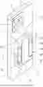
FIG. 1 is a perspective view showing that a portable power bank according to an embodiment of the present invention is coupled with a mobile device;
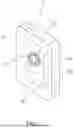
FIG. 2 is a perspective view of the portable power bank of the embodiment of present invention;
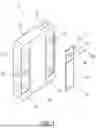
FIG. 3 is an exploded view of the portable power bank of the embodiment of the present invention;
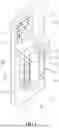
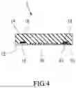
FIG. 4 is a cross-sectional view taken along line 4-4 of FIG. 1; and
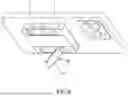
FIGS. 5 and 6 are schematic views showing the portable power bank of the embodiment of the present invention in different states of use.
DETAILED DESCRIPTION OF THE INVENTION
The structure and technical features of the present invention will be detailedly described hereunder by an embodiment and accompany drawings. As shown in FIGS. 1-4, a portable power bank 1 provided in accordance with an embodiment of the present invention is adapted to be coupled with a mobile device 2, such as a mobile phone or tablet computer. The portable power bank 1 is composed of a housing 10, a battery 20, a display 30, a signal receiving module 35, and optionally a support stand 40.
The housing 10 is a flat cube and has a front side 12, a back side 14, and a peripheral side 15. The back side 14 of the housing 10 is used to be coupled with the back 3 of the mobile device 2 by magnetic attraction, anchored engagement, or other proper ways. On the front side 12 o the housing 10, two elongated recesses 16 are provided. In each of the recesses 16, three first magnetic members 18 are embedded. In another embodiment, the recess 16 may not be provided or only one recess 16 may be provided, and the location of the recess 16 may be changed to the periphery side 15. Further, the first magnetic members 18 may be omitted, or one or more magnetic members 18 may be provided, and the location of the magnetic member 18 may be changed to the periphery side 15.
The battery 20 is located inside the housing 10 and capable of charging the mobile device 2. A charging coil 22 is further provided inside the housing 10 in a way that the charging coil 22 is electrically connected with the battery 20, so that the portable power bank 1 can charge the mobile device 2 in a wireless manner. In another embodiment, the portable power bank 1 will charge the mobile device 2 via an electrical wire.
The display 30 is arranged on the front side 12 of the housing 10 and located between the two recesses 16. The display 30 has a width ranging from 32 mm to 56 mm, and a length ranging from 66 mm to 99 mm, such that the aspect ratio of the display 30 is similar to that of the screen 5 of the mobile device 2.
The signal receiving module 35 is installed inside the housing 10 and electrically connected to the display 30. The signal receiving module 35 is configured to be capable of receiving the signal transmitted by the mobile device 2 in a wireless manner in such a way that the display 30 shows a mirror image of an image of the screen 5 of the mobile device 2. The so-called mirror image in the present invention refers to a reverse image in left and right sides. In another embodiment, the signal receiving module 35 can be disposed outside the housing 10.
The support stand 40 is accommodated in one of the recesses 16. The support stand 40 has an abutment portion 42 attracted to the first magnetic members 18, and a support portion 44 that can be moved or bent relative to the abutment portion 42 to change an orientation angle relative to the abutment portion 42. The support portion 44 is pivotally connected to the abutment portion 42 by a pivot 46. A spring 48 is sleeved onto the pivot 46 and arranged between the abutment portion 42 and the support portion 44 in such a way that the support portion 44 can set at a desired angle, such as 30°, 45°, 60°, 75°, 90°, 120°, 135°, 150° or 180°, relative to the abutment portion 42. The abutment portion 42 may be made of a material that can be attracted by the first magnetic members 18, such as iron alloy. In order to enhance the magnetic attraction, the abutment portion 42 may be provided with a second magnetic member 43 that can be magnetically attracted to the first magnetic members 18. The abutment portion 42 is square, so it can still be accommodated and fitted into the recess 16 after being rotated by 90°. When the user wants to stand the mobile device 2 on the table and watch it, he/she can attach the abutment portion 42 to any of the first magnetic members 18, and then adjust the orientation angle between the support portion 44 and the abutment portion 42 and make the terminal end of the support portion 44 stand on the desktop, so that the mobile device 2 can be held at an appropriate angle for easy viewing. As shown in FIGS. 5 and 6, the mobile device 2 can be firmly positioned at an upright or transverse posture. In order to avoid sliding, an anti-slip member 45 may be provided at a terminal end of the support portion 44, and the anti-slip member 45 can be made of rubber, polymer, or other materials, which can make the positioning of the mobile device 2 more reliable. When the support stand 40 is folded, the outer surfaces of the abutment portion 42 and the support portion 44 are flush with the front side 12 of the housing 10. As a result, the appearance of the portable power bank 1 is very smooth, and the support stand 40 is not easy to be caught by foreign objects to fall off.
Since the signal receiving module 35 is configured being capable of receiving signals from mobile devices 2 of different brands, the user does not need to buy a smart watch of the same brand as the mobile device 2. By using the portable power bank 1 to pair a mobile device 2 of various brands and then enable the display 30 to show a mirror image of the screen 5 of the mobile device 2, the display 30 can display the accurate viewing range when the user uses the rear lens 4 to take a selfie, which makes the view taking very convenient for the user.
In addition, the portable power bank 1 can charge the mobile device 2 in a wired or wireless manner, which can greatly reduce the risk of power shortage when the user wants to take pictures or record videos.
It is to be especially mentioned that most of the monitors with mirror display function on the market are large-sized TVs, and are not applied to small-sized displays like the present invention. The portable power bank of the present invention integrates many functions, such as mirror display, wired/wireless charging, and a stand, and thus has great market potential.
Based on the technical features of the present invention, various modifications to the portable power bank 1 may be made. For example, the abutment portion 42 and the support portion 44 of the support stand 40 can be coupled by other ways, and the orientation angle therebetween may be adjusted in a continuous manner, not a discrete manner. Such variations are not to be regarded as a departure from the spirit and scope of the invention, and all such modifications as would be obvious to one skilled in the art are intended to be included within the scope of the following claims.
Claims
What is claimed is:1. A portable power bank for being coupled with a mobile device comprising a screen, the portable power bank comprising:
a housing having a front side and a back side, the back side being adapted to be coupled with the mobile device;
a battery disposed inside the housing for charging the mobile device;
a display disposed at the front side of the housing;
a signal receiving module electrically connected with the display;
wherein the signal receiving module wirelessly receives a signal transmitted by the mobile device to enable the display to show a mirror image of an image of the screen of the mobile device.
2. The potable power bank as claimed in claim 1, wherein the housing is provided with at least one first magnetic element.
3. The portable power bank as claimed in claim 2, wherein the first magnetic member is provided at the front side of the housing.
4. The portable power bank as claimed in claim 2, wherein the housing is provided with a recess in which the first magnetic member is located.
5. The portable power bank as claim in claim 4, further comprising a support stand; the support stand comprises an abutment portion mounted to the housing, and a support portion moveable relative to the abutment portion to change an orientation angle between the abutment portion and the support portion.
6. The portable power bank as claimed in claim 5, wherein the abutment portion of the support stand is magnetically attracted to the first magnetic member.
7. The portable power bank as claimed in claim 5, wherein the support portion of the support stand is provided at a terminal end thereof with an anti-slip member.
8. The portable power bank as claimed in claim 5, wherein the support stand comprises a spring disposed between the abutment portion and the support portion.
9. The portable power bank as claimed in claim 4, further comprising a support stand disposed in the recess; the support stand comprises an abutment portion magnetically attracted to the first magnetic member, and a support portion moveable relative to the abutment portion to change an orientation angle between the abutment portion and the support portion.
10. The portable power bank as claimed in claim 9, wherein the abutment portion of the support stand is provided with a second magnetic member attracted to the first magnetic member.
11. The portable power bank as claimed in claim 9, wherein the support stand comprises a spring disposed between the abutment portion and the support portion.
12. The portable power bank as claimed in claim 1, further comprising a charging coil electrically connected with the battery for enabling the portable power bank to charge the mobile device.
13. The portable power bank as claimed in claim 1, wherein the display has a width ranging from 32 mm to 56 mm, and a length ranging from 66 mm to 99 mm.
Images & Drawings included:

Sources:
- United States Patent and Trademark Office - verify current appl. status at the USPTO↗
Similar patent applications:
- » 20180097537
Multi-purpose portable power bank and/or mobile phone fixing device - » 20180358830
Portable power bank system - » 20130290741
Portable power bank with card reading function - » 20140300311
PORTABLE POWER BANK AND BATTERY BOOSTER - » 20130306726
PORTABLE POWER BANK WITH CARD READING FUNCTION - » 20150033046
Method of power management, portable system and portable power bank - » 20140013128
Portable power bank device with projecting function capable of charging an external device and displaying data from the external device - » 20150288219
Portable Power Bank - » 20150372521
Portable Power Bank - » 20190027949
PORTABLE POWER BANK FOR A SMARTWATCH OR THE LIKE
Recent applications in this class:
- » 20250175022 2025-05-29
CHARGER - » 20250167570 2025-05-22
SHOPPING CART, CHARGING METHOD, AND STORAGE MEDIUM - » 20250158432 2025-05-15
Wireless Power Transfer System For Listening Devices With Expandable Case - » 20250158431 2025-05-15
Wireless Power Transfer System For Listening Devices - » 20250125640 2025-04-17
CHARGING CASE WITH RETENTION MECHANISM FOR RETAINING AND FACILITATING CHARGING OF SMART GLASSES VIA NOSE BRIDGE OF THE SMART GLASSES - » 20250125639 2025-04-17
CHARGING CASE WITH RETENTION MECHANISM FOR RETAINING AND FACILITATING CHARGING OF SMART GLASSES VIA NOSE BRIDGE OF THE SMART GLASSES - » 20250112479 2025-04-03
CHARGER FOR AEROSOL-GENERATING DEVICE WITH SPHERICAL COVER - » 20250112478 2025-04-03
Charging case capable of lighting up automatically - » 20250088016 2025-03-13
Electronic Device Charging Stand with Adjustable Support - » 20250088015 2025-03-13
MOBILE CHARGING DEVICE