PERSONAL WATERCRAFT INTAKE GRATE
US20240425152A1
2024-12-26
18/337,929
2023-06-20
Smart Summary: A new intake grate is designed for personal watercraft to ensure the right amount of water flows to the impeller while keeping debris out. It consists of several long support pieces, each with a front and back end. The front end connects to a mounting plate that attaches to the watercraft's hull. There are gaps between these support pieces that help optimize water flow and block debris. The back end also has a mounting plate that secures it to the hull, ensuring stability and functionality. 🚀 TL;DR
Abstract:
An intake grate for a personal watercraft that is configured to provide a proper waterflow to the impeller of the watercraft and further inhibit debris from egressing therepast. The present invention includes a plurality of longitudinal members having a first end and a second end. Secured to the first end of the longitudinal support members is a forward mounting plate. The forward mounting plate is present on the second side of the longitudinal members and is secured to the hull of the watercraft. The longitudinal members have a void intermediate each longitudinal member wherein the void is optimized to provide a proper waterflow for the impeller and inhibit debris from egressing therepast. Secured to the second end of the longitudinal members is an aft mounting plate wherein the aft mounting plate is fastened to the hull of the watercraft.
Applicant:
Interested in similar patents?
Get notified when new applications in this technology area are published.
Classification:
B63B34/10 » CPC main
Vessels specially adapted for water sports or leisure; Body-supporting devices specially adapted for water sports or leisure Power-driven personal watercraft, e.g. water scooters ; Accessories therefor
Description
FIELD OF THE INVENTION
The present invention relates generally to personal watercraft accessories, more specifically but not by way of limitation, a personal watercraft intake grate that is designed to improve the water flow into the impeller cavity while inhibiting debris from entering thereinto.
BACKGROUND
Personal watercraft popularity has exploded in North America over the last decade. The styles, performance and cost of this type of watercraft has enabled many to begin participation in watersports. While there are many manufactures of personal watercraft, the core design of all is basically the same. Personal watercraft employ an engine that powers a drive shaft wherein the drive shaft has operably coupled thereto an impeller. The impeller is located in a drive shaft housing wherein the rotation of the impeller draws water into the housing and the impeller subsequently expels the water outward through a rear nozzle. The drive shaft housing includes a grate that is operable to cover the opening of the water intake for the drive shaft housing.
While stock impellers and other components function well, many personal watercraft owners change out certain parts to enhance the performance of the personal watercraft. This can include but is not limited to impellers. Impellers operate more efficiently when the current volume of water is being supplied thereto. It is common for the intake grate to be exchanged as an effort to increase water volume flow to the impeller. One issue with these is the existing designs of both stock intake grates and aftermarket intake grates is the inability to provide an increase in water flow as well as inhibit debris from entering the drive shaft housing. Debris such as but not limited to rocks often will enter the drive shaft housing due to intake grate design deficiencies.
Accordingly, there is a need for an intake grate for a personal watercraft that provides proper waterflow to the impeller and further inhibits debris from entering the drive shaft housing.
SUMMARY OF THE INVENTION
It is the object of the present invention to provide a personal watercraft intake grate that is configured to inhibit debris from entering the driveshaft housing of a personal watercraft wherein the present invention is mechanically coupled over the opening to the driveshaft housing.
Another object of the present invention is to provide an intake grate for a personal watercraft configured to provide proper water flow and inhibit debris from egressing therepast wherein the present invention is manufactured from aluminum or similar material.
A further object of the present invention is to provide a personal watercraft intake grate that is configured to inhibit debris from entering the driveshaft housing of a personal watercraft wherein the present invention includes a plurality of longitudinal members.
Yet a further object of the present invention is to provide an intake grate for a personal watercraft configured to provide proper water flow and inhibit debris from egressing therepast that includes a forward mounting plate.
Still another object of the present invention is to provide a personal watercraft intake grate that is configured to inhibit debris from entering the driveshaft housing of a personal watercraft that includes an aft mounting plate secured to the plurality of longitudinal members distal to the forward mounting plate.
An additional object of the present invention is to provide an intake grate for a personal watercraft configured to provide proper water flow and inhibit debris from egressing therepast that further includes a center longitudinal member.
Yet a further object of the present invention is to provide a personal watercraft intake grate that is configured to inhibit debris from entering the driveshaft housing of a personal watercraft wherein the aft mounting plate includes a forward edge that is angular in form.
To the accomplishment of the above and related objects the present invention may be embodied in the form illustrated in the accompanying drawings. Attention is called to the fact that the drawings are illustrative only. Variations are contemplated as being a part of the present invention, limited only by the scope of the claims.
BRIEF DESCRIPTION OF THE DRAWINGS
A more complete understanding of the present invention may be had by reference to the following Detailed Description and appended claims when taken in conjunction with the accompanying Drawings wherein:
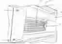
FIG. 1 is a front perspective view of an intake grate according to an embodiment of the invention;
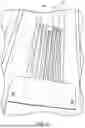
FIG. 2 is a side perspective view of FIG. 1; and
FIG. 3 is a bottom perspective view of FIG. 1.
DETAILED DESCRIPTION
Referring now to the drawings submitted herewith, wherein various elements depicted therein are not necessarily drawn to scale and wherein through the views and figures like elements are referenced with identical reference numerals, there is illustrated an intake grate 100 constructed according to the principles of the present invention.
An embodiment of the present invention is discussed herein with reference to the figures submitted herewith. Those skilled in the art will understand that the detailed description herein with respect to these figures is for explanatory purposes and that it is contemplated within the scope of the present invention that alternative embodiments are plausible. By way of example but not by way of limitation, those having skill in the art in light of the present teachings of the present invention will recognize a plurality of alternate and suitable approaches dependent upon the needs of the particular application to implement the functionality of any given detail described herein, beyond that of the particular implementation choices in the embodiment described herein. Various modifications and embodiments are within the scope of the present invention.
It is to be further understood that the present invention is not limited to the particular methodology, materials, uses and applications described herein, as these may vary. Furthermore, it is also to be understood that the terminology used herein is used for the purpose of describing particular embodiments only, and is not intended to limit the scope of the present invention. It must be noted that as used herein and in the claims, the singular forms “a”, “an” and “the” include the plural reference unless the context clearly dictates otherwise. Thus, for example, a reference to “an element” is a reference to one or more elements and includes equivalents thereof known to those skilled in the art. All conjunctions used are to be understood in the most inclusive sense possible. Thus, the word “or” should be understood as having the definition of a logical “or” rather than that of a logical “exclusive or” unless the context clearly necessitates otherwise. Structures described herein are to be understood also to refer to functional equivalents of such structures. Language that may be construed to express approximation should be so understood unless the context clearly dictates otherwise.
References to “one embodiment”, “an embodiment”, “exemplary embodiments”, and the like may indicate that the embodiment(s) of the invention so described may include a particular feature, structure or characteristic, but not every embodiment necessarily includes the particular feature, structure or characteristic.
Referring in particular to the Figures submitted herewith, the intake grate 100 is manufactured from a durable rigid material such as but not limited to aluminum. It should be understood within the scope of the present invention that the intake grate could be manufactured in alternate sizes and shapes in order to be operably coupled to different sizes and models of personal watercraft. The intake grate 100 includes a first end 5 and second end 10 wherein the intake grate 100 further includes a plurality of longitudinal members 20. The longitudinal members 20 are elongated form being rectangular in shape having a first end 21 and second end 22. The longitudinal members in a preferred embodiment are one-quarter inch in thickness but it should be understood within the scope of the present invention that the longitudinal members could be manufactured in alternate thicknesses. Intermediate each longitudinal member 20 is a void 30. Voids 30 are provided to permit water to flow therethrough and further inhibit debris from egressing therepast. In a preferred embodiment of the present invention, the voids 30 have a width of seven-eighths of an inch. While a preferred parameter has been disclosed for the voids 30, it should be understood within the scope of the present invention that the voids 30 could be provided in alternate widths.
The longitudinal members 20 are secured to the forward mounting plate 40 proximate the first end 21. The first ends 21 are secured to the forward mounting plate 40 utilizing suitable techniques such as but not limited to welding. The forward mounting plate 40 is located on the second side of the longitudinal members 20 wherein the forward mounting plate 40 is adjacent the hull 99. A central longitudinal member 27 is provided in the plurality of longitudinal members 20 and is manufactured to have a length less than that of the remaining longitudinal members 20. The central longitudinal member 27 includes first end 28 that is secured to the forward mounting plate 40 adjacent fastener 45 wherein the shortened length of the central longitudinal member 27 accommodates placement of the fastener 45 to facilitate securing of the forward mounting plate 40 to the hull 99.
Secured to the second ends 22 of the longitudinal members 20 is the aft mounting plate 50. The aft mounting plate 50 is manufactured from aluminum or similar material and has a width that is greater than that of the forward mounting plate 40. The aft mounting plate 50 is configured to be mounted directly to the hull 99 and has a thickness that permits being superposed any existing element that may be on the hull 99. The aft mounting plate 50 includes a forward perimeter edge 53 wherein the forward perimeter edge 53 is angular in form. The aforementioned shape of the forward perimeter edge 53 is designed so as to inhibit any drag from the water ensuing mounting the intake grate 100 to a personal watercraft. The aft mounting plate 50 is secured to the hull 99 utilizing fasteners 57,58. It is contemplated within the scope of the present invention that the aft mounting plate 50 could be manufactured in alternate sizes and shapes to be operably coupled to different models of personal watercraft.
In the preceding detailed description, reference has been made to the accompanying drawings that form a part hereof, and in which are shown by way of illustration specific embodiments in which the invention may be practiced. These embodiments, and certain variants thereof, have been described in sufficient detail to enable those skilled in the art to practice the invention. It is to be understood that other suitable embodiments may be utilized and that logical changes may be made without departing from the spirit or scope of the invention. The description may omit certain information known to those skilled in the art. The preceding detailed description is, therefore, not intended to be limited to the specific forms set forth herein, but on the contrary, it is intended to cover such alternatives, modifications, and equivalents, as can be reasonably included within the spirit and scope of the appended claims.
Claims
What is claimed is:1. An intake grate for a personal watercraft comprising:
a plurality of longitudinal members, said plurality of longitudinal members having a first end and a second end, said plurality of longitudinal members being elongated in form, said plurality of longitudinal members having a void intermediate each of said plurality of longitudinal members, said plurality of longitudinal members including a central longitudinal member, said central longitudinal member being centrally disposed among said plurality of longitudinal members, said central longitudinal member having a length that is less than a length of the plurality of longitudinal members;
a forward mounting plate, said forward mounting plate being secured to said plurality of longitudinal members proximate the first end thereof, said forward mounting plate being secured to a second side of said plurality of longitudinal members, said forward mounting plate being adjacent a hull of the personal watercraft;
an aft mounting plate, said aft mounting plate being secured to said plurality of longitudinal members proximate said second end thereof, said aft mounting plate having a width that is greater than a width of the plurality of longitudinal members, said aft mounting plate having a forward perimeter edge, said forward perimeter edge of said aft mounting plate being angled in form.
2. The intake grate for a personal watercraft as recited in claim 1, wherein the voids intermediate each of said plurality of longitudinal members is seven-eighths of an inch.
3. The intake grate for a personal watercraft as recited in claim 2, wherein each of said plurality of longitudinal members has a thickness that is one-quarter of an inch.
4. The intake grate for a personal watercraft as recited in claim 3, wherein the aft mounting plate is operably coupled to the hull of the personal watercraft.
5. The intake grate for a personal watercraft as recited in claim 4, wherein said intake grate is manufactured from aluminum.
Images & Drawings included:

Sources:
- United States Patent and Trademark Office - verify current appl. status at the USPTO↗
Recent applications in this class:
- » 20250026455 2025-01-23
Method of Converting a Jet Board into a Personal Watercraft (PWC) Using - » 20240425151 2024-12-26
PERSONAL WATERCRAFT - » 20240417041 2024-12-19
PERSONAL WATERCRAFT - » 20240417040 2024-12-19
PERSONAL WATERCRAFT - » 20240409191 2024-12-12
ARTICLE HOLDING DEVICE AND PERSONAL WATERCRAFT - » 20240400166 2024-12-05
PERSONAL WATERCRAFT - » 20240343354 2024-10-17
HYDROJET PROPULSION SYSTEM - » 20240190539 2024-06-13
WATER SPORTS APPARATUS COMPRISING A WATER VEHICLE AND USE OF A WATER VEHICLE - » 20240116603 2024-04-11
Method and Apparatus for Protecting a Surface of a Watercraft - » 20230382502 2023-11-30
Hydrojet propulsion system