WATER HEATERS WITH INDICATION SYSTEMS CONFIGURED TO PROVIDE ONE OR MORE ALERTS TO USERS
US20250060134A1
2025-02-20
18/782,257
2024-07-24
Smart Summary: A water heating system has a sensor that can find problems in the heating process. It also includes a timer that tracks how long hot water is being used. The system has a controller that collects information from both the sensor and the timer. When certain conditions are met, the controller can change the water flow or temperature for a short period. This change serves as an alert to inform users about the issue. 🚀 TL;DR
Abstract:
A water heating system is disclosed. The water heating system may include a sensor configured to detect an anomaly in the water heating system, and a timer configured to detect hot water usage time duration. The water heating system may further include a controller configured to obtain inputs from the sensor and the hot water usage time duration from the timer. The controller may be further configured to determine that a predetermined condition is met based on the inputs or the hot water usage time duration. Responsive to a determination that the predetermined condition is met, the controller may be configured to modify a water flow or an output water temperature for a predefined time duration to provide an alert signal to a user.
Inventors:
- Christopher Mark Hayden 16 🇺🇸 Shelton, CT, United States
- Harsha Satyanarayana 13 🇺🇸 Norwalk, CT, United States
Applicant:
Interested in similar patents?
Get notified when new applications in this technology area are published.
Classification:
F24H15/395 » CPC main
Control of fluid heaters characterised by control outputs; characterised by the components to be controlled Information to users, e.g. alarms
F24H15/104 » CPC further
Control of fluid heaters characterised by the purpose of the control Inspection; Diagnosis; Trial operation
F24H15/269 » CPC further
Control of fluid heaters characterised by control inputs Time, e.g. hour or date
F24H15/31 » CPC further
Control of fluid heaters characterised by control outputs; characterised by the components to be controlled; Control of valves of valves having only one inlet port and one outlet port, e.g. flow rate regulating valves
F24H15/315 » CPC further
Control of fluid heaters characterised by control outputs; characterised by the components to be controlled; Control of valves of mixing valves
F24H15/355 » CPC further
Control of fluid heaters characterised by control outputs; characterised by the components to be controlled Control of heat-generating means in heaters
Description
CROSS-REFERENCE TO RELATED APPLICATIONS
This applications claims priority to and the benefit of U.S. provisional application No. 63/519,611, filed Aug. 15, 2023, which is hereby incorporated by reference herein in its entirety.
FIELD
The present disclosure relates to water heaters and more particularly to water heaters with indication systems that are configured to provide an alert to a user by modifying water flow or water temperature when a condition or an anomaly is detected in the water heater or when water usage exceeds a threshold.
BACKGROUND
Water heating systems are generally used to provide a supply of heated water. Water heating systems are used in a variety of applications including residential, commercial, and industrial applications. In some modern water heating systems, an alert may be provided to a user when there may be an anomaly with the water heating system. For example, the water heating system may provide a visual or an audible alert to the user when there may be a leak in the water heating system. In some instances, the alerts may be provided at the water heating system. In other instances, the alerts may be provided to a user device, such as a smart phone or the like. The user may receive/view the alert and may take appropriate action to rectify the anomaly.
While such alerts may prompt the user to rectify the anomaly, there may be instances where the user may not notice the alerts. For example, the user may not notice the alerts when the water heating system may be disposed away from the user (such as in a mechanical room located in a basement) or the user does not have their user device.
BRIEF DESCRIPTION OF THE DRAWINGS
The detailed description is set forth with reference to the accompanying drawings. The use of the same reference numerals may indicate similar or identical items. Various embodiments may utilize elements and/or components other than those illustrated in the drawings, and some elements and/or components may not be present in various embodiments. Elements and/or components in the figures are not necessarily drawn to scale. Throughout this disclosure, depending on the context, singular and plural terminology may be used interchangeably.
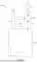
FIG. 1 depicts a schematic illustration of an example water heating system in accordance with one or more embodiments of the present disclosure.
FIG. 2 depicts a block diagram of an electronics unit in accordance with one or more embodiments of the present disclosure.
FIG. 3 depicts a flow diagram of an example method to control a water heating system in accordance with one or more embodiments of the present disclosure.
FIG. 4 depicts a flow diagram of an example method to control a water heating system in accordance with one or more embodiments of the present disclosure.
DETAILED DESCRIPTION
The present disclosure is directed towards a water heating system (or system) that may be configured to provide an alert to a user when a predetermined condition may be met. For example, the system may provide the alert to the user when an anomaly (such as leakage in a heating system water tank) may be detected in the system or when water usage exceeds a threshold. In some aspects, the system may provide the alert by modifying a flow or a temperature of water output from the system for a predefined time duration. Stated another way, the system may use “water signals” or water as a communication means to provide the alert to the user.
In some aspects, the system may modify the temperature of water output from the system by controlling a mixing valve that may be configured to mix cold water from a cold water supply and hot water from the heating system water tank. In further aspects, the system may modify the water temperature by controlling a heating element (such as a gas burner, resistive heating element, and/or a heat pump) of the water heating system. For example, the system may modify the temperature of the water (e.g., by generating constant or pulsating water temperatures) that may provide the alert to the user. In additional aspects, the system may modify the flow of water output from the system by controlling a shut-off valve that may be configured to control water flow out from the system. For example, the system may modify the water flow to generate pulsating water flow that may provide the alert to the user.
In certain embodiments, the system may include a detection unit. In some embodiments, the detection unit may be a sensor configured to detect the anomaly in the system. For example, the system may include a leak sensor that may detect water leakage in the system. Any suitable sensor may be used that is configured to detect one or more operational parameters of the water heating system, and based on the operational parameters of the water heating system, one or more alerts may be sent to a user through the control (e.g., modifying the flow or temperature) of the water. In certain embodiments, the detection unit may include a timer configured to detect water usage or hot water usage time duration. The system may be configured to determine that a predetermined condition is met when the sensor detects any anomaly or when the hot water usage time duration exceeds the threshold. For example, the system may determine that the predetermined condition may be met when the user uses a water outlet (e.g., takes a shower) for a time duration that may exceed a predefined hot water usage time duration.
In this manner, the present disclosure is directed to a water heating system that may provide an alert or an indication to a user even when the user may be physically away from the water heating system or a smart device that is connected to the water heating system, via the local hot water output (e.g., shower, faucet). For example, the user may receive the alert even if the water heating system is located in a home basement, and the user is taking a shower in an upstairs bathroom. In some instances, the user may get the alert when there is a leak in the system and may accordingly take remedial action in a timely manner. In addition, the system may provide the alert when the user is using a water outlet (e.g., takes a shower) for a time duration longer than a predefined time duration. Thus, the system may assist in conserving water.
Although certain examples of the disclosed technology are explained in detail herein, it is to be understood that other examples, embodiments, and implementations of the disclosed technology are contemplated. Accordingly, it is not intended that the disclosed technology is limited in its scope to the details of construction and arrangement of components expressly set forth in the following description or illustrated in the drawings. The disclosed technology can be implemented in a variety of examples and can be practiced or carried out in various ways. In particular, the presently disclosed subject matter is described in the context of being a water heating system with an indication system. The present disclosure, however, is not so limited, and can be applicable in other contexts. Further, the present disclosure, for example and not limitation, can be applied to water heating systems such as residential water heaters, commercial water heaters, industrial water heaters, and other water heating systems configured to heat water. Furthermore, the present disclosure can include other fluid heating systems configured to heat a fluid other than water such as fluid heaters used in industrial applications. Such implementations and applications are contemplated within the scope of the present disclosure. Accordingly, when the present disclosure is described in the context of being a water heating system with the indication system, it will be understood that other implementations can take the place of those referred to.
Although the term “water” is used throughout this specification, it is to be understood that other fluids may take the place of the term “water” as used herein. Therefore, although described as a water heating system, it is to be understood that the system and methods described herein can apply to fluids other than water. Further, it is also to be understood that the term “fluid” can replace the term “water” as used herein unless the context clearly dictates otherwise.
Turning now to the drawings, FIG. 1 depicts a schematic illustration of an example water heating system 100 (system 100) in accordance with one or more embodiments of the present disclosure. The system 100 may heat water to be used in a residential, a commercial, or an industrial application. The system 100 may be of any suitable size or configuration based on the water heating system application and user needs.
In certain embodiments, the system 100 may include a water tank 105 that may be disposed in a system interior portion. The water tank 105 may be configured to receive a supply of cold water. The water tank may store the water. The water tank 105 may be made of any material, such as steel, copper, plastic, composites, and/or the like. The water tank 105 may be insulated to maintain water temperature inside the water tank 105. The water tank 105 may be of any suitable size, shape, or configuration. In some instances, the water tank 105 may be omitted. For example, the system 100 may be a tankless water heater (or on-demand water heater) and may not necessarily require the water tank 105. The tankless water heater may heat water instantaneously without storing the water in a water tank, e.g., the water tank 105.
The system 100 further may include a heating element 110 that may be configured to heat water in the water tank 105 to a desired water temperature. In some instances, such as in tankless water heater systems, the heating element 110 may heat water on demand from a cold water conduit or the like. The heating element 110 may include any type of available heating systems that are known within the art. For example, the heating element 110 may include an electric heating element, a gas burner, a heat pump, a renewable energy heater (e.g., a solar and/or wind heater), and/or a combination thereof or the like.
The system 100 may further include a cold water conduit 115, a hot water conduit 120, and an outlet water conduit 125. The cold water conduit 115 may be configured to receive cold water from an independent source located outside the system 100 (e.g., a supply of cold water from a utility, well, or the like) and supply the cold water to the water tank 105. The hot water conduit 120 may be configured to receive heated water from the water tank 105. The outlet water conduit 125 may be configured to output water to one or more outlets, such as to faucets, spigots, sinks, showers, bathtubs, etc. In some aspects, the outlet water conduit 125 may be configured to output heated/hot water at a desired water temperature.
The system 100 may further include a mixing valve 130 that may be configured to receive a bleed supply of cold water from the cold water conduit 115 and hot water from the hot water conduit 120. The mixing valve 130 may be configured to mix the bleed supply of cold water from the cold water conduit 115 and hot water from the hot water conduit 120 at a predefined ratio to output blended water. In some instances, the ratio may be adjustable. The mixing valve 130 may be configured to blend the cold water and the hot water at the desired water temperature and output the blended water or temperature-regulated water to one or more outlets via the outlet water conduit 125.
The system 100 may further include a shut-off valve 135 that may be configured to at least partially shut water output from the system 100. For example, the shut-off valve 135 may stop/regulate water flow from the outlet water conduit 125 when there may be a leak in the water tank 105 or when a predetermined condition may be met. In some aspects, the system 100 may further include an additional shut-off valve that may be configured to shut water intake into the system 100 when there may be leakage in the water tank 105 or when the predetermined condition may be met. For example, the additional shut-off valve may be disposed about and stop water flow from the cold water conduit 115 (e.g., to the water tank 105 (or heating element in a tankless system) and the outlet water conduit 125) when the system 100 is being cleaned or when the water tank 105 develops a leak or other undesirable condition.
The system 100 may further include an electronics unit 140 that may include one or components. For example, the electronics unit 140 may include one or more sensors (shown as sensor 205 in FIG. 2), a timer (shown as timer 210 in FIG. 2), and a controller (shown as controller 215 in FIG. 2). The sensors may be configured to detect an anomaly or other parameters of the system 100. In some aspects, the sensors may include a leak sensor that may be configured to detect leakage in the system 100 (e.g., in the water tank 105).
The sensors may further include temperature sensor(s), flow rate sensor(s), etc. The temperature sensor(s) may be configured to detect water temperature (e.g., temperature of water entering the water tank 105 from the cold water conduit 115, temperature of water present in the water tank 105, and/or temperature of water flowing out from the outlet water conduit 125). The temperature sensor(s) may include thermocouples, resistor temperature detectors, thermistors, infrared sensors, semiconductors, or any other type of sensor that would be appropriate for a given use or application. The flow sensor(s) may be configured to determine a rate of water flow into the water tank 105 and/or water dispensed from the system 100.
A person ordinarily skilled in the art may appreciate that the sensors may include additional sensors or components, which may enable efficient system working. Examples of such additional sensors or components include, but are not limited to, a pressure sensor, a scale, a voltmeter, an ammeter, a power meter, an ohmmeter, a resistance temperature detector, environment condition sensors including ambient air temperature sensor, humidity sensors, and/or the like. These additional sensors or components are not shown in FIG. 1 for the sake of simplicity and conciseness.
In certain embodiments, the timer may be configured to detect hot water usage time duration. For example, the timer may be configured to detect a time duration for which water may be dispensed continuously from the outlet water conduit 125. In some instances, the timer may be in communication with a flow sensor or the like about the outlet water conduit 125 to determine how long water is flowing out of the outlet water conduit 125.
The controller may be communicatively coupled with the sensors and the timer. The controller may be configured to receive inputs from the sensors and the timer and control/modify operations of various system components based on the received inputs. In some aspects, the controller may control/modify operations of one or more system components to provide an indication or an alert to a user when a predetermined condition may be met. For example, the controller may control/modify operations of one or more system components when there may be a leak or an anomaly in the system 100 and/or when water may be continuously dispensed from the outlet water conduit 125 for more than a predefined time duration.
In some aspects, the controller may determine that there may be a leak/anomaly in the system 100 based on the inputs received from the sensors. Similarly, the controller may determine that water may be continuously dispensed from the outlet water conduit 125 for more than the predefined time duration based on the inputs received from the timer. In an exemplary aspect, water may be continuously dispensed from the outlet water conduit 125 for more than the predefined time duration when the user may taking shower using hot water from the system 100 for more than the predefined time duration (e.g., more than 10 or 15 minutes).
In certain embodiments, responsive to a determination that the predetermined condition may be met, the controller may modify the water flow and/or the output water temperature for a predefined time duration to provide an alert to the user. For example, when the user may be taking shower for more than the predefined time duration, the controller may modify the water flow and/or the output water temperature to provide an alert or a “water signal” to the user to stop the shower (thereby assisting in conserving water). Similarly, when the controller provides the water signal to the user, the user may understand that the system 100 may have developed an anomaly (e.g., leakage). In some instances, the water signal may be different depending on the alert. For example, the flow may be pulsated when a leak is detected. In other instances, the temperature of the water may be modulated if the user is outputting water (e.g., taking a shower) for more than the predefined time duration. Responsive to receiving the water signal, the user may stop using the system and/or rectify the anomaly. Since the user receives the alert or the water signal while the user may be using the system 100, probability of user missing the alert is greatly reduced (even if the system 100 is disposed away from the user, e.g., in a mechanical room or a basement).
FIG. 2 depicts a block diagram of an electronics unit 200 in accordance with one or more embodiments of the present disclosure. In certain embodiments, the electronics unit 200 may be same as the electronics unit 140 described in conjunction with FIG. 1. In some instances, the electronics unit 200 may include one or more sensors 205 (or a sensor 205), a timer 210, and a controller 215. The sensor 205, the timer 210, and the controller 215 may be same as the sensors, the timer, and the controller described above in conjunction with FIG. 1.
In certain embodiments, the controller 215 may include a plurality of components including, but not limited to, a memory 220, a processor 225, and a communication interface 230. The controller 215 may be a computing device configured to receive data, determine actions based on the received data, and output a control signal instructing one or more water heating system components to perform one or more actions. As described above, the controller 215 may be in communication with at least some of the water heating system components.
In some aspects, the controller 215 may be configured to send and receive wireless or wired signals, and the signals may be analog or digital signals. The wireless signals may include Bluetooth®, BLE, WiFi®, ZigBee®, infrared, microwave radio, or any other type of wireless communication signals as may be suitable for a particular water heating system application. The hard-wired signals can include communication signals between any directly wired connections between the controller 215 and other water heating system components. For example, the controller 215 can have a hard-wired 24 Volts Direct Current (VDC) connection to the sensor 205 and/or the timer 210.
Alternatively, the controller 215 may communicate with the sensor 205 and/or the timer 210 via a digital connection. The digital connection can include a connection such as an Ethernet or a serial connection and can utilize any suitable communication protocol for the water heating system application, such as Modbus, fieldbus, PROFIBUS, SafetyBus, Ethernet/IP, and/or the like. Furthermore, the controller 215 can utilize a combination of wireless, hard-wired, and analog or digital communication signals to communicate with and control the various water heating system components. A person ordinarily skilled in the art may appreciate that the above configurations are given merely as non-limiting examples and the actual configuration can vary depending on the particular water heating system application.
The memory 220 may be configured to store a program and/or instructions associated with the functions and methods described herein. The processor 225 may be configured to execute the program and/or instructions stored in the memory 220. The memory 220 can include one or more suitable types of memory (e.g., volatile or non-volatile memory, random access memory (RAM), read only memory (ROM), programmable read-only memory (PROM), erasable programmable read-only memory (EPROM), electrically erasable programmable read-only memory (EEPROM), magnetic disks, optical disks, floppy disks, hard disks, removable cartridges, flash memory, a redundant array of independent disks (RAID), and the like) for storing files including the operating system, application programs (including, for example, a web browser application, a widget or gadget engine, and or other applications, as necessary), executable instructions and data. One, some, or all of the processing techniques or methods described herein can be implemented as a combination of executable instructions and data within the memory 220.
The communication interface 230 may be configured to send or receive communication signals between the various water heating system components. Communication interface 230 can include hardware, firmware, and/or software that allows the processor 225 to communicate with the other components via wired or wireless networks, whether local or wide area, private or public, as known in the art. Communication interface 230 can also provide access to a cellular network, the Internet, a local area network, or another wide-area network as suitable for the particular water heating system application.
Additionally, the controller 215 may have or be in communication with a user interface 235 (which may be, e.g., a water heating system Human Machine Interface (HMI)) for displaying water heating system information and receiving inputs from the user. The user interface 235 may be installed locally on the water heating system 100 (e.g., on a water heating system outer surface) or on an app of a user device. The user, for example, can view water heating system data on the user interface 235 and input data or commands to the controller 215 via the user interface 235. For example, the user can view water heating system temperature settings (or any other setting) on the user interface 235 and provide inputs to the controller 215 via the user interface 235 to change the settings. In an exemplary aspect, the user may provide information associated with the desired water temperature of heated water, water usage/demand, desired time to heat the water, maximum time duration to use hot water (e.g., during a shower), etc. to the controller 215 via the user interface 235.
In some aspects, the controller 215 may obtain the inputs from the sensor 205 and the timer 210 and may be configured to control the heating element 110, the mixing valve 130, and/or the shut-off valve 135 via one or more actuators associated therewith to modify the water flow and/or the water temperature for the predefined time duration. The controller 215 may control the above-mentioned components to provide an alert to the user, for example, by providing “water signals,” when a predefined condition may be met. For example, the controller 215 may control the above-mentioned components when there may be an issue/anomaly with the system 100 or when the user has used the system (e.g., taking a shower) for a time duration longer than a predefined time duration. In some aspects, the user may pre-set the predefined time duration by using the user interface 235.
FIG. 3 depicts a flow diagram of an example first method 300 to control the water heating system 100 in accordance with the present disclosure. FIG. 3 may be described with continued reference to prior figures, including FIGS. 1-2. The following process is exemplary and not confined to the steps described hereafter. Moreover, alternative embodiments may include more or less steps that are shown or described herein and may include these steps in a different order than the order described in the following example embodiments.
The method 300 may start at step 302. At step 304, the method 300 may include obtaining, by the controller 215, an input from the timer 210. In some aspects, the controller 215 may obtain the input periodically at a specific frequency (e.g., every 5 seconds or 10 seconds). Any suitable frequency may be used. The input from the timer 210 may indicate a time duration for which water may be continuously dispensing from the outlet water conduit 125. For example, a flow sensor may indicate water is flowing out of the outlet water conduit 125, and the timer 210 may track how long water is flowing. At step 306, the method 300 may include determining, by the controller 215, whether the hot usage time duration (i.e., time duration of dispensing of water) may be greater than a predefined threshold time duration based on the input from the timer 210. Stated another way, the controller 215 may determine whether the user may be using hot water from the system 100 for a time duration greater than the predefined threshold time duration. The predefined threshold time may be associated with the maximum time duration to use hot water from the system 100, which may be set or adjustable by the user via the user interface 235. For example, based on the input from the timer 210, the controller 215 may determine whether the user may be using hot water from the system 100 (e.g., taking a shower) for more than 10 or 15 minutes.
Responsive to a determination that the user may be using the water for a time duration less than the predefined threshold time, the method 300 may move back to the step 304. Alternatively, responsive to a determination that the user may be using the water for a time duration greater than the predefined threshold time duration, the method 300 may move to step 308.
At step 308, the method 300 may include performing, by the controller 215, a first predefined action. In some aspects, the first predefined action may include modifying the output water temperature for a predefined time duration (e.g., 5 or 10 seconds) and then returning to an original water temperature (e.g., the desired water temperature set by the user). Specifically, the controller 215 may control the mixing valve 130 and/or the heating element 110 via one or more actuators to modify the temperature of the water that may be dispensed from the outlet water conduit 125. For example, the user may set the desired water temperature at 120 degrees Fahrenheit and may set the predefined threshold time duration to 10 minutes. When the user may be using hot water from the system 100 for more than 10 minutes, the controller 215 may modify the output water temperature to drop from 120 degrees Fahrenheit to 90-110 degrees Fahrenheit for 2-10 seconds and then return the water temperature to 120 degrees Fahrenheit. Any suitable temperature difference and time duration may be used. In this manner, the controller 215 may modify the water temperature to indicate to the user (who may feel the difference in temperature) that the user may be using hot water from the system 100 (e.g., taking a shower) for a long time duration.
In other aspects, the first predefined action may include modifying the water flow. For example, the controller 215 may control the shut-off valve 135 via one or more actuators to generate/provide pulsating water output. For example, the controller 215 may partially or wholly turn off and on the shut-off valve 135 multiple times (e.g., 3 times) for a predefined time duration (e.g., 1-10 seconds or fractions of second) to generate pulsating water. The pulsating water may transmit an alert to the user that the user may be using hot water from the system 100 (e.g., taking a shower) for a long time duration. In some instances, both the temperature and the flow rate may be modified at the same time. For example, colder water may be pulsated to transmit an alert to the user that the user may be using hot water from the system 100. In some aspects, the controller 215 may perform the first predefined action such that the user (who may be receiving the hot water via the local hot water outlet/output that may be located at some distance from the system 100) may feel/receive the alert or the indication. For example, the controller 215 may modify the output water temperature to drop from 120 degrees Fahrenheit to 90-110 degrees Fahrenheit for at least 2 seconds (e.g., a minimum threshold) so that the user may receive the indication. The minimum threshold may consider the heat loss that may happen while the hot water gets supplied from the system 100 to the local hot water outlet/output. Similarly, the controller 215 may modify the water flow for at least 2 or 5 seconds (as an example) so that the user may receive the indication.
In further aspects, the controller 215 may repeat the first predetermined action, for example, modify the water temperature/flow every 10 seconds, 30 seconds, or 1 minute to continue to provide alerts to the user till the user shuts off the shower. Any suitable time duration may be used. In additional aspects, as noted above, the controller 215 may provide the alert to the user by modifying the water temperature as well as modifying the water flow. For example, the controller 215 may first provide the alert by modifying the water flow, and after a set amount of time, the controller 215 may provide the alert by modifying the water temperature (or vice-versa). In other instances, as noted above, the water temperature/flow may be modified at the same time. The method 300 may then move to step 310, at which the method 300 may end.
FIG. 4 depicts a flow diagram of an example second method 400 to control the water heating system 100 in accordance with the present disclosure. FIG. 4 may be described with continued reference to prior figures, including FIGS. 1-3. The following process is exemplary and not confined to the steps described hereafter. Moreover, alternative embodiments may include more or less steps that are shown or described herein and may include these steps in a different order than the order described in the following example embodiments.
The method 400 may start at step 402. At step 404, the method 400 may include obtaining, by the controller 215, an input from the sensor 205. In some aspects, the controller 215 may obtain the input periodically at a specific frequency (e.g., every 10 seconds or 30 seconds). Any suitable frequency may be used. At step 406, the method 400 may include determining, by the controller 215, a condition of the water heating system 100, such as whether there may be an anomaly in the water heating system 100 based on the input from the sensor 205. For example, the controller 215 may determine if there is a leak in the water heating system 100 based on the input received from the sensor 205. In other instances, the sensor 205 may determine other parameters of the water heating system 100, which may dictate the issuance of an alert as indicated herein.
Responsive to a determination that there may be no anomaly in the system 100, the method 400 may move back to the step 404. Alternatively, responsive to a determination that there may be an anomaly (e.g., leakage) in the system 100, the method 400 may move to step 408.
At step 408, the method 400 may include performing, by the controller 215, a second predefined action. The second predefined action may be the same as the first predefined action. In some aspects, the second predefined action may include modifying water temperature for a predefined time duration (such as 10 seconds) and returning to an original water temperature (e.g., the desired water temperature set by the user). Specifically, the controller 215 may control the mixing valve 130 and/or the heating element 110 via one or more actuators to modify the water temperature. For example, the user may set the desired water temperature at 120 degrees Fahrenheit. When there is a leak in the water heating system 100 (or any other anomaly), the controller 215 may modify the water temperature to drop from 120 degrees Fahrenheit to 110 degrees Fahrenheit for 2, 5, or 10 seconds and then return the water temperature to 120 degrees Fahrenheit. Any suitable temperature difference and time duration may be used. In this manner, the controller 215 may modify the water temperature to indicate to the user that there may be some issue with the system 100.
In other aspects, the second predefined action may include modifying water flow. For example, the controller 215 may control the shut-off valve 135 via one or more actuators to generate pulsating water. For example, the controller 215 may turn off and on the shut-off valve 135 multiple times (e.g., 3 times) to generate pulsating water. The pulsating water may transmit an alert to the user to indicate that there may be some issue with the system 100. In some instances, both the temperature and the flow rate may be modified at the same time. For example, colder water may be pulsated to transmit an alert to the user that there may be some issue with the system 100.
In further aspects, the controller 215 may repeat the second predetermined action, for example, modify the water temperature/flow every 10 second, 30 second, or minute to continue to provide alerts to the user. Any suitable time duration may be used. In further aspects, the controller 215 may provide alerts to the user by modifying the water temperature as well as modifying the water flow. For example, the controller 215 may first provide the alert by modifying the water flow and after one minute the controller 215 may provide the alert by modifying the water temperature (or vice-versa). The method 400 may then move to step 410, at which the method 400 may end. In other instances, as noted above, the water temperature/flow may be modified at the same time.
In the above disclosure, reference has been made to the accompanying drawings, which form a part hereof, which illustrate specific implementations in which the present disclosure may be practiced. It is understood that other implementations may be utilized, and structural changes may be made without departing from the scope of the present disclosure. References in the specification to “one embodiment,” “an embodiment,” “an example embodiment,” etc., indicate that the embodiment described may include a particular feature, structure, or characteristic, but every embodiment may not necessarily include the particular feature, structure, or characteristic. Moreover, such phrases are not necessarily referring to the same embodiment. Further, when a feature, structure, or characteristic is described in connection with an embodiment, one skilled in the art will recognize such feature, structure, or characteristic in connection with other embodiments whether or not explicitly described.
It should also be understood that the word “example” as used herein is intended to be non-exclusionary and non-limiting in nature. More particularly, the word “example” as used herein indicates one among several examples, and it should be understood that no undue emphasis or preference is being directed to the particular example being described.
With regard to the processes, systems, methods, heuristics, etc. described herein, it should be understood that, although the steps of such processes, etc. have been described as occurring according to a certain ordered sequence, such processes could be practiced with the described steps performed in an order other than the order described herein. It further should be understood that certain steps could be performed simultaneously, that other steps could be added, or that certain steps described herein could be omitted. In other words, the descriptions of processes herein are provided for the purpose of illustrating various embodiments and should in no way be construed so as to limit the claims.
Accordingly, it is to be understood that the above description is intended to be illustrative and not restrictive. Many embodiments and applications other than the examples provided would be apparent upon reading the above description. The scope should be determined, not with reference to the above description, but should instead be determined with reference to the appended claims, along with the full scope of equivalents to which such claims are entitled. It is anticipated and intended that future developments will occur in the technologies discussed herein, and that the disclosed systems and methods will be incorporated into such future embodiments. In sum, it should be understood that the application is capable of modification and variation.
All terms used in the claims are intended to be given their ordinary meanings as understood by those knowledgeable in the technologies described herein unless an explicit indication to the contrary is made herein. In particular, use of the singular articles such as “a,” “the,” “said,” etc., should be read to recite one or more of the indicated elements unless a claim recites an explicit limitation to the contrary. Conditional language, such as, among others, “can,” “could,” “might,” or “may,” unless specifically stated otherwise, or otherwise understood within the context as used, is generally intended to convey that certain embodiments could include, while other embodiments may not include, certain features, elements, and/or steps. Thus, such conditional language is not generally intended to imply that features, elements, and/or steps are in any way required for one or more embodiments.
Claims
That which is claimed is:1. A water heating system comprising:
a detection unit configured to detect an anomaly in the water heating system or a hot water usage time duration; and
a controller communicatively coupled to the detection unit, wherein the controller is configured to:
obtain inputs from the detection unit;
determine that a predetermined condition is met based on the inputs; and
modify, based on the predetermined condition being met, a water flow and/or an output water temperature for a predefined time duration to provide an alert signal to a user.
2. The water heating system of claim 1, wherein the detection unit is a sensor or a timer.
3. The water heating system of claim 2, wherein the predetermined condition is met when the sensor detects the anomaly.
4. The water heating system of claim 1, wherein the predetermined condition is met when the hot water usage time duration exceeds a first threshold.
5. The water heating system of claim 1 further comprising a mixing valve configured to control a mixture of cold water and hot water from the water heating system.
6. The water heating system of claim 5, wherein the controller is configured to modify the output water temperature by controlling the mixing valve.
7. The water heating system of claim 1 further comprising a heating element configured to control heating of water in the water heating system.
8. The water heating system of claim 7, wherein the controller is configured to modify the output water temperature by controlling the heating element.
9. The water heating system of claim 1 further comprising a shut-off valve configured to control water flow out of the water heating system.
10. The water heating system of claim 9, wherein the controller is configured to modify the water flow by controlling the shut-off valve.
11. The water heating system of claim 10, wherein the controller is configured to modify the water flow by providing pulsating water output.
12. The water heating system of claim 1, wherein the water heating system is a tankless water heater.
13. The water heating system of claim 2 further comprising a water tank to store water, wherein the sensor is a leak sensor configured to detect leakage in the water tank.
14. A water heating method comprising:
obtaining, by a controller, inputs from a sensor, wherein the sensor is configured to detect an anomaly in a water heating system;
determining, by the controller and based on the inputs, that a predetermined condition is met; and
modifying, by the controller and based on the predetermined condition being met, a water flow or an output water temperature for a predefined time duration to provide an alert signal to a user.
15. The water heating method of claim 14, wherein the predetermined condition is met when the sensor detects the anomaly.
16. The water heating method of claim 14, wherein modifying the output water temperature comprises controlling a mixing valve configured to control a mixture of cold water and hot water from the water heating system.
17. The water heating method of claim 14, wherein modifying the output water temperature comprises controlling a heating source element configured to control heating of water in the water heating system.
18. The water heating method of claim 14, wherein modifying the water flow comprises controlling a shut-off valve configured to control water flow out of the water heating system.
19. A water heating method comprising:
obtaining, by a controller, a hot water usage time duration from a timer, wherein the timer is configured to detect the hot water usage time duration;
determining, by the controller and based on the hot water usage time duration, that a predetermined condition is met; and
modifying, by the controller and based on the predetermined condition being met, a water flow or an output water temperature for a predefined time duration to provide an alert signal to a user.
20. The water heating method of claim 19, wherein the predetermined condition is met when the hot water usage time duration exceeds a first threshold.
Images & Drawings included:


Sources:
- United States Patent and Trademark Office - verify current appl. status at the USPTO↗
Recent applications in this class:
- » 20240384895 2024-11-21
Overcurrent protection device trip alert method - » 20240093910 2024-03-21
Methods and systems and apparatus to support reduced energy and water usage