VAPORIZER FOR SMOKING
US20250098752A1
2025-03-27
18/894,667
2024-09-24
Smart Summary: A new vaporizer device is designed for smoking. It has a heavy body with two ends, one of which is curved. Inside the body, there is a part that heats up to turn substances into vapor. The device can connect to a cartridge that holds the substance to be vaporized. Its shape and weight help it stay stable on the curved end when not in use. 🚀 TL;DR
Abstract:
Various implementations include a vaporizer device. The device includes a weighted body and a vaporizing element. The weighted body has a first body end and a second body end opposite end spaced apart from the first body end. The second body end includes a curved surface. The vaporizing element is disposed within the weighted body. The device is couplable to a cartridge defining a reservoir such that a substance within the reservoir is vaporizable by the vaporizing element. The device is monostatically shaped and weighted such that a stable equilibrium position of the device is located on the second body end.
Applicant:
Interested in similar patents?
Get notified when new applications in this technology area are published.
Classification:
A24F40/42 » CPC main
Electrically operated smoking devices; Component parts thereof; Manufacture thereof; Maintenance or testing thereof; Charging means specially adapted therefor; Constructional details, e.g. connection of cartridges and battery parts Cartridges or containers for inhalable precursors
A24F40/10 » CPC further
Electrically operated smoking devices; Component parts thereof; Manufacture thereof; Maintenance or testing thereof; Charging means specially adapted therefor Devices using liquid inhalable precursors
A24F40/485 » CPC further
Electrically operated smoking devices; Component parts thereof; Manufacture thereof; Maintenance or testing thereof; Charging means specially adapted therefor; Constructional details, e.g. connection of cartridges and battery parts; Fluid transfer means, e.g. pumps Valves; Apertures
A24F40/51 » CPC further
Electrically operated smoking devices; Component parts thereof; Manufacture thereof; Maintenance or testing thereof; Charging means specially adapted therefor; Control or monitoring Arrangement of sensors
A24F40/53 » CPC further
Electrically operated smoking devices; Component parts thereof; Manufacture thereof; Maintenance or testing thereof; Charging means specially adapted therefor; Control or monitoring Monitoring, e.g. fault detection
Description
BACKGROUND
Vaporizers are used for vaporizing substances for inhalation. Various substances can be vaporized, including plants, oils, and concentrates. The vaporizer heats the substance to a high enough temperature such that one or more ingredients in the substance are extracted but at a low enough temperature such that the substance does not combust. The vaporized ingredients of the substance can then be inhaled by a user.
SUMMARY
Various implementations include a vaporizer device. The device includes a weighted body and a vaporizing element. The weighted body has a first body end and a second body end opposite and spaced apart from the first body end. The second body end includes a curved surface. The vaporizing element is disposed within the weighted body. The device is couplable to a cartridge defining a reservoir such that a substance within the reservoir is vaporizable by the vaporizing element. The device is monostatically shaped and weighted such that a stable equilibrium position of the device is located on the second body end.
In some implementations, the cartridge has a first cartridge end and a second cartridge end opposite and spaced apart from the first cartridge end. In some implementations, when the cartridge is coupled to the device, the second cartridge end is closer than the first cartridge end to the second body end and the first cartridge end is closer to the first body end than it is to the second body end. In some implementations, the cartridge further includes a mouthpiece coupled to the first cartridge end. In some implementations, the mouthpiece includes a central opening through which vaporized substance from the reservoir can pass.
In some implementations, the cartridge is removably couplable to the device. in some implementations, the cartridge is removably couplable to the device by a 510 thread. In some implementations, the cartridge is removably couplable to the device by a pod-style connector. In some implementations, the curved surface of the second body end has a center point, wherein the stable equilibrium position of the device is the center point. In some implementations, the cartridge is not removable.
In some implementations, the cartridge has a first cartridge end, a second cartridge end opposite and spaced apart from the first cartridge end, and a longitudinal axis extending between the first cartridge end and the second cartridge end. In some implementations, the longitudinal axis is parallel to a gravitational axis when the device is disposed in the stable equilibrium position.
In some implementations, the weighted body includes a resilient material biased toward an expanded position and urgable toward a compressed position. In some implementations, the weighted body is convex shaped in the expanded position. In some implementations, the weighted body defines an inner cavity. In some implementations, the device further includes a pressure switch disposed within the inner cavity. In some implementations, urging the weighted body toward the compressed position activates the pressure switch. in some implementations, the activation of the pressure switch activates the vaporizing element to cause the substance within the reservoir to be vaporized. In some implementations, the pressure switch includes a pressure sensor. In some implementations, the pressure switch is activated when a predetermined pressure is applied to the pressure switch. In some implementations, the pressure switch is activated when a selectable pressure is applied to the pressure switch.
In some implementations, the device further includes the cartridge. In some implementations, the device further includes a lung resistance device to selectively vary resistance of gas passing through the central opening of the mouthpiece. In some implementations, the lung resistance device selectively restricts a minimum cross-sectional area of the flow path of the vaporized substance from the reservoir through the mouthpiece. In some implementations, the flow of gas through the cartridge causes the activation of the vaporizing element. In some implementations, the vaporizing element is activated after a predetermined amount of gas flow through the cartridge is detected. In some implementations, the vaporizing element is activated after a selectable amount of gas flow through the cartridge is detected. In some implementations, the vaporizing element is activated after a predetermined number of inhales, exhales, or both of gas through the cartridge is detected. In some implementations, the vaporizing element is activated after a selectable number of inhales, exhales, or both of gas through the cartridge is detected.
In some implementations, the device includes a thermally conductive material extending from an outer surface of the device to the reservoir when the device is coupled to the cartridge such that heat from the outer surface of the device is transferable to the substance disposed within the reservoir. In some implementations, the thermally conductive material includes metal. In some implementations, the metal includes copper.
In some implementations, the device further includes a processor and a system memory. In some implementations, the processor being in operative communication with the vaporizing element. In some implementations, the processor executes computer-readable instructions stored on the system memory. In some implementations, the instructions cause the processor to: receive an input, and cause an amperage of an electrical current being sent to the vaporizing element to be altered based on the input.
In some implementations, the input is provided to the device by an external device. In some implementations, the input is provided by a sensor.
In some implementations, the instructions further cause the processor to: after receiving the input, compare the input to a vaporizing signal profile stored on the system memory to determine a vaporizing element. In some implementations, the amperage of the electrical current being sent to the vaporizing element is caused to be altered to be altered based on the vaporizing signal.
In some implementations, the device further includes a solar cell.
In some implementations, the vaporizing element includes a heating element.
Various other implementations include a vaporizer device. The device includes a vaporizing element, a processor, and a system memory. The device is couplable to a cartridge defining a reservoir such that a substance within the reservoir is vaporizable by a vaporizing element. The processor is in operative communication with the vaporizing element. The processor executes computer-readable instructions stored on the system memory. The instructions causes the processor to: receive an input, and cause an amperage of an electrical current being sent to the vaporizing element to be altered based on the input.
In some implementations, the cartridge has a first cartridge end and a second cartridge end opposite and spaced apart from the first cartridge end. In some implementations, the cartridge further includes a mouthpiece coupled to the first cartridge end. In some implementations, the mouthpiece includes a central opening through which vaporized substance from the reservoir can pass.
In some implementations, the cartridge is removably couplable to the device. in some implementations, the cartridge is removably couplable to the device by a 510 thread. In some implementations, the cartridge is removably couplable to the device by a pod-style connector. In some implementations, the cartridge is not removable.
In some implementations, the input is provided to the device by an external device. In some implementations, the input is provided by a sensor.
In some implementations, the instructions further cause the processor to: after receiving the input, compare the input to a vaporizing signal profile stored on the system memory to determine a vaporizing signal. In some implementations, the amperage of the electrical current being sent to the vaporizing element is caused to be altered to be altered based on the vaporizing signal.
In some implementations, the device further includes a weighted body having a first body end and a second body end opposite and spaced apart from the first body end, wherein the second body end includes a curved surface. In some implementations, the cartridge is coupled to the weighted body such that the second cartridge end is closer than the first cartridge end to the second body end and the first cartridge end is closer to the first body end than it is to the second body end. In some implementations, the device is monostatically shaped and weighted such that a stable equilibrium position of the device is located on the second body end.
in some implementations, the curved surface of the second body end has a center point. In some implementations, the stable equilibrium position of the device is the center point.
In some implementations, the cartridge has a first cartridge end, a second cartridge end opposite and spaced apart from the first cartridge end, and a longitudinal axis extending between the first cartridge end and the second cartridge end. In some implementations, the longitudinal axis is parallel to a gravitational axis when the device is disposed in the stable equilibrium position.
In some implementations, the weighted body includes a resilient material biased toward an expanded position and urgable toward a compressed position. In some implementations, the weighted body is convex shaped in the expanded position. In some implementations, the weighted body defines an inner cavity.
In some implementations, the device further includes a pressure switch disposed within the inner cavity. In some implementations, urging the weighted body toward the compressed position activates the pressure switch. In some implementations, the activation of the pressure switch activates the vaporizing element to cause the substance within the reservoir to be vaporized. In some implementations, the pressure switch includes a pressure sensor. In some implementations, the pressure switch is activated when a predetermined pressure is applied to the pressure switch. In some implementations, the pressure switch is activated when a selectable pressure is applied to the pressure switch.
In some implementations, the device further includes the cartridge. In some implementations, the device further includes a lung resistance device to selectively vary resistance of gas passing through the central opening of the mouthpiece. In some implementations, the lung resistance device selectively restricts a minimum cross-sectional area of the flow path of the vaporized substance from the reservoir through the mouthpiece. In some implementations, the flow of gas through the cartridge causes the activation of the vaporizing element. In some implementations, the vaporizing element is activated after a predetermined amount of gas flow through the cartridge is detected. In some implementations, the vaporizing element is activated after a selectable amount of gas flow through the cartridge is detected. In some implementations, the vaporizing element is activated after a predetermined number of inhales, exhales, or both of gas through the cartridge is detected. In some implementations, the vaporizing element is activated after a selectable number of inhales, exhales, or both of gas through the cartridge is detected.
In some implementations, the device includes a thermally conductive material extending from an outer surface of the device to the reservoir when the device is coupled to the cartridge such that heat from the outer surface of the device is transferable to the substance disposed within the reservoir. In some implementations, the thermally conductive material includes metal. In some implementations, the metal includes copper.
In some implementations, the device further includes a solar cell.
In some implementations, the vaporizing element comprises a heating element.
Various other implementations include a vaporizer device. The device includes a body, a vaporizing element, and a pressure switch. The body defines an inner cavity and has a first body end and a second body end opposite and spaced apart from the first body end. The body includes a resilient material biased toward an expanded position and urgable toward a compressed position. The vaporizing element is disposed within the weighted body. The device is couplable to a cartridge defining a reservoir such that a substance within the reservoir is vaporizable by the vaporizing element. The pressure switch is disposed within the inner cavity. Urging the body toward the compressed position activates the pressure switch.
In some implementations, the cartridge has a first cartridge end and a second cartridge end opposite and spaced apart from the first cartridge end. In some implementations, when the cartridge is coupled to the device, the second cartridge end is closer than the first cartridge end to the second body end and the first cartridge end is closer to the first body end than it is to the second body end. In some implementations, the cartridge further includes a mouthpiece coupled to the first cartridge end. In some implementations, the mouthpiece includes a central opening through which vaporized substance from the reservoir can pass.
In some implementations, the cartridge is removably couplable to the device. In some implementations, the cartridge is removably couplable to the device by a 510 thread. In some implementations, the cartridge is removably couplable to the device by a pod-style connector. In some implementations, the cartridge is not removable.
In some implementations, the body is a weighted body. In some implementations, the second body end includes a curved surface. In some implementations, the device is monostatically shaped and weighted such that a stable equilibrium position of the device is located on the second body end.
In some implementations, the curved surface of the second body end has a center point. In some implementations, the stable equilibrium position of the device is the center point.
In some implementations, the cartridge has a first cartridge end, a second cartridge end opposite and spaced apart from the first cartridge end, and a longitudinal axis extending between the first cartridge end and the second cartridge end. In some implementations, the longitudinal axis is parallel to a gravitational axis when the device is disposed in the stable equilibrium position. In some implementations, the weighted body is convex shaped in the expanded position.
In some implementations, the activation of the pressure switch activates the vaporizing element to cause the substance within the reservoir to be vaporized. In some implementations, the pressure switch includes a pressure sensor. In some implementations, the pressure switch is activated when a predetermined pressure is applied to the pressure switch. In some implementations, the pressure switch is activated when a selectable pressure is applied to the pressure switch.
In some implementations, the device further includes the cartridge. In some implementations, the device further includes a lung resistance device to selectively vary resistance of gas passing through the central opening of the mouthpiece. In some implementations, the lung resistance device selectively restricts a minimum cross-sectional area of the flow path of the vaporized substance from the reservoir through the mouthpiece. In some implementations, the flow of gas through the cartridge causes the activation of the vaporizing element. In some implementations, the vaporizing element is activated after a predetermined amount of gas flow through the cartridge is detected. In some implementations, the vaporizing element is activated after a selectable amount of gas flow through the cartridge is detected. In some implementations, the vaporizing element is activated after a predetermined number of inhales, exhales, or both of gas through the cartridge is detected. In some implementations, the vaporizing element is activated after a selectable number of inhales, exhales, or both of gas through the cartridge is detected.
In some implementations, the device includes a thermally conductive material extending from an outer surface of the device to the reservoir when the device is coupled to the cartridge such that heat from the outer surface of the device is transferable to the substance disposed within the reservoir. In some implementations, the thermally conductive material includes metal. In some implementations, the metal includes copper.
In some implementations, the device further includes a processor and a system memory. In some implementations, the processor is in operative communication with the vaporizing element. In some implementations, the processor executes computer-readable instructions stored on the system memory. In some implementations, the instructions causes the processor to: receive an input, and cause an amperage of an electrical current being sent to the vaporizing element to be altered based on the input.
In some implementations, the input is provided to the device by an external device. In some implementations, the input is provided by a sensor.
In some implementations, the instructions further cause the processor to: after receiving the input, compare the input to a vaporizing signal profile stored on the system memory to determine a vaporizing signal. In some implementations, the amperage of the electrical current being sent to the vaporizing element is caused to be altered to be altered based on the vaporizing signal.
In some implementations, the device further includes a solar cell.
In some implementations, the vaporizing element includes a heating element.
Various other implementations include a vaporizer device. The device includes a vaporizing element and a lung resistance device. The device is couplable to a cartridge defining a reservoir and having a mouthpiece defining a central opening such that a substance within the reservoir is vaporizable by a vaporizing element. The lung resistance device selectively varies resistance of gas passing through the central opening of the mouthpiece.
In some implementations, the cartridge has a first cartridge end and a second cartridge end opposite and spaced apart from the first cartridge end. In some implementations, the cartridge further includes a mouthpiece coupled to the first cartridge end. In some implementations, the mouthpiece includes a central opening through which vaporized substance from the reservoir can pass.
In some implementations, the cartridge is removably couplable to the device. in some implementations, the cartridge is removably couplable to the device by a 510 thread. In some implementations, the cartridge is removably couplable to the device by a pod-style connector.
In some implementations, the cartridge has a first cartridge end and a second cartridge end opposite and spaced apart from the first cartridge end. In some implementations, the end of the cartridge to which the mouthpiece is coupled is the first cartridge end. In some implementations, the device further includes a weighted body. In some implementations, the weighted body has a first body end and a second body end opposite and spaced apart from the first body end. In some implementations, the second body end includes a curved surface. In some implementations, the cartridge is coupled to the weighted body such that the second cartridge end is closer than the first cartridge end to the second body end and the first cartridge end is closer to the first body end than it is to the second body end. In some implementations, the device is monostatically shaped and weighted such that a stable equilibrium position of the device is located on the second body end.
In some implementations, the curved surface of the second body end has a center point. In some implementations, the stable equilibrium position of the device is the center point. In some implementations, the cartridge has a first cartridge end, a second cartridge end opposite and spaced apart from the first cartridge end, and a longitudinal axis extending between the first cartridge end and the second cartridge end. In some implementations, the longitudinal axis is parallel to a gravitational axis when the device is disposed in the stable equilibrium position.
In some implementations, the weighted body includes a resilient material biased toward an expanded position and urgable toward a compressed position. In some implementations, the weighted body is convex shaped in the expanded position. In some implementations, the weighted body defines an inner cavity.
In some implementations, the device further includes a pressure switch disposed within the inner cavity. In some implementations, urging the weighted body toward the compressed position activates the pressure switch. In some implementations, the activation of the pressure switch activates the vaporizing element to cause the substance within the reservoir to be vaporized. In some implementations, the pressure switch includes a pressure sensor. In some implementations, the pressure switch is activated when a predetermined pressure is applied to the pressure switch. In some implementations, the pressure switch is activated when a selectable pressure is applied to the pressure switch.
In some implementations, the lung resistance device selectively restricts a minimum cross-sectional area of the flow path of the vaporized substance from the reservoir through the mouthpiece. In some implementations, the flow of gas through the cartridge causes the activation of the vaporizing element. In some implementations, the vaporizing element is activated after a predetermined amount of gas flow through the cartridge is detected. In some implementations, the vaporizing element is activated after a selectable amount of gas flow through the cartridge is detected. In some implementations, the vaporizing element is activated after a predetermined number of inhales, exhales, or both of gas through the cartridge is detected. In some implementations, the vaporizing element is activated after a selectable number of inhales, exhales, or both of gas through the cartridge is detected.
In some implementations, the device includes a thermally conductive material extending from an outer surface of the device to the reservoir when the device is coupled to the cartridge such that heat from the outer surface of the device is transferable to the substance disposed within the reservoir. In some implementations, the thermally conductive material includes metal. In some implementations, the metal includes copper.
In some implementations, the device further includes a processor and a system memory. In some implementations, the processor is in operative communication with the vaporizing element. In some implementations, the processor executes computer-readable instructions stored on the system memory. In some implementations, the instructions cause the processor to: receive an input, and cause an amperage of an electrical current being sent to the vaporizing element to be altered based on the input.
In some implementations, the input is provided to the device by an external device. In some implementations, the input is provided by a sensor.
In some implementations, the instructions further cause the processor to: after receiving the input, compare the input to a vaporizing signal profile stored on the system memory to determine a vaporizing signal. In some implementations, the amperage of the electrical current being sent to the vaporizing element is caused to be altered to be altered based on the vaporizing signal.
In some implementations, the device further includes a solar cell.
In some implementations, the vaporizing element includes a heating element.
Various other implementations include a vaporizing device. The device includes a vaporizing element and a thermally conductive material. The device is couplable to a cartridge defining a reservoir such that a substance within the reservoir is vaporizable from the vaporizing element. The thermally conductive material extends from an outer surface of the device to the reservoir when the device is coupled to the cartridge such that heat from the outer surface of the device is transferable to the substance disposed within the reservoir.
In some implementations, the cartridge has a first cartridge end and a second cartridge end opposite and spaced apart from the first cartridge end. In some implementations, the cartridge further includes a mouthpiece coupled to the first cartridge end. In some implementations, the mouthpiece includes a central opening through which vaporized substance from the reservoir can pass.
In some implementations, the cartridge is removably couplable to the device. in some implementations, the cartridge is removably couplable to the device by a 510 thread. In some implementations, the cartridge is removably couplable to the device by a pod-style connector. In some implementations, the cartridge is not removable.
In some implementations, the cartridge has a first cartridge end and a second cartridge end opposite and spaced apart from the first cartridge end. In some implementations, the end of the cartridge to which the mouthpiece is coupled is the first cartridge end. In some implementations, the device further includes a weighted body having a first body end and a second body end opposite and spaced apart from the first body end. In some implementations, the second body end includes a curved surface. In some implementations, the cartridge is coupled to the weighted body such that the second cartridge end is closer than the first cartridge end to the second body end and the first cartridge end is closer to the first body end than it is to the second body end. In some implementations, the device is monostatically shaped and weighted such that a stable equilibrium position of the device is located on the second body end.
In some implementations, the curved surface of the second body end has a center point. In some implementations, the stable equilibrium position of the device is the center point. In some implementations, the cartridge has a first cartridge end, a second cartridge end opposite and spaced apart from the first cartridge end, and a longitudinal axis extending between the first cartridge end and the second cartridge end. In some implementations, the longitudinal axis is parallel to a gravitational axis when the device is disposed in the stable equilibrium position.
In some implementations, the weighted body includes a resilient material biased toward an expanded position and urgable toward a compressed position. In some implementations, the weighted body is convex shaped in the expanded position. In some implementations, the weighted body defines an inner cavity.
In some implementations, the device further includes a pressure switch disposed within the inner cavity. In some implementations, urging the weighted body toward the compressed position activates the pressure switch. in some implementations, the activation of the pressure switch activates the vaporizing element to cause the substance within the reservoir to be vaporized. In some implementations, the pressure switch includes a pressure sensor. In some implementations, the pressure switch is activated when a predetermined pressure is applied to the pressure switch. In some implementations, the pressure switch is activated when a selectable pressure is applied to the pressure switch.
In some implementations, the device further includes the cartridge. In some implementations, the device further includes a lung resistance device to selectively vary resistance of gas passing through the central opening of the mouthpiece. In some implementations, the lung resistance device selectively restricts a minimum cross-sectional area of the flow path of the vaporized substance from the reservoir through the mouthpiece. In some implementations, the flow of gas through the cartridge causes the activation of the vaporizing element. In some implementations, the vaporizing element is activated after a predetermined amount of gas flow through the cartridge is detected. In some implementations, the vaporizing element is activated after a selectable amount of gas flow through the cartridge is detected. In some implementations, the vaporizing element is activated after a predetermined number of inhales, exhales, or both of gas through the cartridge is detected. In some implementations, the vaporizing element is activated after a selectable number of inhales, exhales, or both of gas through the cartridge is detected.
In some implementations, the thermally conductive material includes metal. In some implementations, the metal includes copper.
In some implementations, the device further includes a processor and a system memory. In some implementations, the processor is in operative communication with the vaporizing element. In some implementations, the processor executes computer-readable instructions stored on the system memory. In some implementations, the instructions cause the processor to: receive an input, and cause an amperage of an electrical current being sent to the vaporizing element to be altered based on the input.
In some implementations, the input is provided to the device by an external device. In some implementations, the input is provided by a sensor.
In some implementations, the instructions further cause the processor to: after receiving the input, compare the input to a vaporizing signal profile stored on the system memory to determine a vaporizing signal. In some implementations, the amperage of the electrical current being sent to the vaporizing element is caused to be altered to be altered based on the vaporizing signal.
In some implementations, the device further includes a solar cell.
In some implementations, the vaporizing element includes a heating element.
BRIEF DESCRIPTION OF DRAWINGS
Example features and implementations of the present disclosure are disclosed in the accompanying drawings. However, the present disclosure is not limited to the precise arrangements and instrumentalities shown. Similar elements in different implementations are designated using the same reference numerals.
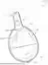
FIG. 1 is a perspective view of a vaporizer device, according to one implementation.
FIG. 2 is a front view of the vaporizer device of FIG. 1.
FIG. 3 is a side view of the vaporizer device of FIG. 1.
FIGS. 4 and 5 are perspective views of the vaporizer device of FIG. 1 in use.
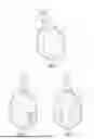
FIGS. 6A-6C are front views of several sizes of vaporizer devices, according to another implementation.
FIG. 6D is a front view of a cartridge for use in various implementations of vaporizer devices disclosed herein.
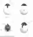
FIG. 7A is a side view of a pod style vaporizer device, according to another implementation.
FIG. 7B is a front view of the pod style vaporizer device of FIG. 7A.
FIG. 7C is a rear view of the pod style vaporizer device of FIG. 7A.
FIG. 8A is a front view of a vaporizer device, according to another implementation.
FIG. 8B is a side view of the vaporizer device of FIG. 8A.
FIG. 8C is a top view of the vaporizer device of FIG. 8A.
FIG. 8D is a perspective view of the vaporizer device of FIG. 8A.
DETAILED DESCRIPTION
The devices, systems, and methods disclosed herein provide for a vaporizer device having a body that is monostatic. Thus, the device is designed such that its one true resting position is on the bottom of the body of the device with the mouthpiece pointing upwardly relative to a gravitational axis.
Many vaporizer devices that use oils can become clogged if the devices are set on their side for an extended length of time. The oils are able to flow from the reservoir into the airflow path of the device without being vaporized, preventing air from flowing through the device.
Because the devices disclosed herein are monostatic and rest with their mouthpiece facing upwardly, gravity does not allow the oils to flow from the reservoir into the airflow path, which prevents the devices from becoming clogged.
The devices, systems, and methods disclosed herein further provide for a vaporizer device that includes a pressure sensor. The body of these devices can be squeezed by a user to activate the pressure sensor. The pressure sensor can be used for various controls. For example, in some implementations, a single squeeze/activation can cause the device to heat the contents of the vaporizer. In some implementations, the device requires multiple squeezes to cause the device to heat the contents of the vaporizer. This requires the user to perform some physical activity before using the vaporizer. In some implementations, the pressure sensor can sense the level of pressure provided and can cause the device to heat the contents of the vaporizer at a proportionate level.
The devices, systems, and methods disclosed herein further provide for a vaporizer device that includes a lung resistance device. The lung resistance device can be used similar to the pressure sensor in that it can measure the number of inhales/exhales of the user to activate the device. The lung resistance device can also restrict the flow of air through the device, increasing the pressure a user must produce to use the device.
The devices, systems, and methods disclosed herein further provide for a vaporizer device that includes a thermally conductive material extending from an outer surface of the device to the reservoir. A user can contact the thermally conductive material with their hand or finger to warm transfer body heat to the contents of the reservoir to preheat the contents.
Other benefits of a monostatic device include: (1) helping to prevent leaking from the bottom and the top of the cartridge due to less movement of the concentrate which can flow side to side and up and down; (2) helping to prevent clogging because less movement into the air holes at the bottom and mouthpiece at the top; (3) helping to prevent dirt and dust from sticking inside the mouthpiece where the oil can capture dust, dirt, or lint, which can introduce pathogens, bacteria, and even viruses to stick inside the mouthpiece residue; (4) helping to prevent the need for cleaning the opening(s) of the mouthpiece (e.g., with a toothpick or pin) or clearing the residue with one's lungs, which can damage the throat and allow hot oil to enter the user's mouth and throat; (5) helping to keep liquid oils/extracts/concentrates, which can take a while to even out once it has accumulated in one or more places, evenly distributed for more consistent heating; (6) helping to create a better flavor through consistent heating of the natural Terpenes of the oils/extracts/concentrates; (7) helping to prevent burning of the oils/extracts/concentrates on one side of the heating element due to uneven distribution of the oils/extracts/concentrates around the heating element, contaminating the unburned liquid; and (8) helping to prevent the device from rolling off a surface (e.g., a table or countertop) and breaking the cartridge filled with liquid oils/extracts/concentrates. It should be noted that, even if the devices disclosed herein were to fall to the ground, they would tend to land bottom first, protecting the glass cartridge from breaking on impact.
Various implementations include a vaporizer device. The device includes a weighted body and a vaporizing element. The weighted body has a first body end and a second body end opposite end spaced apart from the first body end. The second body end includes a curved surface. The vaporizing element is disposed within the weighted body. The device is couplable to a cartridge defining a reservoir such that a substance within the reservoir is vaporizable by heat from the vaporizing element. The device is monostatically shaped and weighted such that a stable equilibrium position of the device is located on the second body end.
FIG. 1 shows a vaporizer device 100 according to aspects of various implementations. The device 100 includes a cartridge 110, a weighted body 150, and a controller 150. The device 100 can further include a button, a sensor, an app, or any other method of causing the device to vaporize a substance within the device.
The cartridge 110 has a first cartridge end 112 and a second cartridge end 114 opposite and space apart from the first cartridge end 112. The cartridge 110 includes a reservoir 116 for containing a substance to be vaporized. The device 100 includes a vaporizing element 118 for vaporizing a substance disposed within the reservoir 116. Although the vaporizing element shown in FIGS. 1-5 includes a heating element for providing heat to the substance disposed within the reservoir 116, in some implementations, the vaporizing element can include any device capable of vaporizing a substance disposed within the reservoir, such as an ultrasonic vibration generator or a nebulizer.
The substance within the reservoir 116 can include any substance that includes at least one ingredient that can be extracted at a low enough temperature that the substance does not combust. For example, the substance can include an oil, a concentrate, or a plant or other botanical.
The cartridge 110 also includes a mouthpiece 120 coupled to the first cartridge end 112 of the cartridge 110. The mouthpiece 120 includes a central opening 122 through which vaporized substance from the reservoir 116 can pass. However, in some implementations, such as the device 800 shown in FIGS. 8A-8D, the mouthpiece 820 is a portion of the body 830. The mouthpiece 820 can be the first body end 832 and define a central opening 822 in the first body end 832 through which vaporized substance from the reservoir can pass. Instead of a user placing their mouth along a protruding mouthpiece, such as with other implementations disclosed herein, a user using the device 800 shown in FIGS. 8A-8D places there mouth directly on the first body end 832 to inhale the vaporized substance from the central opening 822.
As used herein, the term “cartridge” 110 can mean any device defining a reservoir capable of containing a substance that is in thermal communication with a vaporizing element of a vaporizing device. For example, a cartridge can include a pod.
The device 100 can include a button, sensor, or other means of activating the vaporizing element 118 to vaporize the substance within the reservoir 116, as discussed below.
The device 100 can include a thermally conductive material 140 extending from an outer surface of the device 100 to the reservoir 116 such that heat from the outer surface of the device 100 is transferable to the substance disposed within the reservoir 116. In some implementations, the thermally conductive material can include a metal such as copper, but in some implementations, the thermally conductive material can include any material capable of transferring heat from an outer surface of the device to the reservoir.
The body 130 of the device 100 includes a first body end 132 and a second body end 134 opposite and spaced apart from the first body end 132. The body 130 defines an inner cavity 136 disposed between the first body end 132 and the second body end 134. The first body end 132 includes a body opening 138 extending from an outer surface of the body 130 to the inner cavity 136.
The inner cavity 136 of the body 130 can be accessible such that the inner cavity 136 can be used as an ash tray or to store other items such as pre-rolled cigarettes. In some implementations, the body includes an external holder for such items.
The cartridge 110 is disposed within the body opening 138 such that the second cartridge end 114 is disposed within the inner cavity 136 of the body 130 and the first cartridge end 112 and the mouthpiece 120 extend away from the body 130. Thus, the cartridge 110 is coupled to the body 130 such that the second cartridge end 114 is closer than the first cartridge end 112 to the second body end 134 and the first cartridge end 112 is closer to the first body end 132 than it is to the second body end 134.
The cartridge 110 can be separate from the body 130 or can be integrally coupled to each other. In implementations in which the cartridge and body are separate, the cartridge and the body can include a coupling mechanism that allows the cartridge to be attached to the body such that the cartridge is in thermal communication with the vaporizing element. Such coupling mechanisms can include a standard 510 thread, a pod-style connector, or any other type of connection.
The second body end 134 includes a curved outer surface and the device 100 is weighted for the device to be monostatic. As used herein, the term “monostatic” is defined as any shape for which gravity causes the device to have a single reasonable stable equilibrium position. Thus, some monostatic designs may be of a shape that could allow balancing of the device in a second position that achieves equilibrium but are difficult or unreasonable to achieve. The curved surface of the second body end 134 has a center point 139 that is intersected by a longitudinal axis 119 of the cartridge 110 that extends between the first cartridge end 112 and the second cartridge end 114. The stable equilibrium position of the entire device 100 is located on the center point 139 of the second body end 134, which allows the longitudinal axis 119 of the cartridge 110 to be parallel to the gravitational axis when the device 100 is disposed in the stable equilibrium position.
At least a portion of the body 130 is made of a resilient material. The body 130 is biased toward the normal rounded convex shaped expanded position but is urgable toward a compresses position by applying pressure to the outer surface of the body 130. The amount of pressure required to urge the body 130 toward the compressed position can be predetermined by the manufacturer or can be selectively variable by the user (e.g., by adjusting supports, inner air pressure, restriction of flow of air in and out of body).
The controller 150 is disposed within the inner cavity 136 of the body 130 and includes a processor 152 and a system memory 154. The processor 152 is in operative communication with the vaporizing element 118 and one or more sensors. The processor 152 executes computer-readable instructions stored on the system memory 154 that cause the processor 152 to perform various actions.
The device 100 shown in FIG. XX includes a pressure switch 160 in operative communication with the processor 152. The pressure switch 160 shown in FIG. XX is a pressure sensor capable of sending variable signals based on a current pressure, but in some implementations, the pressure switch could be an on/off type switch. The pressure switch 160 is disposed within the inner cavity 136 and can be activated by the air within the inner cavity 136 of the body 130 when the body 130 is urged toward the compressed position. The sensor 160 produces a signal based on the pressure sensed, the processor 152 receives the signal as an input, and the processor 152 compares the input signal to a predetermined pressure threshold. If the signal exceeds the predetermined pressure threshold, the processor 152 causes an amount of amperage of an electrical current to be sent to the vaporizing element 118.
The predetermined pressure threshold can be a set amount of pressure, or it could be selectively adjustable by the user. This amperage could be enough to cause the vaporizing element 118 to begin vaporizing the substance disposed within the reservoir 116 or it could alter the rate of vaporization of the substance. For example, after receiving the input signal, the instructions can further cause the processor 152 to compare the input signal to a vaporizing signal profile stored on the system memory to determine a magnitude of a vaporizing signal. The amperage of the electrical current being sent to the vaporizing element 118 is then caused to be altered to be altered based on the vaporizing signal.
In some implementations, the instructions cause the processor to receive a set or selectable number of discrete signals that exceed the predetermined pressure threshold prior to causing an amount of amperage of an electrical current to be sent to the vaporizing element. This feature encourages the user to squeeze the body one or more times to promote grip strength.
The device 100 also includes a lung resistance device 162 disposed at the mouthpiece 120 of the cartridge 110. The lung resistance device 162 causes a resistance of gas passing through the central opening 122 of the mouthpiece 120, making it more difficult for a user to inhale and/or exhale through the mouthpiece 120. The lung resistance device 162 can be adjustable to selectively vary the resistance of gas passing through the mouthpiece 120, or it can be a set resistance. The lung resistance device 162 shown in FIG. XX causes resistance by selectively restricting a minimum cross-sectional area of the flow path of the vaporized substance from the reservoir 116 through the mouthpiece 120. However, in some implementations, the lung resistance device can cause resistance in any other way known in the art.
The lung resistance device 162 shown in FIG. XX is further in operative communication with the processor 152. The lung resistance device 162 includes a pressure or flow sensor that can be activated by air flowing through the mouthpiece 120. The sensor produces a signal based on the flowrate or pressure sensed, the processor 152 receives the signal as an input, and the processor 152 compares the input signal to a predetermined volume/flowrate/pressure threshold. If the signal exceeds the predetermined volume/flowrate/pressure threshold, the processor 152 causes an amount of amperage of an electrical current to be sent to the vaporizing element 118.
The predetermined volume/flowrate/pressure threshold can be a set volume, flowrate, or amount of pressure, or it could be selectively adjustable by the user. This amperage could be enough to cause the vaporizing element 118 to begin vaporizing the substance disposed within the reservoir 116 or it could alter the rate of vaporization of the substance. For example, after receiving the input signal, the instructions can further cause the processor 152 to compare the input signal to a vaporizing signal profile stored on the system memory 154 to determine a magnitude of a vaporizing signal. The amperage of the electrical current being sent to the vaporizing element 118 is then caused to be altered based on the vaporizing signal.
In some implementations, the instructions cause the processor to receive a set or selectable number of discrete signals that exceed the predetermined volume/flowrate/pressure threshold prior to causing an amount of amperage of an electrical current to be sent to the vaporizing element. This feature encourages the user to exert their lungs with one or more inhales and/or exhales to promote lung strength.
The device 100 further includes a solar cell 170. The solar cell 170 can provide energy to power the vaporizing element 118 and/or controller 150, e.g., directly or by charging a battery 124. The solar cell 170 can also be in operative communication with the processor 152 and act as a sensor for activating the vaporizing element 118.
The device 100 also includes a Bluetooth receiver 180 in operative communication with the processor 152. The instructions can cause the processor 152 to receive a signal from the Bluetooth receiver 180 from an external source to change one or more functions of the device 100. For example, in some implementations, the external source is a mobile device that includes an application having an interface that allows a user to interactively adjust threshold values or modes of the device.
It should be appreciated that any combination of the features described above are contemplated as being included in or excluded from some implementations of this device. For example, in some implementations, such as those shown in FIGS. 6A-6D, the device 600 includes the lung resistance device 662 and the thermally conductive material 640, but does not include the monostatic body or the pressure switch. FIGS. 6A-6C show various sizes of different implementations of the device, and FIG. 6D shows an example of a cartridge 610 that can be used in various implementations disclosed herein.
FIGS. 7A-7C show a pod style device 700 with some similar features to the devices 100, 600 shown in FIGS. 1-6D. However, the device 700 shown in FIGS. 6A-6C includes the pressure switch 760 that can be activated by depressing a side of the body 730 but does not include the lung resistance device or the thermally conductive material.
A number of example implementations are provided herein. However, it is understood that various modifications can be made without departing from the spirit and scope of the disclosure herein. As used in the specification, and in the appended claims, the singular forms “a,” “an,” “the” include plural referents unless the context clearly dictates otherwise. The term “comprising” and variations thereof as used herein is used synonymously with the term “including” and variations thereof and are open, non-limiting terms. Although the terms “comprising” and “including” have been used herein to describe various implementations, the terms “consisting essentially of” and “consisting of” can be used in place of “comprising” and “including” to provide for more specific implementations and are also disclosed.
Disclosed are materials, systems, devices, methods, compositions, and components that can be used for, can be used in conjunction with, can be used in preparation for, or are products of the disclosed methods, systems, and devices. These and other components are disclosed herein, and it is understood that when combinations, subsets, interactions, groups, etc. of these components are disclosed that while specific reference of each various individual and collective combinations and permutations of these components may not be explicitly disclosed, each is specifically contemplated and described herein. For example, if a device is disclosed and discussed each and every combination and permutation of the device are disclosed herein, and the modifications that are possible are specifically contemplated unless specifically indicated to the contrary. Likewise, any subset or combination of these is also specifically contemplated and disclosed. This concept applies to all aspects of this disclosure including, but not limited to, steps in methods using the disclosed systems or devices. Thus, if there are a variety of additional steps that can be performed, it is understood that each of these additional steps can be performed with any specific method steps or combination of method steps of the disclosed methods, and that each such combination or subset of combinations is specifically contemplated and should be considered disclosed.
Claims
1. A vaporizer device, the device comprising:
a weighted body having a first body end and a second body end opposite and spaced apart from the first body end, wherein the second body end includes a curved surface; and
a vaporizing element disposed within the weighted body, wherein the device is couplable to a cartridge defining a reservoir such that a substance within the reservoir is vaporizable by the vaporizing element,
wherein the device is monostatically shaped and weighted such that a stable equilibrium position of the device is located on the second body end.
2. The device of claim 1, wherein the cartridge has a first cartridge end and a second cartridge end opposite and spaced apart from the first cartridge end, wherein when the cartridge is coupled to the device, the second cartridge end is closer than the first cartridge end to the second body end and the first cartridge end is closer to the first body end than it is to the second body end, the cartridge further including a mouthpiece coupled to the first cartridge end, wherein the mouthpiece includes a central opening through which vaporized substance from the reservoir can pass.
3. The device of claim 1, wherein the cartridge is removably couplable to the device by a 510 thread or a pod-style connector.
4. (canceled)
5. (canceled)
6. The device of claim 1, wherein the curved surface of the second body end has a center point, wherein the stable equilibrium position of the device is the center point.
7. (canceled)
8. The device of claim 1, wherein the weighted body comprises a resilient material biased toward an expanded position and urgable toward a compressed position.
9. The device of claim 8, wherein the weighted body is convex shaped in the expanded position.
10. (canceled)
11. The device of claim 8, wherein the device further includes a pressure switch disposed within an inner cavity defined by the weighted body, wherein urging the weighted body toward the compressed position activates the pressure switch, wherein the activation of the pressure switch activates the vaporizing element to cause the substance within the reservoir to be vaporized.
12. (canceled)
13. The device of claim 11, wherein the pressure switch includes a pressure sensor, wherein the pressure switch is activated when a predetermined or selectable pressure is applied to the pressure switch.
14. (canceled)
15. The device of claim 2, further comprising the cartridge, wherein the device further includes a lung resistance device to selectively vary resistance of gas passing through the central opening of the mouthpiece.
16. The device of claim 15, wherein the lung resistance device selectively restricts a minimum cross-sectional area of the flow path of the vaporized substance from the reservoir through the mouthpiece.
17. The device of claim 15, wherein the flow of gas through the cartridge causes the activation of the vaporizing element.
18. The device of claim 17, wherein the vaporizing element is activated after a predetermined or selectable amount of gas flow through the cartridge is detected.
19. (canceled)
20. The device of claim 17, wherein the vaporizing element is activated after a predetermined or selectable number of inhales, exhales, or both of gas through the cartridge is detected.
21. (canceled)
22. The device of claim 1, wherein the device includes a thermally conductive material extending from an outer surface of the device to the reservoir when the device is coupled to the cartridge such that heat from the outer surface of the device is transferable to the substance disposed within the reservoir.
23. The device of claim 22, wherein the thermally conductive material comprises metal.
24. (canceled)
25. The device of claim 1, further comprising a processor and a system memory, the processor being in operative communication with the vaporizing element, wherein the processor executes computer-readable instructions stored on the system memory, the instructions causing the processor to:
receive an input, and
cause an amperage of an electrical current being sent to the vaporizing element to be altered based on the input.
26. The device of claim 25, wherein the input is provided to the device by an external device.
27. The device of claim 25, wherein the input is provided by a sensor.
28. The device of claim 25, wherein the instructions further cause the processor to:
after receiving the input, compare the input to a vaporizing signal profile stored on the system memory to determine a vaporizing element, and
wherein the amperage of the electrical current being sent to the vaporizing element is caused to be altered to be altered based on the vaporizing signal.
29. (canceled)
30. The device of claim 1, wherein the vaporizing element comprises a heating element.
31.-148. (canceled)
Images & Drawings included:


Sources:
- United States Patent and Trademark Office - verify current appl. status at the USPTO↗
Similar patent applications:
- » 20200288780
SMOKING VAPORIZER WITH BUILT IN SMOKE FILTRATION SYSTEM - » 20240325345
Methods of increasing effects of the ingestion of drugs such as cannabis or 5ht2 agonists via applications with 5ht1/2, CB1, opiate allosteric modulators as/in foods, beverages, vaporizer, smoking and supplement products/formulations. - » 20180345164
BUBBLE GUN WITH SIMULATED VAPOR SMOKE - » 20190261679
BOWL ASSEMBLY FOR A VAPOR SMOKING DEVICE - » 20240315323
Reduction of amines and nitrosamines in cigarette smoke vapors through a filter functionalized with olive tree polyphenols - » 20240325344
Methods of reducing symptoms of the ingestion of drugs such as cannabis or 5ht2 agonists via applications with 5ht1/2, CB1, GLP-1 allosteric modulators as/in foods, beverages, vaporizer, smoking and supplement products/formulations. - » 20250049110
Smoke Vapor Tar Condenser Comprising A Tar Condensing Chamber and Condensing Medium In A Disposable Bowl Liner for Easy Insertion and Removal from A Pipe-Like Structure - » 20160151718
Model locomotive with vapor-smoking and furnace-firing-and-lighting effects - » 20240315315
COMPOSITION AND METHOD FOR SUPPRESSING PERCEPTION OF SMOKE OR VAPOR ODOR AND FOR SMOKING OR VAPING CESSATION - » 20120048286
Smoking articles with significantly reduced gas vapor phase smoking constituents
Recent applications in this class:
- » 20250169535 2025-05-29
AEROSOL DELIVERY DEVICE WITH VISIBLE INDICATOR - » 20250169534 2025-05-29
CARTRIDGE FOR USE WITH APPRATUS FOR HEATING SMOKABLE MATERIAL - » 20250160409 2025-05-22
ATOMIZER AND ELECTRONIC ATOMIZATION APPARATUS - » 20250160408 2025-05-22
APPARATUS FOR HEATING AREOSOL GENERATING MATERIAL - » 20250160407 2025-05-22
AEROSOL DELIVERY DEVICE WITH DOWNSTREAM FLAVOR CARTRIDGE - » 20250160406 2025-05-22
ELECTRONIC CIGARETTE AND NOZZLE ASSEMBLY - » 20250160405 2025-05-22
CONNECTORS FOR FORMING ELECTRICAL AND MECHANICAL CONNECTIONS BETWEEN INTERCHANGEABLE UNITS IN AN AEROSOL DELIVERY SYSTEM - » 20250160404 2025-05-22
ATOMIZERING DEVICE - » 20250151789 2025-05-15
Vaporizer Cartridge With Snap Spring - » 20250143371 2025-05-08
ATOMIZER AND ELECTRONIC ATOMIZATION DEVICE