Device and method for creating bubbles
US20250114722A1
2025-04-10
18/774,750
2024-07-16
Smart Summary: A bubble device uses a tube filled with bubble solution to create bubbles. Users can blow air through the tube to make the bubbles form. The design helps produce a lot of bubbles easily and quickly. It is fun for both kids and adults to play with. This device makes bubble-making simple and enjoyable. 🚀 TL;DR
Abstract:
The present disclosure discloses a bubble device having a tube containing bubble solution.
Applicant:
Interested in similar patents?
Get notified when new applications in this technology area are published.
Description
RELATED APPLICATION
The present application claims the benefit of U.S. Provisional Application No. 63/513,889, filed Jul. 16, 2023, naming Daniele DeGraff, and titled “DEVICE AND METHOD FOR CREATING BUBBLES,” the entire disclosure of which is expressly incorporated by reference herein.
FIELD OF THE INVENTION
The present disclosure is directed to devices and methods for creating bubbles.
BACKGROUND AND SUMMARY OF THE DISCLOSURE
The following statements are intended to facilitate an understanding of the present disclosure. The statements are to be read in this light and should not be construed as admissions of prior art.
Some find enjoyment from creating bubbles from a liquid, such as bubble solution. On occasion, children and others may create bubbles for entertainment. On other occasions, some may create bubbles at an event, such as greeting newly married couples after a wedding or other events.
According to the present disclosure a bubble device is provided that includes a tube, such as a straw, that creates bubbles. For example, according to one example, a bubble device is provided that includes a tube, bubble solution positioned within the tube, at least one bubble solution aperture, and at least one film aperture positioned to receive bubble solution from the at least one bubble solution aperture to create a film over the at least one film aperture and create bubbles when a user blows on the tube.
Additional features of the present disclosure will become apparent to those skilled in the art upon consideration of the following detailed description of the illustrative embodiment exemplifying the best mode of carrying out the disclosure as presently perceived.
BRIEF DESCRIPTION OF THE DRAWINGS
The detailed description of the drawings particularly refers to the accompanying figures in which:
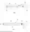
FIG. 1 is side view of a person blowing on a first end of a bubble device to create bubbles;
FIG. 2 is a view similar to FIG. 1 of the bubble device of FIG. 1 showing the user removing a seal cap from a tube of the bubble device to permit bubble solution to flow through solution apertures located at a second end of the bubble device;
FIG. 3 is a perspective view of a ring of the bubble device of FIG. 1 positioned on the second end of the tube showing the ring defining the solution apertures and a film aperture over which the bubble solution flows prior to the creation of the bubbles;
FIG. 4 is side view of a person blowing on a first end of an alternative embodiment bubble device to create bubbles;
FIG. 5 is a side view of side view a ring of the bubble device of FIG. 4 positioned on a second end of the tube showing the ring defining a plurality of fingers having solution apertures;
FIG. 6 is side view of a person blowing on a first end of another alternative embodiment bubble device to create bubbles;
FIG. 7 is a view similar to FIG. 6 of the bubble device of FIG. 6 showing a user removing a seal cap from a tube of the bubble device to permit bubble solution to flow through solution apertures located at a second end of the bubble device;
FIG. 8 is an end view of the second end of the bubble device of FIG. 6 (with an end cap removed for clarity) showing the solution apertures (shown in phantom), the seal cap positioned over the solution apertures, and a plurality of film apertures positioned below the seal cap;
FIG. 9 is an end view of the end cap showing the plurality of film apertures and a portion of the seal cap extending through a crescent-shaped aperture of the end cap;
FIG. 10 is side view of a person blowing on a first end of another alternative embodiment bubble device to create bubbles;
FIG. 11 is an end view of a second view of the bubble device of FIG. 10 (with an end cap removed) showing a second end of a tube including a plurality of circular solution apertures and a pair of pie piece-shaped apertures;
FIG. 12 is an end view of the end cap of the bubble device of FIG. 10 showing the end cap including four pie piece-shaped film apertures;
FIG. 13 is a cross-sectional view of the tube of the bubble device of FIG. 10 showing the tube include a pair of bubble solution chambers and a pair of air chambers;
FIG. 14 is a side view of the second end of the tube and the cap prior to coupling of the cap to the tube showing a plurality of prongs;
FIG. 15 is a view similar to FIG. 14 showing the prongs partially positioned in the tube; and
FIG. 16 is a view similar to FIG. 15 showing the prongs rotated inward 180 degrees from the position shown in FIG. 14.
For the purpose of promoting an understanding of the principals of the disclosure, reference will now be made to the embodiments illustrated in the drawings, which are described below. The embodiments disclosed below are not intended to be exhaustive or limit the disclosure to the precise form disclosed in the following detailed description. Rather, the embodiments are chosen and described so that others skilled in the art may utilize their teachings. It will be understood that no limitation of the scope of the disclosure is thereby intended. The disclosure includes any alterations and further modifications in the illustrative devices and further applications of the principles of the disclosure which would normally occur to one skilled in the art to which the disclosure relates. Unless otherwise indicated, the components in the drawings are shown proportional to each other.
DETAILED DESCRIPTION OF THE DRAWINGS
As depicted in FIG. 1, a bubble device or straw 10 is shown that allows a user to create bubbles 12. Bubble device 10 includes a tube 14, a first seal cap 16, a second seal cap 18 sealing over a solution ring 20. Tube 14 includes a liquid bubble solution chamber 22 surrounding an cylindrical chamber 24 positioned inside of solution chamber 22. When second seal cap 18 is removed, a user 26 blows into tube 14, creating bubbles 12 from bubble solution 6 in bubble solution chamber 22 that flows over a solution ring 20. Solution ring 20 includes a plurality of solution apertures 28 including outer solutions apertures 28′ and inner solution apertures 28″ and a film aperture 30. When second seal cap 18 is removed and user 26 squeezes tube 14, bubble solution 6 flows from solution apertures 28 over film aperture 30, creating a film over film aperture 30. Air blown by user 26 creates bubbles 12.
As depicted in FIG. 4, another bubble device or straw 110 is shown that allows a user to create bubbles 12. Bubble device 110 includes a tube 114, a seal cap 118 sealing over a solution ring 120. Bubble device 110 includes a liquid bubble solution chamber 122 and tube 114 includes an air chamber 124. When second seal cap 118 is removed, user 26 blows into tube 114, creating bubbles 12 from bubble solution 6 that flows over a solution ring 120. Solution chamber 122 includes a bladder 121 and tube 123. Solution ring 120 includes a plurality of fingers 126 including solution apertures 128 and in inner passage 127 communicating bubble solution 6 to solution apertures 128. When second seal cap 118 is removed as shown in FIG. 7 and user 26 squeezes tube 114 and bladder 121, bubble solution 6 flows from solution apertures 128 over film aperture 130, creating a film over film aperture 130. Air blown by user 26 creates bubbles 12.
As depicted in FIG. 6, another bubble device or straw 210 is shown that allows a user to create bubbles 12. Bubble device 210 includes a tube 214, a seal cap 218 sealing over a solution ring 220. Tube 214 includes a liquid bubble solution chamber 222 and an air chamber 224. When seal cap 218 is removed, user 26 blows into tube 214, creating bubbles 12 from bubble solution 6 that flows over a solution ring 220. Solution ring 120 includes a plurality of solution apertures 228 as shown in FIG. 8. When seal cap 218 is removed and user 26 squeezes tube 214, bubble solution flows from solution apertures 228 over four tear-shaped film apertures 230, creating a film over film aperture 230. Ribs. 232 direct bubble solution 6 over film apertures 230. A portion of seal cap 218 is positioned between an end cap 234 and solution ring 220. Solution apertures 228 are positioned behind end cap 234 and above a crescent-shaped aperture 236 in end cap 234 as shown in FIG. 9. When tube 214 is squeezed by user 26, bubble solution 6 impacts an inner side of end cap 234 and flows down over film apertures 230. Air blown by user 26 creates bubbles 12 at film apertures 230 that passes through crescent-shaped aperture 236.
As depicted in FIG. 10, another bubble device or straw 310 is shown that allows a user to create bubbles 12. Bubble device 310 includes a tube 314, a seal cap 318 sealing over a solution ring 320. Tube 314 includes a pair of pie piece-shaped liquid bubble solution chambers 322 and a pair of pie piece-shaped air chambers 324. When seal cap 318 is rotated, user 26 blows into tube 314, creating bubbles 12 from bubble solution 6 that flows over a solution ring 320. Solution ring 320 includes four solution apertures 328 initially covered by an adhesive (not shown). When seal cap 318 is rotated, the adhesive is removed from covering solution apertures 328 and user 26 squeezes tube 314, bubble solution 6 flows from solution apertures 328 over film apertures 330 in seal cap 318, creating a film over film apertures 330. Air blown by user 26 creates bubbles 12. While continuing to blow, user 26 continues to rotate seal cap 318, distributing bubble solution over film apertures 330 to create additional film over film apertures 330 and create more bubbles 12.
As depicted in FIG. 14, seal cap 318 includes a plurality of prongs 332. Prior to assembly of seal cap 318 on tube 314, prongs 332 extend outward. During assembly, end portions of prongs 332 are initially placed inside tube 314. As seal cap 318 is pressed further onto tube 314, prongs 332 rotate inward 180 degrees over an annular rim 334 of tube 314 until prongs 332 are pushed past annular rim 334, securing seal cap 318 on tube 314.
All components of bubble devices 10, 110, 210, 310 may be composed of natural plant fiber, PLA (Polylactic acid), composite PLA, wood, marble-colored PLA (such as eMarble brand marble colored PLA) and/or PLA with glitter (such as eTwinkling brand PLA with glitter) or other biodegradable or non-biodegradable materials.
Claims
I claim:1. A bubble device including
a tube,
bubble solution positioned within the tube,
at least one bubble solution aperture, and
at least one film aperture positioned to receive bubble solution from the at least one bubble solution aperture to create a film over the at least one film aperture and create bubbles when a user blows on the tube.
Images & Drawings included:


Sources:
- United States Patent and Trademark Office - verify current appl. status at the USPTO↗
Similar patent applications:
- » 20080213002
Bubble creating method, bubble creating device, bubbly fixation fluid producing method, bubbly fixation fluid producing device, fixation fluid, image forming method, and image forming apparatus - » 20160287809
Medical devices and methods for creating bubbles - » 20170333640
MEDICAL DEVICES AND METHODS FOR CREATING BUBBLES
Recent applications in this class:
- » 20250153069 2025-05-15
CUSTOMIZABLE BUBBLE CANNON - » 20250114721 2025-04-10
TRANSMISSION STRUCTURE FOR MINI BUBBLE MACHINE - » 20250025803 2025-01-23
BUBBLE BLOWING DEVICE WITH REPLACEABLE BUBBLE BLOWING TURNTABLE - » 20250001324 2025-01-02
BUBBLE PRODUCING DEVICE - » 20240375023 2024-11-14
Bubble machine - » 20240367071 2024-11-07
Automatic Bubble Machine - » 20240066424 2024-02-29
CHOMPING BUBBLE PRODUCING TOY - » 20230285871 2023-09-14
Apparatus for generating bubbles - » 20230277954 2023-09-07
ANIMATED BUBBLE TOY CUSTOMIZABLE AND ACTIVATED BY THE ATTACHMENT OF AN ACCESSORY - » 20230277953 2023-09-07
TOY FOR PRODUCING BUBBLES, SMOKE, AND SMOKE-FILLED BUBBLES